11.Removeanddiscardthecapfromthefuse(10A,58
V)asshowninFigure9.
Note:Thefusehasaredwireandayellowwire
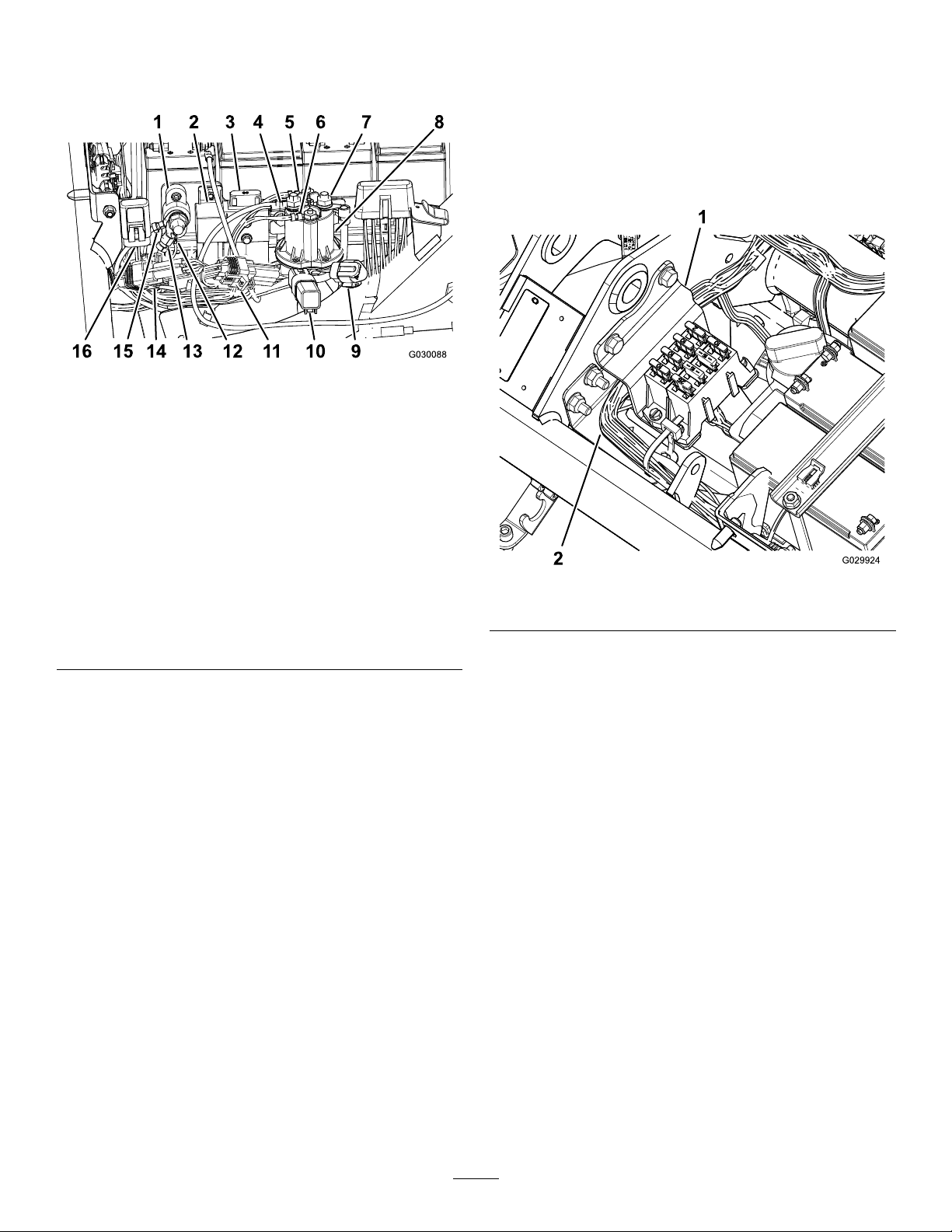
Figure9
1.Groundblock9.E-reels-CANdiagnostic
port
2.E-reelsenablerelay10.Protectiondiode
3.E-reelsfuse(60A,58V),
existing
11.IDmodule
4.Battery-sidepower(boot
notshown)
12.Harnessground
5.Main-contactor-coil
connector(white)
13.Harnessground
6.Main-contactor-coil
connector(brown)
14.CAN-interfacemodule
7.Switched-sidepower(boot
notshown)
15.E-reelsbatteriesground
8.Contactor(48VDC)16.Fuse(10A,58V)
12.Inserttheterminalwiththefuse(10A,58V)intothe
existingcapmountedontheframeofthemachine
(Figure9).
13.ConnecttheE-Reelsenablerelayconnector(P07)as
showninFigure9.
14.Connectthe90-degreeswitchedside(J07)connector
onthewireharnesstotherearterminalonthe
contactor(48VDC),andsecureittotheterminal
(Figure9).
15.Routethewireundertheangeonthecontactor(48
VCD).
16.Connectthe2main-contactor-coilconnectorstothe
contactor(48VDC)asshowninFigure9.
17.Connectthewiremarked“BatterySide”andthe
battery-disconnectwiretothefrontterminalofthe
contactor(48VDC)asshowninFigure9.
18.Slidetheinsulatorbootsfortheswitched-sidepower
connectorandthebattery-sideconnectoroverthe
terminalstocoverthem.
19.ConnecttheIDmodule(P08)asshowninFigure9.
20.ConnecttheCAN-interfacemodule(P10)asshown
inFigure9.
21.Connectthereel-speedswitch(P04)undertheseat.
22.Connectthe2terminals(CAN-businterconnectand
interfacetomainwireharness)onthenewwireharness
withthe2terminalsonthemainwireharnessunder
theseat.
23.Installthefuseblock(Figure10).
Note:Routethewireharnessbehindthebracket.
Figure10
1.Bracket2.Wireharness
24.Connecttheground-terminalconnectors(J06andJ08)
tothegroundblock(Figure9).
25.Usecabletiestosecurethewirestothemainwire
harnessandtothemachineframe.
Important:Ensurethatthewiresareawayfrom
movingparts.
26.Securethewireharnesstothemachineframebehind
andinfrontofthefuel-tankbracket.
27.Usecabletiestosecurethenewwireharness.
Important:Ensurethattheseatassemblydoes
notcrushthewires.
4