Toro GreensPro 1200 User manual

Service Manual
GreensPro™ 1200
PART NO. 12193SL
© The Toro Company - 2013
Preface
The purpose of this publication is to provide the service
technician with information for troubleshooting, testing,
and repairing assemblies and components on the
GreensPro 1200.
REFER TO THE OPERATOR’S MANUAL FOR
OPERATING, MAINTENANCE, AND ADJUSTMENT
INSTRUCTIONS. Space is provided in Chapter 2 of
this book to insert the Operator’s Manual and Parts
Catalog for your machine. Replacement catalogs are
available on the Internet at www.toro.com.
The Toro Company reserves the right to change
product specifications or this publication without notice.
NOTE: A NOTE will give general information about the
correct operation, maintenance, service, testing, or
repair of the machine.
IMPORTANT: The IMPORTANT notice will give
important instructions which must be followed to
prevent damage to systems or components on the
machine.
This safety symbol means DANGER,
WARNING, or CAUTION, PERSONAL SAFETY
INSTRUCTION. When you see this symbol,
carefully read the instructions that follow.
Failure to obey the instructions may result in
personal injury.

Greens Pro 1200
This page is intentionally blank.

Greens Pro 1200
Chassis Hydraulic
System
Gasoline
Engine
Product Records
and Maintenance
Safety
Table Of Contents
Chapter 1 - Safety
Safety Instructions ................................................... 1-2
Safety and Instruction Decals .................................. 1-4
Chapter 2 - Product Records and Maintenance
Product Records ...................................................... 2-2
Maintenance ............................................................ 2-2
Equivalents and Conversions .................................. 2-3
Torque Specifications .............................................. 2-4
Chapter 3 - Gasoline Engine
Introduction .............................................................. 3-2
Specifications........................................................... 3-3
General Information ................................................. 3-4
Service and Repairs ................................................ 3-5
Chapter 4 - Hydraulic System
Introduction .............................................................. 4-2
Specifications........................................................... 4-3
General Information ................................................. 4-5
Service and Repairs ................................................ 4-8
HYDRO-GEAR BDR SERVICE AND
REPAIR MANUAL
Chapter 5 - Chassis
Specifications........................................................... 5-2
General Information ................................................. 5-3
Adjustments ............................................................. 5-6
Service and Repairs .............................................. 5-11

Greens Pro 1200
This page is intentionally blank.

GreensPro 1200 Page 1 - 1 Safety
Chapter 1
Safety
Safety
Safe ty
Table of Contents
Safety Instructions ........................................ 1-2
Before Operating ................................................ 1-2
While Operating.................................................. 1-2
Maintenance and Service ................................... 1-3
Safety and Instruction Decals ...................... 1-4

Safety Page 1 - 2 GreensPro 1200
Safety Instructions
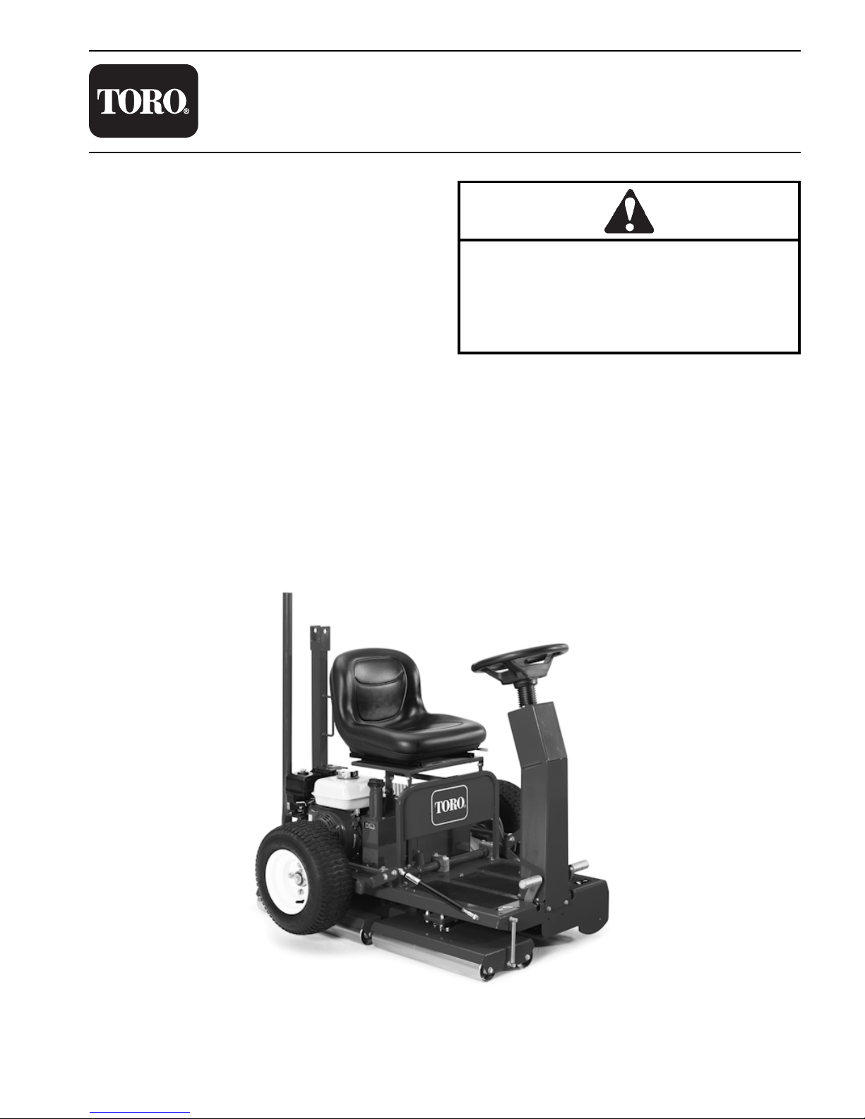
GreensPro 1200 machines have been tested and
certified by Toro for compliance with existing safety
standards and specifications. Although hazard control
and accident prevention are partially dependent upon
the design and configuration of the machine, these
factors are also dependent upon the awareness,
concern, and proper training of the personnel involved
in the operation, transport, maintenance, and storage
of the machine. Improper use or maintenance of the
machine can result in injury or death. To reduce the
potential for injury or death, comply with the following
safety instructions.
WARNING
Before Operating
1. Operate the machine only after reviewing and
understanding the contents of the Operator’s Manual. A
replacement Operator’s Manual is available on the
internet at www.toro.com.
2. Never allow children to operate the machine or allow
adults to operate it without proper instructions.
3. Become familiar with the controls and know how to
stop the machine and engine quickly.
4. Keep all shields, safety devices, and decals in place.
If a shield, safety device, or decal is malfunctioning,
illegible, or damaged, repair or replace it before
operating the machine.
5. Always wear substantial shoes. Do not operate
machine while wearing sandals, tennis shoes, or
sneakers. Do not wear loose fitting clothing, which
could get caught in moving parts and cause personal
injury.
6. Wearing safety glasses, safety shoes, long pants,
ear protection, and a hard hat is advisable and required
by some local safety and insurance regulations.
7. Keep everyone, especially children and pets, away
from the areas of operation.
8. Since gasoline is highly flammable, handle it
carefully.
a. Use an approved gasoline container.
b. Do not remove cap from fuel tank when engine is
hot or running.
c. Do not smoke while handling gasoline.
d. Fill fuel tank outdoors.
e. Wipe up any spilled gasoline.
f. Do not fill fuel tank higher than to the bottom of
fuel tank insert. Fuel may leak from filler neck when
machine is tilted for servicing if tank is overfilled.
While Operating
1. Do not run the engine in a confined area without
adequate ventilation. Exhaust fumes are hazardous
and could be deadly.
2. Always stand behind the machine when starting the
engine. Always sit in the operator’s seat when
operating the machine.
3. To start the engine:
a. Open fuel shutoff valve. Make sure spark plug
wire is connected to spark plug.
b. Move on/off switch to ON position. Set choke to
full choke position (cold start) and throttle to half
throttle.
c. Pull starter cord to start engine.
4. To stop the engine:
a. Reduce engine speed to SLOW.
b. Move on/off switch to OFF position to stop
engine.
5. Do not touch engine, muffler, or exhaust pipe while
engine is running or soon after it has stopped, because
these areas are hot enough to cause burns.
6. Whenever machine is left unattended, park machine
on a level surface and be sure engine is stopped.
7. Close fuel shutoff valve if machine is not to be used
for an extended period of time. Also, close fuel shutoff
valve if machine is to be transported.
To reduce the potential for injury or death,
comply with the following safety instructions.

GreensPro 1200 Page 1 - 3 Safety
Safety
Maintenance and Service
1. The Operator’s Manual and engine Owner’s Manual
provide information regarding the operation, general
maintenance, and maintenance intervals for your
GreensPro machine. Refer to these publications for
additional information when servicing the machine.
2. Before servicing or making adjustments to the
machine, stop the engine and wait for all machine
motion to stop. Remove the spark plug wire from the
spark plug to prevent accidental starting of the engine.
If Greenspro is attached to tow vehicle, apply tow
vehicle parking brake, stop engine, and remove key
from ignition switch.
3. To make sure entire machine is in good condition,
keep all nuts, bolts, screws, and belts properly
tightened.
4. To reduce potential fire hazard, keep the engine
area free of excessive grease, grass, leaves, and
accumulation of dirt.
5. If the engine must be running to perform
maintenance or make an adjustment, keep hands, feet,
clothing, and all parts of the body away from all moving
parts. Keep bystanders away.
6. Do not overspeed the engine by changing governor
settings. Recommended engine high idle speed is
3200 rpm. To ensure safety and accuracy, check
engine speed with a tachometer.
7. Engine must be shut off and cooled down before
checking oil or adding oil to the engine crankcase.
8. When performing general maintenance and service
on the machine, it is recommended that the machine
be parked on a clean, level surface with the transport
wheels in the raised and locked position. The machine
will be more stable when positioned on the rollers.
9. If service of underdeck items (e.g., steering or
transmission linkage) is necessary, raise machine with
hoist or other lifting device. Support raised machine
with appropriate jackstands on all corners of the
machine to prevent it from shifting or falling. Excessive
tilting of the machine should be avoided.
10.When lowering machine from transport position,
make sure that the ground is clean and level. This will
prevent unexpected movement of the machine and
potential roller damage.
11.If major repairs are necessary or assistance is
required, contact your Authorized TORO Distributor.
12.At the time of manufacture, the machine conformed
to all applicable safety standards. To ensure optimum
performance and continued safety certification of the
machine, use genuine TORO replacement parts and
accessories. Replacement parts and accessories
made by other manufacturers may result in non-
conformance with the safety standards and the
warranty may be voided.
13.When disposing of hazardous waste products, take
them to an authorized disposal site. Waste products
must not be allowed to contaminate surface water,
drains, or sewer systems.

Safety Page 1 - 4 GreensPro 1200
Safety and Instruction Decals
Safety decals and instructions are easily visible to the
operator and are located near any area of potential
danger. Replace any decal that is damaged or lost.
Decal part numbers are listed in your Parts Catalog.
Order replacement decals from your Authorized TORO
Distributor.

GreensPro 1200 Page 2 - 1 Product Records and Maintenance
Chapter 2
Product Records and Maintenance
Product Records
and Maintenance
Product Reco rds and Maintenan ce
Table of Contents
Product Records............................................ 2-2
Maintenance ................................................... 2-2
Equivalents and Conversions ...................... 2-3
Decimal and Millimeter Equivalents.................... 2-3
U.S. to Metric Conversions................................. 2-3
Torque Specifications ................................... 2-4
Fastener Identification ........................................ 2-4
Standard Torque for Dry, Zinc Plated, and
Steel Fasteners (Inch Series Fasteners) ............ 2-5
Standard Torque for Dry, Zinc Plated, and
Steel Fasteners (Metric Fasteners) .................... 2-6
Other Torque Specifications ............................... 2-7
Conversion Factors ............................................ 2-7

Product Records and Maintenance Page 2 - 2 GreensPro 1200
Product Records
Insert Operator’s Manual and Parts Catalog for your
GreensPro 1200 at the end of this section. In addition,
if any optional equipment or accessories have been
installed to your machine, insert the Installation
Instructions, Operator’s Manuals, and Parts Catalogs
for those options at the end of this chapter.
Maintenance
Maintenance procedures and recommended service
intervals for the GreensPro 1200 are covered in the
Operator’s Manual. Refer to that publication when
performing regular equipment maintenance.

GreensPro 1200 Page 2 - 3 Product Records and Maintenance
Product Records
and Maintenance
Equivalents and Conversions
Decimal and Millimeter Equivalents
U.S. to Metric Conversions
0.765625
0.78125
0.796875
0.8125
0.828125
0.84375
0.859375
0.8750
1.000
0.984375
0.96875
0.953125
0.9375
0.921875
0.90625
0.890625
0.640625
0.65625
0.671875
0.6875
0.703125
0.71875
0.734375
0.7500
0.6250
0.609375
0.59375
0.578125
0.5625
0.546875
0.53125
0.515625
1/64
Fractions
0.015625
0.03125
0.046875
0.0625
0.078125
0.09275
0.109375
0.1250
0.2500
0.234375
0.21875
0.203125
0.1875
0.171875
0.15625
0.140625
0.390625
0.40625
0.421875
0.4375
0.453125
0.46875
0.484375
0.5000
0.3750
0.359375
0.34375
0.328125
0.3125
0.296875
0.28125
0.265625
Decimals mm
19.447
19.844
20.241
20.638
21.034
21.431
21.828
22.225
25.400
25.003
24.606
24.209
23.812
23.416
23.019
22.622
16.272
16.669
17.066
17.463
17.859
18.256
18.653
19.050
15.875
15.478
15.081
14.684
14.288
13.891
13.494
13.0970.397
0.794
1.191
1.588
1.984
2.381
2.778
3.175
6.350
5.953
5.556
5.159
4.762
4.366
3.969
3.572
9.922
10.319
10.716
11.112
11.509
11.906
12.303
12.700
9.525
9.128
8.731
8.334
7.938
7.541
7.144
6.747
Fractions Decimals mm
1/32
3/64
1/16
5/64
3/32
7/64
9/64
5/32
11/64
3/16
13/64
7/32
15/64
1/4
1/8
17/16
9/32
19/64
5/16
21/64
11/32
23/64
3/8
25/64
13/32
27/64
7/64
29/64
15/32
31/64
1/2
33/64
17/32
35/64
9/16
37/64
19/32
39/64
5/8
41/64
21/32
43/64
11/16
45/64
23/32
47/64
3/4
49/64
25/32
51/64
13/16
53/64
27/32
55/64
7/8
57/64
29/32
59/64
15/16
61/64
31/32
63/64
1
1 mm = 0.03937 in. 0.001 in. = 0. 0254 mm
To Convert Into Multiply By
Linear
Measurements
Miles
Yards
Feet
Feet
Inches
Inches
Inches
Kilometers
Meters
Meters
Centimeters
Meters
Centimeters
Millimeters
1.609
0.9144
0.3048
30.48
0.0254
2.54
25.4
Area Square Miles
Square Feet
Square Inches
Acre
Square Kilometers
Square Meters
Square Centimeters
Hectare
2.59
0.0929
6.452
0.4047
Volume Cubic Yards
Cubic Feet
Cubic Inches
Cubic Meters
Cubic Meters
Cubic Centimeters
0.7646
0.02832
16.39
Weight Tons (Short)
Pounds
Ounces (Avdp.)
Metric Tons
Kilograms
Grams
0.9078
0.4536
28.3495
Pressure Pounds/Sq. In.
Pounds/Sq. In.
Kilopascal
Bar
6.895
0.069
Work Foot-pounds
Foot-pounds
Inch-pounds
Newton-Meters
Kilogram-Meters
Kilograms-Centimeter
1.356
0.1383
1.152144
Liquid Volume Quarts
Gallons
Liters
Liters
0.9463
3.785
Liquid Flow Gallon/Minutes Liters/Minute 3.785
Temperature Fahrenheit Celsius 1. Subtract 32
2. Multiply by 5/9
˚

Product Records and Maintenance Page 2 - 4 GreensPro 1200
Torque Specifications
Recommended fastener torque values are listed in the
following tables. For critical applications, as determined
by Toro, either the recommended torque or a torque
that is unique to the application is clearly identified and
specified in this Service Manual.
These Torque Specifications for the installation and
tightening of fasteners shall apply to all fasteners that
do not have a specific requirement identified in this
Service Manual. The following factors shall be
considered when applying torque: cleanliness of the
fastener, use of a thread sealant (e.g., Loctite
®
),
degree of lubrication on the fastener, presence of a
prevailing torque feature (e.g., Nylock nut), hardness of
the surface underneath the fastener’s head, or a similar
condition that affects the installation.
As noted in the following tables, torque values should
be reduced by 25% for lubricated fasteners to achieve
the similar stress as a dry fastener. Torque values may
also have to be reduced when the fastener is threaded
into aluminum or brass. The specific torque value
should be determined based on the aluminum or brass
material strength, fastener size, length of thread
engagement, etc.
The standard method of verifying torque shall be
performed by marking a line on the fastener (head or
nut) and mating part, then backing off fastener 1/4 of a
turn. Measure the torque required to tighten the
fastener until the lines match up.
Fastener Identification
(Figures 1 and 2.)
Figure 1: Inch Series Bolts and Screws
Figure 2: Metric Bolts and Screws
Grade 5 Grade 8Grade 1
Class 8.8 Class 10.9

GreensPro 1200 Page 2 - 5 Product Records and Maintenance
Product Records
and Maintenance
Standard Torque for Dry, Zinc Plated, and Steel Fasteners (Inch Series Fasteners)
NOTE: Torque values may have to be reduced when
installing fasteners into threaded aluminum or brass.
The specific torque value should be determined based
on the fastener size, the aluminum or base material
strength, length of thread engagement, etc.
NOTE: Reduce torque values listed in the table above
by 25% for lubricated fasteners. Lubricated fasteners
are defined as threads coated with a lubricant such as
engine oil or thread sealant such as Loctite
®
.
NOTE: The nominal torque values listed above for
Grade 5 and 8 fasteners are based on 75% of the
minimum proof load specified in SAE J429. The
tolerance is approximately ± 10% of the nominal torque
value. Thin height nuts include jam nuts.
Thread Size
Grade 1, 5, &
8withThin
Height Nuts
SAE Grade 1 Bolts, Screws, Studs, &
Sems with Regular Height Nuts
(SAE J995 Grade 2 or Stronger Nuts)
SAE Grade 5 Bolts, Screws, Studs, &
Sems with Regular Height Nuts
(SAE J995 Grade 2 or Stronger Nuts)
SAE Grade 8 Bolts, Screws, Studs, &
Sems with Regular Height Nuts
(SAE J995 Grade 5 or Stronger Nuts)
in--lb in--lb N·m in--lb N·m in--lb N·m
# 6 -- 32 UNC
1
0
+
2
1
3
+
2
15 + 2 23 + 3
# 6 -- 40 UNF
10 + 2 13 + 2
17 + 2 25 + 3
# 8 -- 32 UNC
1
3
+
2
2
5
+
5
29 + 3 41 + 5
# 8 -- 36 UNF
13 + 2 25 + 5
31 + 4 43 + 5
#10--24UNC
1
8
+
2
3
0
+
5
42 + 5 60 + 6
#10--32UNF
18 + 2 30 + 5
48 + 5 68 + 7
1/4 -- 20 UNC 48 + 7 53 + 7 100 + 10 140 + 15
1/4 -- 28 UNF 53 + 7 65 + 10 115 + 12 160 + 17
5/16 -- 18 UNC 115 + 15 105 + 15 200 + 25 300 + 30
5/16 -- 24 UNF 138 + 17 128 + 17 225 + 25 325 + 33
ft--lb ft--lb N·m ft--lb N·m ft--lb N·m
3/8 -- 16 UNC 16 + 2 16 + 2 22 + 3 30 + 3 41 + 4 43 + 5 58 + 7
3/8 -- 24 UNF 17 + 2 18 + 2 24 + 3 35 + 4 47 + 5 50 + 6 68 + 8
7/16 -- 14 UNC 27 + 3 27 + 3 37 + 4 50 + 5 68 + 7 70 + 7 95 + 9
7/16 -- 20 UNF 29 + 3 29 + 3 39 + 4 55 + 6 75 + 8 77 + 8 104 + 11
1/2 -- 13 UNC 30 + 3 48 + 7 65 + 9 75 + 8 102 + 11 105 + 11 142 + 15
1/2 -- 20 UNF 32 + 4 53 + 7 72 + 9 85 + 9 115 + 12 120 + 12 163 + 16
5/8 -- 11 UNC 65 + 10 88 + 12 119 + 16 150 + 15 203 + 20 210 + 21 285 + 28
5/8 -- 18 UNF 75 + 10 95 + 15 129 + 20 170 + 18 230 + 24 240 + 24 325 + 33
3/4 -- 10 UNC 93 + 12 140 + 20 190 + 27 265 + 27 359 + 37 375 + 38 508 + 52
3/4 -- 16 UNF 115 + 15 165 + 25 224 + 34 300 + 30 407 + 41 420 + 43 569 + 58
7/8 -- 9 UNC 140 + 20 225 + 25 305 + 34 430 + 45 583 + 61 600 + 60 813 + 81
7/8 -- 14 UNF 155 + 25 260 + 30 353 + 41 475 + 48 644 + 65 667 + 66 904 + 89
1.47 ± 0.23
2.82 ± 0.30
3.39 ± 0.56
5.99 ± 0.79
7.34 ± 1.13
11.86 ± 1.69
14.46 ± 1.92
1.69 ± 0.23
1.92 ± 0.23
3.28 ± 0.34
3.5 ± 0.45
4.75 ± 0.56
5.42 ± 0.56
11.3 ± 1.13
13.0 ± 1.36
22.6 ± 2.82
25.4 ± 2.82
2.62 ± 0.34
2.82 ± 0.34
4.63 ± 0.56
4.86 ± 0.56
6.78 ± 0.68
7.68 ± 0.79
15.82 ± 1.69
18.08 ± 1.92
33.9 ± 3.39
36.72 ± 3.73

Product Records and Maintenance Page 2 - 6 GreensPro 1200
Standard Torque for Dry, Zinc Plated, and Steel Fasteners (Metric Fasteners)
NOTE: Torque values may have to be reduced when
installing fasteners into threaded aluminum or brass.
The specific torque value should be determined based
on the fastener size, the aluminum or base material
strength, length of thread engagement, etc.
NOTE: Reduce torque values listed in the table above
by 25% for lubricated fasteners. Lubricated fasteners
are defined as threads coated with a lubricant such as
engine oil or thread sealant such as Loctite
®
.
NOTE: The nominal torque values listed above are
based on 75% of the minimum proof load specified in
SAE J1199. The tolerance is approximately ± 10% of
the nominal torque value.
T
h
r
e
a
d
S
i
z
e
Class 8.8 Bolts, Screws and Studs with
R
e
g
u
l
a
r
H
e
i
g
h
t
N
u
t
s
Class 10.9 Bolts, Screws and Studs with
R
e
g
u
l
a
r
H
e
i
g
h
t
N
u
t
s
Thread Size Regular Height Nuts
(Class 8 or Stronger Nuts)
Regular Height Nuts
(Class 10 or Stronger Nuts)
M5 X 0.8 57 + 6in--lb 78 + 8in--lb
M6 X 1.0 96 + 10 in--lb 133 + 14 in--lb
M8 X 1.25 19 + 2ft--lb 26 + 3N·m 28 + 3ft--lb 38 + 4 N·m
M10 X 1.5 38 + 4ft--lb 52 + 5N·m 54 + 6ft--lb 73 + 8 N·m
M12 X 1.75 66 + 7ft--lb 90 + 10 N·m 93 + 10 ft--lb 126 + 14 N·m
M16 X 2.0 166 + 17 ft--lb 225 + 23 N·m 229 + 23 ft--lb 310 + 31 N·m
M20 X 2.5 325 + 33 ft--lb 440 + 45 N·m 450 + 46 ft--lb 610 + 62 N·m
6.44 ± 0.68 N·m
10.85 ± 1.13 N·m
8.81 ± 0.90 N·m
15.03 ± 1.58 N·m

GreensPro 1200 Page 2 - 7 Product Records and Maintenance
Product Records
and Maintenance
Other Torque Specifications
Conversion Factors
SAE Grade 8 Steel Set Screws
T
h
r
e
a
d
S
i
z
e
Recommended Torque
Thread Size
Square Head Hex Socket
1/4 -- 20 UNC 140 + 20 in--lb 73 + 12 in--lb
5/16 -- 18 UNC 215 + 35 in--lb 145 + 20 in--lb
3/8 -- 16 UNC 35 + 10 ft--lb 18 + 3ft--lb
1/2 -- 13 UNC 75 + 15 ft--lb 50 + 10 ft--lb
Thread Cutting Screws
(Zinc Plated Steel)
Type 1, Type 23, or Type F
Thread Size Baseline Torque*
No. 6 -- 32 UNC 20 + 5in--lb
No. 8 -- 32 UNC 30 + 5in--lb
No. 10 -- 24 UNC 38 + 7in--lb
1/4 -- 20 UNC 85 + 15 in--lb
5/16 -- 18 UNC 110 + 20 in--lb
3/8 -- 16 UNC 200 + 100 in--lb
Wheel Bolts and Lug Nuts
Thread Size Recommended Torque**
7/16 -- 20 UNF
Grade 5
65 + 10 ft--lb 88 + 14 N·m
1/2 -- 20 UNF
Grade 5
80 + 10 ft--lb 108 + 14 N·m
M12 X 1.25
Class 8.8
80 + 10 ft--lb 108 + 14 N·m
M12 X 1.5
Class 8.8
80 + 10 ft--lb 108 + 14 N·m
** For steel wheels and non--lubricated fasteners.
Thread Cutting Screws
(Zinc Plated Steel)
Thread
S
i
z
e
Threads per Inch
B
a
s
e
l
i
n
e
T
o
r
q
u
e
*
Size
Type A Type B
Baseline Torque*
No. 6 18 20 20 + 5in--lb
No. 8 15 18 30 + 5in--lb
No. 10 12 16 38 + 7in--lb
No. 12 11 14 85 + 15 in--lb
*Hole size, material strength, material thickness, and
finish must be considered when determining specific
torque values. All torque values are based on
non-lubricated fasteners.
in-lb x 11.298 = N·cm
in-lb x 0.1130 = N·m
ft-lb x 1.3558 = N·m
N·cm x 0.08851 = in-lb
N·m x 8.851 = in-lb
N·m x 0.7376 = ft-lb

Product Records and Maintenance Page 2 - 8 GreensPro 1200
This page is intentionally blank.

GreensPro 1200 Page 3 - 1 Gasoline Engine
Chapter 3
Gasoline Engine
Gasoline
Engine
Gasoline En gine
Table of Contents
Introduction .................................................... 3-2
Operator’s Manual .............................................. 3-2
Engine Identification ........................................... 3-2
Specifications ................................................ 3-3
General Information....................................... 3-4
Fuel Evaporative Control System ....................... 3-4
Service and Repairs ...................................... 3-5
Engine ................................................................ 3-5

Gasoline Engine Page 3 - 2 GreensPro 1200
Introduction
This chapter gives information about specifications and
repair of the Honda GX200 gasoline engine used in the
GreensPro 1200. Described adjustments and repairs
require tools that are commonly available in many
service shops.
Some service and repair parts for the engine in your
GreensPro machine are supplied through your
Authorized TORO Distributor. Be prepared to provide
your distributor with the TORO model and serial
number of your machine to obtain parts.
Detailed information on engine operation, general
maintenance, maintenance intervals, and adjustments
is given in the Honda GX200 Owner’s Manual.
Detailed information on engine troubleshooting, testing,
disassembly, and assembly is given in the Honda
Service Manual that is available from Honda. The use
of some specialized tools and test equipment is
explained in the Honda Service Manual. However, the
specialized nature of some engine repairs may dictate
that the work be done at an engine repair facility.
When disposing of hazardous waste products, take
them to an authorized disposal site. Waste products
must not be allowed to contaminate surface water,
drains, or sewer systems.
Operator’s Manual
The Operator’s Manual provides information regarding
the operation, general maintenance, and maintenance
intervals for your GreensPro machine. Refer to the
Operator’s Manual for additional information when
servicing the machine.
Engine Identification
The engine serial number and type are stamped on the
engine near the oil filler dipstick. The engine serial
number and type will assist in identifying the correct
parts and service information for the Honda engine in
your GreensPro machine.

GreensPro 1200 Page 3 - 3 Gasoline Engine
Gasoline
Engine
Specifications
Item Description
Make Honda, 4-stroke, OHV, Single Cylinder, Air-Cooled,
Gasoline Engine, GX2000
Bore x Stroke 2.68 in. x 2.13 in. (68.0 mm x 54.0 mm)
Total Displacement 12.0 cu. in. (196 cc)
Carburetor Float Feed Fixed Main Jet
Governor Mechanical Flyweight
Idle Speed (no load) 1250–1600 rpm
High Idle (no load) 3200 rpm
Direction of rotation Counterclockwise (Facing PTO Shaft)
Fuel Unleaded Automotive Grade Gasoline
Fuel Tank Capacity 3.3 U.S. Quarts (3.1 Liters)
Engine Oil See Operator’s Manual
Lubrication System Splash Type
Oil Capacity 0.63 U.S. Quarts (0.6 Liters)
Air Cleaner Dual Element
Ignition System Transistorized Flywheel Magneto
Spark Plug NGK BPR6ES
Spark Plug Gap 0.028 to 0.031 in. (0.7 to 0.8 mm)
Dry Weight 35.5 lb (16.1 kg)

Gasoline Engine Page 3 - 4 GreensPro 1200
General Information
Fuel Evaporative Control System
(Figure 1.)
To meet worldwide emission standards, the engine that
powers your GreensPro is equipped with a fuel cap that
has an integrated carbon canister. This fuel cap
captures fuel vapors from the fuel tank prior to venting
to atmosphere.
Figure 1
To prevent saturating the carbon canister in the fuel
cap, it is important to make sure that the fuel tank is not
overfilled. The maximum fuel level for the fuel tank is to
the bottom of the fuel tank insert (1). The insert also
prevents the fuel from saturating the fuel cap during
machine movement. Do not overfill the tank when
refueling. Refer to the Honda GX200 Owner’s Manual
for additional information.
1
Other manuals for GreensPro 1200
3
Table of contents
Other Toro Lawn Mower manuals

Toro
Toro 3422 User manual

Toro
Toro 3540 User manual

Toro
Toro 78357 User manual

Toro
Toro Z Master 74919TE User manual

Toro
Toro Z Master 3000 SERIES User manual

Toro
Toro 78363 User manual

Toro
Toro Super Bagger 20897 User manual

Toro
Toro RT600 User manual

Toro
Toro 74997 User manual

Toro
Toro Groundsmaster 7210 Series User manual

Toro
Toro 74805 User manual

Toro
Toro 30162 User manual

Toro
Toro 4042 User manual

Toro
Toro 74627 User manual

Toro
Toro V-21S 20489 User manual

Toro
Toro GrandStand 72523 User manual

Toro
Toro 30366 User manual

Toro
Toro GrandStand HDX User manual

Toro
Toro 74268CP User manual

Toro
Toro 03540 Reelmaster 5200-D User manual