manuals.online logo
Brands
  1. Home
  2. •
  3. Brands
  4. •
  5. Toro
  6. •
  7. Lawn Mower
  8. •
  9. Toro 70185 Manual

Toro 70185 Manual

Other manuals for 70185

3

This manual suits for next models

2

Other Toro Lawn Mower manuals

Toro 30544 User manual

Toro

Toro 30544 User manual

Toro Z Master Professional 7500-DSeries User manual

Toro

Toro Z Master Professional 7500-DSeries User manual

Toro TimeCutter Z Series User manual

Toro

Toro TimeCutter Z Series User manual

Toro Z147 Z Master User manual

Toro

Toro Z147 Z Master User manual

Toro Titan 75303 User manual

Toro

Toro Titan 75303 User manual

Toro ProLine 21in Recycler Rear-Bagging User manual

Toro

Toro ProLine 21in Recycler Rear-Bagging User manual

Toro TimeCutter Z5000 User manual

Toro

Toro TimeCutter Z5000 User manual

Toro LX500 User manual

Toro

Toro LX500 User manual

Toro ProLine 22038 User manual

Toro

Toro ProLine 22038 User manual

Toro wheel horse 8-25 User manual

Toro

Toro wheel horse 8-25 User manual

Toro TimeCutter MX 5025 User manual

Toro

Toro TimeCutter MX 5025 User manual

Toro 74582 User manual

Toro

Toro 74582 User manual

Toro 74730 User manual

Toro

Toro 74730 User manual

Toro 20340 User manual

Toro

Toro 20340 User manual

Toro 30672 User manual

Toro

Toro 30672 User manual

Toro 74261 User manual

Toro

Toro 74261 User manual

Toro 20340 User manual

Toro

Toro 20340 User manual

Toro 30934 User manual

Toro

Toro 30934 User manual

Toro 74642 User manual

Toro

Toro 74642 User manual

Toro 30032 User manual

Toro

Toro 30032 User manual

Toro GrandStand 74534 User manual

Toro

Toro GrandStand 74534 User manual

Toro Verticutter Reelmaster 5010 Series User manual

Toro

Toro Verticutter Reelmaster 5010 Series User manual

Toro 74311TE User manual

Toro

Toro 74311TE User manual

Toro TITAN MX5480 User manual

Toro

Toro TITAN MX5480 User manual

Popular Lawn Mower manuals by other brands

Global garden products 72 Workshop manual

Global garden products

Global garden products 72 Workshop manual

EINHELL 01045 operating instructions

EINHELL

EINHELL 01045 operating instructions

Baroness LM315GC Owner's operating manual

Baroness

Baroness LM315GC Owner's operating manual

GreenWorks Tools 25157 user manual

GreenWorks Tools

GreenWorks Tools 25157 user manual

Etesia MVEHH user manual

Etesia

Etesia MVEHH user manual

Husqvarna LTH125 owner's manual

Husqvarna

Husqvarna LTH125 owner's manual

Gravely 915034 - ZT1640 Owner's/operator's manual

Gravely

Gravely 915034 - ZT1640 Owner's/operator's manual

Jacobsen 63281 Technical manual

Jacobsen

Jacobsen 63281 Technical manual

GreenWorks Pro MO802524 Operator's manual

GreenWorks Pro

GreenWorks Pro MO802524 Operator's manual

Deutz-Allis 3000 Series parts manual

Deutz-Allis

Deutz-Allis 3000 Series parts manual

Craftsman 917.9998C owner's manual

Craftsman

Craftsman 917.9998C owner's manual

jobmate YT9108 user manual

jobmate

jobmate YT9108 user manual

Yard force GM R40A instructions

Yard force

Yard force GM R40A instructions

Husqvarna R 419TsX AWD Operator's manual

Husqvarna

Husqvarna R 419TsX AWD Operator's manual

STERWINS ELM2-36P-3W.4 Assemby - Use - Maintenance Manual

STERWINS

STERWINS ELM2-36P-3W.4 Assemby - Use - Maintenance Manual

Craftsman 917.378770 owner's manual

Craftsman

Craftsman 917.378770 owner's manual

Partner M6556SMD Repair parts manual

Partner

Partner M6556SMD Repair parts manual

Craftsman 25913 instruction manual

Craftsman

Craftsman 25913 instruction manual

manuals.online logo
manuals.online logoBrands
  • About & Mission
  • Contact us
  • Privacy Policy
  • Terms and Conditions

Copyright 2025 Manuals.Online. All Rights Reserved.

1
2003 by The Toro Company
8111 Lyndale Avenue South
Bloomington, MN 55420-1196
Contact us at www.Toro.com
All Rights Reserved
Printed in Italy
13-32
Rear Engine Rider
Model Nos. 70185 and 70186
Form No. 3351-232
Setup Instructions
Loose Parts
Description Qty. Use
Wheels
Flat washers, M16 (3 mm thick)
Spacers, M16 (1 mm thick)
Cotter pins
2
2
4
2
Installing the front wheels
Seat
Screws, M8 x 18 mm
Flat washers, M9
Lock washers
1
4
4
4
Installing the seat
Socket pin 1Attaching the steering wheel
Engine cover
Screws, M6 x 25 mm 1
2Installing the engine cover
Frame
Fabric bag with clips
Handle
Locknuts, M8
Washers, M9
1
1
1
2
4
Assembling the grass collector
Z-brackets
Bolts, M6 x 16.2 mm
Nuts, M6
Grass collector cover
Pins
Full bag lever
2
2
2
1
2
1
Installing the grass collector
Bolts, M6 x 20 mm
Flat washers, M6.5
Nuts, M6
2
4
2Installing the battery
Recyclercover 1Recycling the grass clippings; refer to the tractor
Operator’s Manual
Draining tube 1Draining the engine oil
Keys 2 Using the keys in ignition and KeyChoiceswitches
Spark plug wrench 1Replacing the spark plug
Operator’s Manuals
(English and French)
Engine operator’s manual 2
1Reading before operating the tractor
2
Assembling the Tractor
Installing the Front Wheels
1. Slide a flat washer (M16, 3mm thick) onto each spindle
(Fig. 1).
1
2
3
4
5
Figure 1
1. Spindle
2. Wheel
3. Flat washer
(M16, 3 mm thick)
4. Spacers
(M16, 1 mm thick)
5. Cotter pin
2. Mount the wheels and secure each of them with
2 spacers (M16, 1 mm thick) and a cotter pin (Fig. 1).
3. Grease the wheels.
Installing the Seat
Attach the seat to the support plate with 4 flat washers
(M9), lock washers, and screws (M8 x 18 mm) (Fig. 2).
1
2
3
4
Figure 2
1. Seat Support plate
2. Flat washer (M9) 3. Lock washer
4. Screw (M8 x 18 mm)
Note: Before tightening the screws, adjust the seat to a
position that is most comfortable for you.
Attaching the Steering Wheel
1. Rotate the steering wheel upward until it is aligned with
the steering column.
2. Secure the steering wheel with the socket pin (Fig. 3).
1
Figure 3
1. Socket pin
Installing the Engine Cover
1. Slide the tabs on the engine cover into the slots on the
body of the tractor (Fig. 4).
m–5980
2
1
Figure 4
1. Engine cover 2. Screw
2. Secure the cover with 2 screws (M6 x 25 mm) (Fig. 4).
3
Assembling the Grass Collector
1. Slide the bag onto the frame and secure it with the clips
(Fig. 5).
1
2
Figure 5
1. Bag 2. Frame
2. Secure the handle to the bag assembly with 4 washers
(M9) and 2 locknuts (M8) (Fig. 6).
1
2
34
Figure 6
1. Bag assembly
2. Handle 3. Washer (M9)
4. Locknut (M8)
Installing the Grass Collector
1. Reach beneath the rear of the tractor and hold the full
bag switch and switch plate while removing the 2
screws on the rear panel (Fig. 7).
m-6101
123
4
5
Figure 7
1. Rear panel
2. Switch
3. Switch plate
4. Full bag lever
5. Screw
2. Hold the switch plate against the switch and slide the full
bag lever into the rectangular slot on the rear panel.
3. Hook the switch plate onto the lever and secure the
switch and switch plate to the rear panel with the 2
screws (Fig. 7).
4. Attach the grass collector to the rear of the tractor with
2 Z-brackets, bolts (M6 x 16.2 mm), and nuts (M6)
(Fig. 8).
1
2
3
4
Figure 8
1. Grass collector
2. Z-bracket 3. Bolt (M6 x 16.2 mm)
4. Nut ( M6)
5. Attach the grass collector cover to the tractor with
2 pins (Fig. 9).
1
2
2
Figure 9
1. Grass collector cover 2. Pin
4
Activating the Battery
Purchase bulk electrolyte with 1.260 specific gravity from a
local battery supply outlet.
Danger
Battery electrolyte contains sulfuric acid, a deadly
poison that can cause severe burns.
•Do not drink electrolyte and avoid contact with
skin, eyes or clothing. Wear safety glasses to
shield your eyes and rubber gloves to protect
your hands.
•Fill the battery where clean water is always
available for flushing the skin.
•Follow all instructions and comply with all
safety messages on the electrolyte container.
1. Remove the battery from the tractor and place it on a
level surface; refer to Removing the Battery in the
Operator’s Manual.
Important Never fill the battery with electrolyte while
the battery is installed in the tractor. You could spill
electrolyte on other parts and cause corrosion.
2. Clean the top of the battery with a paper towel.
3. Remove the vent caps from the battery (Fig. 10).
1
23
m5004
Figure 10
1. Vent caps
2. Upper line 3. Lower line
4. Slowly pour electrolyte into each battery cell until the
electrolyte level is up to the Upper line on the battery
case (Fig. 10).
Important Do not overfill the battery because
electrolyte (sulfuric acid) can severely corrode and damage
the chassis.
5. Wait 5 to 10 minutes after filling the battery cells, then
add electrolyte, if necessary, until the electrolyte level is
up to the upper line (Fig. 10) on the battery case.
6. Install the battery vent caps.
7. Charge the battery for 1 hour at 25 to 30 amps or
6 hours at 4 to 6 amps. Do not overcharge the battery.
Charging the battery produces gasses that can
explode.
Never smoke near the battery and keep sparks and
flames away from battery.
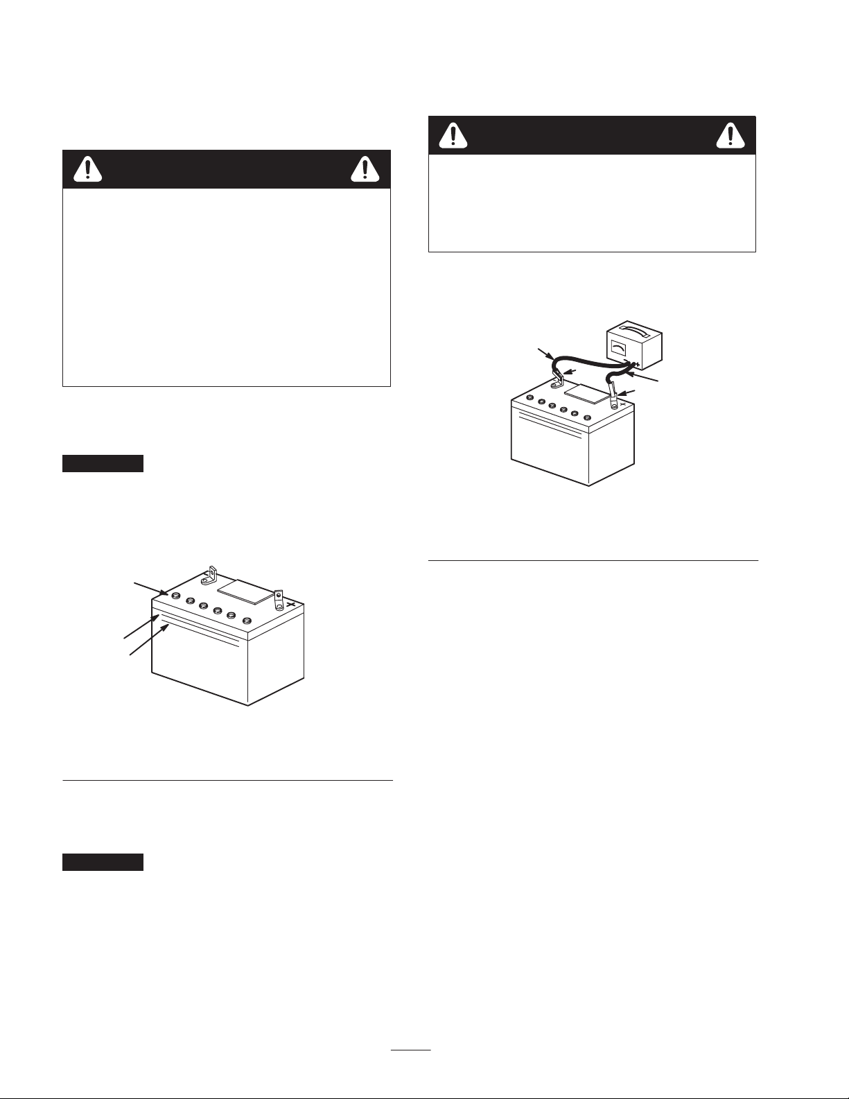
Warning
8. When the battery is fully charged, unplug the charger
from the electrical outlet, then disconnect the charger
leads from the battery posts (Fig. 11).
4
1
23
Figure 11
1. Positive post
2. Negative post 3. Charger red (+) wire
4. Charger black (–) wire
9. Install the battery in the tractor and connect the battery
cables; refer to Installing the Battery in the Operator’s
Manual.
Checking the Engine Oil Level
Before you start the engine and use the tractor, check the oil
level in the engine crankcase; refer to Checking the Oil
Level in the Operator’s Manual.
Filling the Fuel Tank
Add fuel to the fuel tank; refer to Filling the Fuel Tank in
the Operator’s Manual.
Checking the Tire Pressure
Check the front and rear tires for proper inflation; refer to
Checking the Tire Pressure in the Operator’s Manual.
Testing the Safety System
Test the safety interlock system; refer to The Safety
Interlock System in the Operator’s Manual.