Toro 30626 Groundsmaster 328-D User manual

Operator’s Manual
English (EN, GB)
Form No. 3359–382 Rev A
Groundsmaster 328-D
2 & 4 Wheel Drive Traction Units
Model No. 30626—280000001 and Up
Model No. 30627—280000001 and Up
Model No. 30630—280000001 and Up
Model No. 30631—280000001 and Up

2
All Rights Reserved
Printed in the USA
W2008 by The Toro Company
8111 Lyndale Avenue South
Bloomington, MN 55420-1196
The engine exhaust from this product contains
chemicals known to the State of California to cause
cancer, birth defects, or other reproductive harm.
Warning
Important The engine in this product is not equipped
with a spark arrester muffler. It is a violation of California
Public Resource Code Section 4442 to use or operate this
engine on any forest-covered, brush-covered, or
grass-covered land as defined in CPRC 4126. Other states
or federal areas may have similar laws.
Contents
Page
Introduction 3. . . . . . . . . . . . . . . . . . . . . . . . . . . . . . . .
Safety 3. . . . . . . . . . . . . . . . . . . . . . . . . . . . . . . . . . . . .
Safe Operating Practices 4. . . . . . . . . . . . . . . . . . . .
Toro Riding Mower Safety 6. . . . . . . . . . . . . . . . . .
Sound Power Level 7. . . . . . . . . . . . . . . . . . . . . . .
Sound Pressure Level 7. . . . . . . . . . . . . . . . . . . . . .
Vibration Level 7. . . . . . . . . . . . . . . . . . . . . . . . . . .
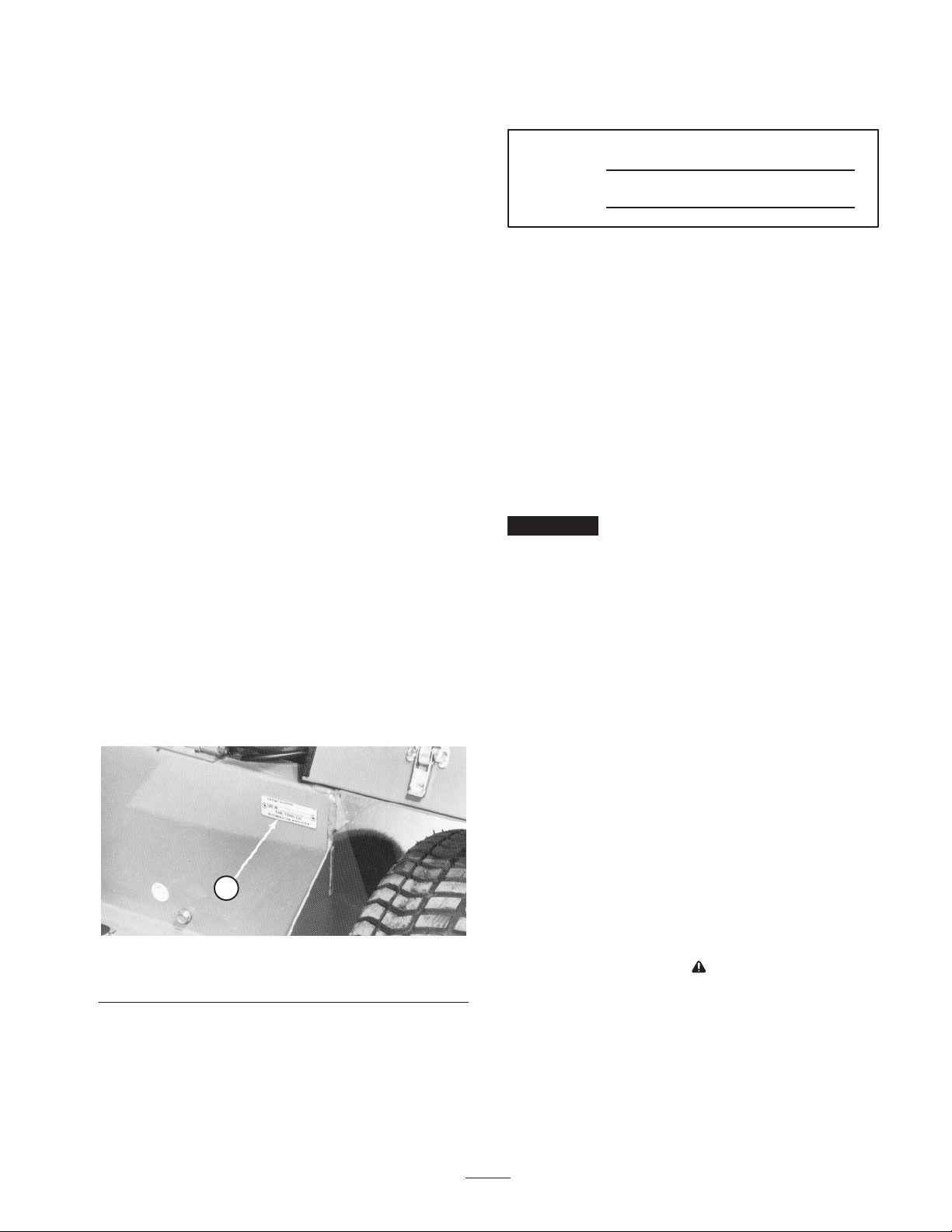
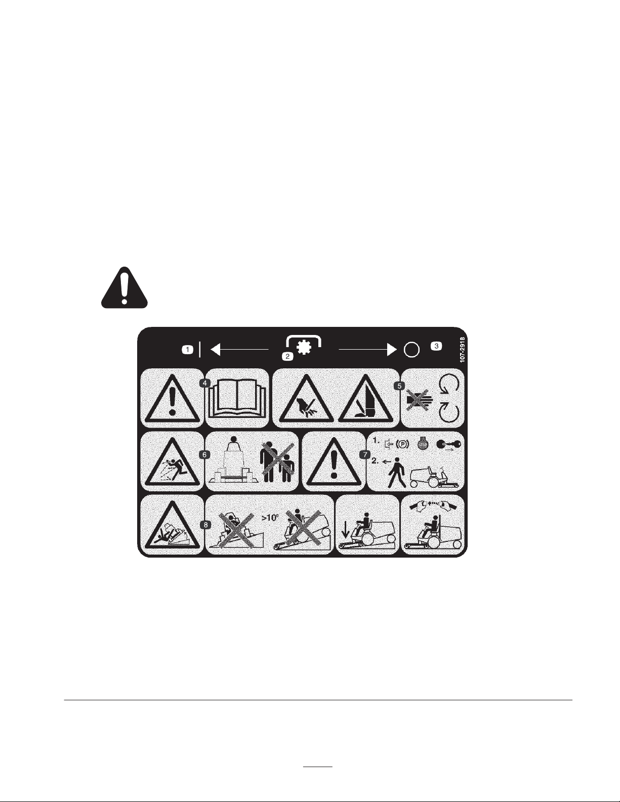
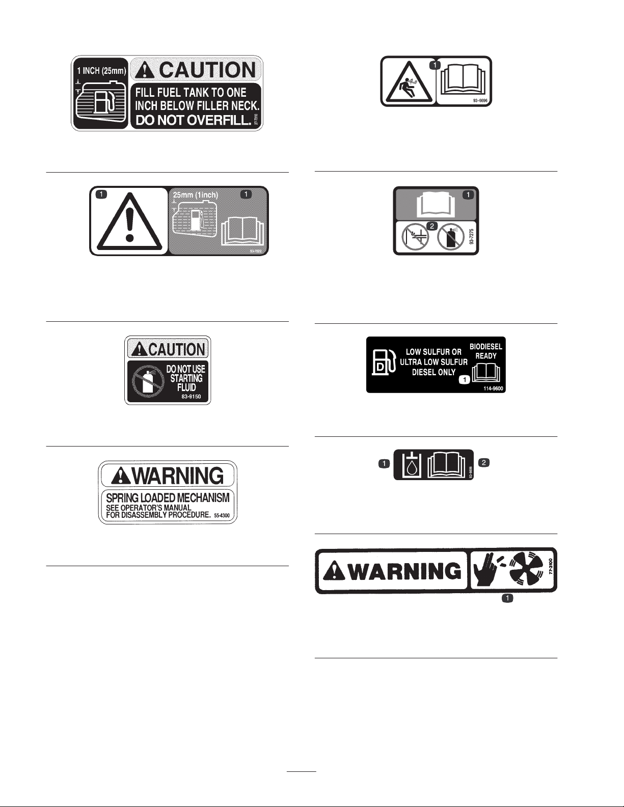
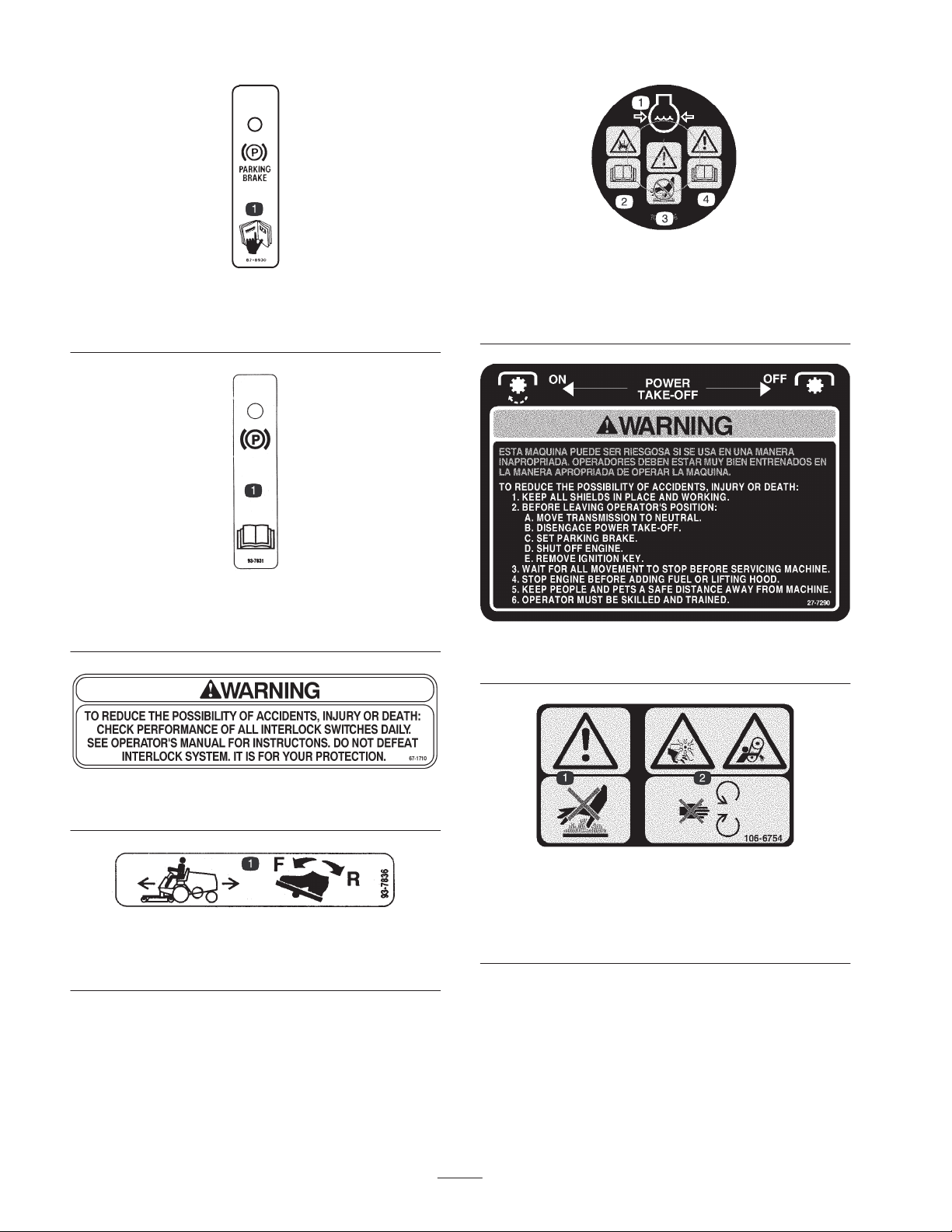
Safety and Instruction Decals 7. . . . . . . . . . . . . . . .
Specifications 13. . . . . . . . . . . . . . . . . . . . . . . . . . . . . . .
General Specifications 13. . . . . . . . . . . . . . . . . . . . .
Dimensions and Weights (approx.) 14. . . . . . . . . . .
Attachments/Accessories 14. . . . . . . . . . . . . . . . . . .
Setup 15. . . . . . . . . . . . . . . . . . . . . . . . . . . . . . . . . . . . .
Loose Parts 15. . . . . . . . . . . . . . . . . . . . . . . . . . . . . .
Installing the Steering Cylinder
(Models 30627 & 30631 only) 16. . . . . . . . . . . . .
Installing the Tie Rod
(Models 30627 & 30631 only) 16. . . . . . . . . . . . .
Installing the Rear Bumper
(Models 30627 & 30631 only) 16. . . . . . . . . . . . .
Installing the Front and Rear Wheels 16. . . . . . . . . .
Removing the Battery from the Chassis 16. . . . . . . .
Installing the Seat 17. . . . . . . . . . . . . . . . . . . . . . . . .
Installing the Seat Belt 18. . . . . . . . . . . . . . . . . . . . .
Installing the Roll Bar 19. . . . . . . . . . . . . . . . . . . . .
Pushing the Traction Unit Off of the Pallet 19. . . . .
Activating and Charging the Battery 19. . . . . . . . . .
Installing the Battery in the Chassis 20. . . . . . . . . . .
Installing the Ball Joint and Connecting the Lift
Cylinder 21. . . . . . . . . . . . . . . . . . . . . . . . . . . . . . .
Checking the Tire Pressure 21. . . . . . . . . . . . . . . . . .
Checking the Torque of the Front Wheel Nuts 22. . .
Greasing the Traction Unit 22. . . . . . . . . . . . . . . . . .
Install Rear Weight 22. . . . . . . . . . . . . . . . . . . . . . . .
Before Operating 23. . . . . . . . . . . . . . . . . . . . . . . . . . . .
Hood Prop
(Models 30626 & 30627 only) 23. . . . . . . . . . . . .
Checking the Crankcase Oil 23. . . . . . . . . . . . . . . . .
Filling the Fuel Tank 24. . . . . . . . . . . . . . . . . . . . . .
Check Cooling System 24. . . . . . . . . . . . . . . . . . . . .
Checking the Hydraulic System Fluid 25. . . . . . . . .
Checking the Hydraulic System 25. . . . . . . . . . . . . .
Checking the Rear Axle 26. . . . . . . . . . . . . . . . . . . .
Check Bidirectional Clutch Lubricant
(Models 30627 & 30631 only) 26. . . . . . . . . . . . .
Operation 27. . . . . . . . . . . . . . . . . . . . . . . . . . . . . . . . . .
Controls 27. . . . . . . . . . . . . . . . . . . . . . . . . . . . . . . .
Starting/Stopping Engine 29. . . . . . . . . . . . . . . . . . .
Bleeding Fuel System 29. . . . . . . . . . . . . . . . . . . . . .
Checking the Interlock Switches 30. . . . . . . . . . . . .
Pushing or Towing the Traction Unit 30. . . . . . . . . .
Operating Characteristics 31. . . . . . . . . . . . . . . . . . .
Maintenance 32. . . . . . . . . . . . . . . . . . . . . . . . . . . . . . . .
Recommended Maintenance Schedule 32. . . . . . . . .
Daily Maintenance Checklist 33. . . . . . . . . . . . . . . .
Lubricating the Machine 34. . . . . . . . . . . . . . . . . . .
General Air Cleaner Maintenance 35. . . . . . . . . . . .
Servicing Air Cleaner 35. . . . . . . . . . . . . . . . . . . . . .
Cleaning the Radiator and Screen 36. . . . . . . . . . . .
Changing Engine Oil And Filter 36. . . . . . . . . . . . . .
Servicing Fuel System 37. . . . . . . . . . . . . . . . . . . . .
Bleeding Air From Injectors 38. . . . . . . . . . . . . . . . .
Cleaning Radiator And Screen 38. . . . . . . . . . . . . . .
Changing Coolant In Cooling System 38. . . . . . . . .
Servicing the Engine Belts 39. . . . . . . . . . . . . . . . . .
Adjusting Throttle 40. . . . . . . . . . . . . . . . . . . . . . . .
Adjusting Traction Control Rod 40. . . . . . . . . . . . . .
Adjusting Traction Pedal Friction Wheel 41. . . . . . .
Adjusting the Traction Drive for Neutral 41. . . . . . .
Adjusting the Traction Interlock Switch 41. . . . . . . .
Replacing the PTO Switch 41. . . . . . . . . . . . . . . . . .
Adjusting PTO Drive Belt Tension 42. . . . . . . . . . . .
Adjusting the Parking Brake Interlock Switch 42. . .
Adjusting the Tilt Steering Control 43. . . . . . . . . . .
Adjusting Rear Wheel Toe–in
(Models 30627 & 30631 only) 43. . . . . . . . . . . . .
Adjusting Rear Wheel Toe–in
(Models 30626 & 30630 only) 43. . . . . . . . . . . . .
Adjusting Steering Stops
(Models 30627 & 30631 only) 44. . . . . . . . . . . . .
Adjusting the Rear Wheel Bearings
(Models 30626 & 30630 only) 44. . . . . . . . . . . . .
Adjusting the Brakes 44. . . . . . . . . . . . . . . . . . . . . .
Replacing the Hydraulic Fluid Filter 46. . . . . . . . . .
Changing the Hydraulic System Fluid 46. . . . . . . . .

3
Changing Rear Axle Lubricant 47. . . . . . . . . . . . . . .
Checking Steering Cylinder Bolt Torque
(Models 30627 & 30631 only) 47. . . . . . . . . . . . .
Changing Bidirectional Clutch Lubricant
(Models 30627 & 30631 only) 48. . . . . . . . . . . . .
Fuses 48. . . . . . . . . . . . . . . . . . . . . . . . . . . . . . . . . . .
Servicing the Battery 48. . . . . . . . . . . . . . . . . . . . . .
Hydraulic Schematic
(Models 30627 & 30631 only) 49. . . . . . . . . . . . .
Hydraulic Schematic
(Models 30626 & 30630 only) 50. . . . . . . . . . . . .
Electrical Schematic
(Models 30627 & 30631 only) 51. . . . . . . . . . . . .
Electrical Schematic
(Models 30626 & 30630 only) 52. . . . . . . . . . . . .
Seasonal Storage 53. . . . . . . . . . . . . . . . . . . . . . . . . . . .
Traction Unit 53. . . . . . . . . . . . . . . . . . . . . . . . . . . .
Engine 53. . . . . . . . . . . . . . . . . . . . . . . . . . . . . . . . . .
The Toro General Commercial Products Warranty 56. .
Introduction
Read this manual carefully to learn how to operate and
maintain your product properly. The information in this
manual can help you and others avoid injury and product
damage. Although Toro designs and produces safe
products, you are responsible for operating the product
properly and safely.
Whenever you need service, genuine Toro parts, or
additional information, contact an Authorized Service
Dealer or Toro Customer Service and have the model and
serial numbers of your product ready. Figure 1 illustrates
the location of the model and serial numbers on the
product.
1
Figure 1
1. Location of the model and serial numbers
Write the product model and serial numbers in the space
below:
Model No.
Serial No.
This manual identifies potential hazards and has special
safety messages that help you and others avoid personal
injury and even death. Danger, Warning, and Caution are
signal words used to identify the level of hazard. However,
regardless of the hazard, be extremely careful.
Danger signals an extreme hazard that will cause serious
injury or death if you do not follow the recommended
precautions.
Warning signals a hazard that may cause serious injury or
death if you do not follow the recommended precautions.
Caution signals a hazard that may cause minor or moderate
injury if you do not follow the recommended precautions.
This manual uses two other words to highlight information.
Important calls attention to special mechanical
information and Note: emphasizes general information
worthy of special attention.
Safety
Models 30630 and 30631 meet or exceed CEN standard
EN 836:1997, ISO standard 5395:1990, and ANSI
B71.4-2004 specifications in effect at the time of
production, when weights are installed according to
chart on page 24.
Models 30626 and 30627 meet or exceed the B71.4 2004
specifications of the American National Standards
Institute, in effect at time of production, when weights
are installed according to chart on page 24.
Note: The addition of attachments made by other
manufacturers that do not meet American National
Standards Institute certification will cause noncompliance
of this machine.
Improper use or maintenance by the operator or owner
can result in injury. To reduce the potential for injury,
comply with these safety instructions and always pay
attention to the safety alert symbol, which means
CAUTION, WARNING, or DANGER—“personal
safety instruction.” Failure to comply with the
instruction may result in personal injury or death.

4
Safe Operating Practices
The following instructions are from the CEN standard EN
836:1997, ISO standard 5395:1990, and ANSI B71.4-2004.
Training
•Read the operator’s manual and other training material
carefully. Be familiar with the controls, safety signs,
and the proper use of the equipment.
•If the operator or mechanic can not read the language of
is the owner’s responsibility to explain this material to
them.
•Never allow children or people unfamiliar with these
instructions to use or service the mower. Local
regulations may restrict the age of the operator.
•Never mow while people, especially children, or pets
are nearby.
•Keep in mind that the operator or user is responsible for
accidents or hazards occurring to other people or their
property.
•Do not carry passengers.
•All drivers and mechanics should seek and obtain
professional and practical instruction. The owner is
responsible for training the users. Such instruction
should emphasize:
– the need for care and concentration when working
with ride-on machines;
– control of a ride-on machine sliding on a slope will
not be regained by the application of the brake. The
main reasons for loss of control are:
•insufficient wheel grip;
•being driven too fast;
•inadequate braking;
•the type of machine is unsuitable for its task;
•lack of awareness of the effect of ground
conditions, especially slopes;
•incorrect hitching and load distribution.
•The owner/user can prevent and is responsible for
accidents or injuries occurring to himself or herself,
other people, or property.
Preparation
•While mowing, always wear substantial footwear, long
trousers, hard hat, safety glasses, and hearing
protection. Long hair, loose clothing, or jewelry may
get tangled in moving parts. Do not operate the
equipment when barefoot or wearing open sandals.
•Thoroughly inspect the area where the equipment is to
be used and remove all objects which may be thrown by
the machine.
•Warning—Fuel is highly flammable. Take the
following precautions:
– Store fuel in containers specifically designed for this
purpose.
– Refuel outdoors only and do not smoke while
refueling.
– Add fuel before starting the engine. Never remove
the cap of the fuel tank or add fuel while the engine
is running or when the engine is hot.
– If fuel is spilled, do not attempt to start the engine
but move the machine away from the area of
spillage and avoid creating any source of ignition
until fuel vapors have dissipated.
– Replace all fuel tanks and container caps securely.
•Replace faulty silencers/mufflers.
•Evaluate the terrain to determine what accessories and
attachments are needed to properly and safely perform
the job. Only use accessories and attachments approved
by the manufacturer.
•Check that operator’s presence controls, safety switches
and shields are attached and functioning properly. Do
not operate unless they are functioning properly.
Operation
•Do not operate the engine in a confined space where
dangerous carbon monoxide fumes can collect.
•Mow only in daylight or in good artificial light.
•Before attempting to start the engine, disengage all
blade attachment clutches, shift into neutral, and engage
the parking brake.
•Do not put hands or feet near or under rotating parts.
Keep clear of the discharge opening at all times.
•Remember there is no such thing as a safe slope. Travel
on grass slopes requires particular care. To guard
against overturning:
– do not stop or start suddenly when going up or
downhill;
– engage clutch slowly, always keep machine in gear,
especially when travelling downhill;
– machine speeds should be kept low on slopes and
during tight turns;
– stay alert for humps and hollows and other hidden
hazards;
– never mow across the face of the slope, unless the
mower is designed for this purpose.

5
•Stay alert for holes in the terrain and other hidden
hazards.
•Use care when pulling loads or using heavy equipment.
– Use only approved drawbar hitch points.
– Limit loads to those you can safely control.
– Do not turn sharply. Use care when reversing.
– Use counterweight(s) or wheel weights when
suggested in the operator’s manual.
•Watch out for traffic when crossing or near roadways.
•Stop the blades rotating before crossing surfaces other
than grass.
•When using any attachments, never direct discharge of
material toward bystanders nor allow anyone near the
machine while in operation.
•Never operate the machine with damaged guards,
shields, or without safety protective devices in place. Be
sure all interlocks are attached, adjusted properly, and
functioning properly.
•Do not change the engine governor settings or
overspeed the engine. Operating the engine at excessive
speed may increase the hazard of personal injury.
•Before leaving the operator’s position:
– stop on level ground;
– disengage the power take-off and lower the
attachments;
– change into neutral and set the parking brake;
– stop the engine and remove the key.
•Disengage drive to attachments when transporting or
not in use.
•Stop the engine and disengage drive to attachment
– before refuelling;
– before removing the grass catcher/catchers;
– before making height adjustment unless adjustment
can be made from the operator’s position.
– before clearing blockages;
– before checking, cleaning or working on the mower;
– after striking a foreign object or if an abnormal
vibration occurs. Inspect the mower for damage and
make repairs before restarting and operating the
equipment.
•Reduce the throttle setting during engine run-out and, if
the engine is provided with a shut-off valve, turn the
fuel off at the conclusion of mowing.
•Keep hands and feet away from the cutting units.
•Look behind and down before backing up to be sure of
a clear path.
•Slow down and use caution when making turns and
crossing roads and sidewalks. Stop cutting units if not
mowing.
•Be aware of the mower discharge direction and do not
point it at anyone.
•Do not operate the mower under the influence of
alcohol or drugs
•Use care when loading or unloading the machine into a
trailer or truck
•Use care when approaching blind corners, shrubs, trees,
or other objects that may obscure vision.
Maintenance and Storage
•Keep all nuts, bolts and screws tight to be sure the
equipment is in safe working condition.
•Never store the equipment with fuel in the tank inside a
building where fumes may reach an open flame or
spark.
•Allow the engine to cool before storing in any
enclosure.
•To reduce the fire hazard, keep the engine,
silencer/muffler, battery compartment and fuel storage
area free of grass, leaves, or excessive grease.
•Check the grass catcher frequently for wear or
deterioration.
•Keep all parts in good working condition and all
hardware and hydraulic fittings tightened. Replace all
worn or damaged parts and decals.
•If the fuel tank has to be drained, do this outdoors.
•Be careful during adjustment of the machine to prevent
entrapment of the fingers between moving blades and
fixed parts of the machine.
•On multi-spindle mowers, take care as rotating one
blade can cause other blades to rotate.
•Disengage drives, lower the cutting units, set parking
brake, stop engine and remove key and disconnect spark
plug wire. Wait for all movement to stop before
adjusting, cleaning or repairing.
•Clean grass and debris from cutting units, drives,
silencers/mufflers, and engine to help prevent fires.
Clean up oil or fuel spillage.
•Use jack stands to support components when required.
•Carefully release pressure from components with stored
energy.

6
•Disconnect battery and remove spark plug wire before
making any repairs. Disconnect the negative terminal
first and the positive last. Reconnect positive first and
negative last.
•Keep hands and feet away from moving parts. If
possible, do not make adjustments with the engine
running.
•Charge batteries in an open well ventilated area, away
from spark and flames. Unplug charger before
connecting or disconnecting from battery. Wear
protective clothing and use insulated tools.
Toro Riding Mower Safety
The following list contains safety information specific to
Toro products or other safety information that you must
know that is not included in the CEN, ISO, or ANSI
standard.
This product is capable of amputating hands and feet and
throwing objects. Always follow all safety instructions to
avoid serious injury or death.
Use of this product for purposes other than its intended use
could prove dangerous to user and bystanders.
Engine exhaust contains carbon monoxide, which
is an odorless, deadly poison that can kill you.
Do not run engine indoors or in an enclosed area.
Warning
•Know how to stop the engine quickly.
•Do not operate the machine while wearing tennis shoes
or sneakers.
•Wearing safety shoes and long pants is advisable and
required by some local ordinances and insurance
regulations.
•Handle fuel carefully. Wipe up any spills.
•Check the safety interlock switches daily for proper
operation. If a switch should fail, replace the switch
before operating the machine.
•Before starting the engine, sit on the seat.
•Using the machine demands attention. To prevent loss
of control:
– Do not drive close to sand traps, ditches, creeks, or
other hazards.
– Reduce speed when making sharp turns. Avoid
sudden stops and starts.
– This machine is not designed or equipped for
on–road use and is a “slow–moving vehicle.” If you
must cross or travel on a public road, you should be
aware of and comply with local regulations, such as
required lights, slow moving vehicle signs, and
reflectors.
– Apply the service brakes when going downhill to
keep forward speed slow and to maintain control of
the machine.
•Raise the cutting units when driving from one work
area to another.
•Do not touch the engine, silencer/muffler, or exhaust
pipe while the engine is running or soon after it has
stopped because these areas could be hot enough to
cause burns.
•If the engine stalls or loses headway and cannot make it
to the top of a slope, do not turn the machine around.
Always back slowly, straight down the slope.
•When a person or pet appears unexpectedly in or near
the mowing area, stop mowing. Careless operation,
combined with terrain angles, ricochets, or improperly
positioned guards can lead to thrown object injuries. Do
not resume mowing until the area is cleared.
Maintenance and Storage
•Make sure all hydraulic line connectors are tight and all
hydraulic hoses and lines are in good condition before
applying pressure to the system.
•Keep your body and hands away from pin hole leaks or
nozzles that eject hydraulic fluid under high pressure.
Use paper or cardboard, not your hands, to search for
leaks. Hydraulic fluid escaping under pressure can have
sufficient force to penetrate the skin and cause serious
injury. Seek immediate medical attention if fluid is
injected into skin.
•Before disconnecting or performing any work on the
hydraulic system, all pressure in the system must be
relieved by stopping the engine and lowering the cutting
units and attachments to the ground.
•Check all fuel lines for tightness and wear on a regular
basis. Tighten or repair them as needed.
•If the engine must be running to perform a maintenance
adjustment, keep hands, feet, clothing, and any parts of
the body away from the cutting units, attachments, and
any moving parts, especially the screen at the side of the
engine. Keep everyone away.
•To ensure safety and accuracy, have an Authorized Toro
Distributor check the maximum engine speed with a
tachometer. Maximum governed engine speed should be
3250 RPM.

7
•If major repairs are ever needed or if assistance is
desired, contact an Authorized Toro Distributor.
•Use only Toro-approved attachments and replacement
parts. The warranty may be voided if used with
unapproved attachments.
Sound Power Level
This unit has a guaranteed sound power level of 105 dBA,
based on measurements of identical machines per ISO
11094.
Sound Pressure Level
This unit has an equivalent continuous A-weighted sound
pressure level at the operator ear of 89 dBA based on
measurements of identical machines per EN 836 and ISO
11201.
Vibration Level
This unit does not exceed a hand/vibration level of 2.5 m/s2
based on measurements of identical machines per EN 836
and EN 1033.
This unit does not exceed a whole body/vibration level of
0.5 m/s2based on measurements of identical machines per
EN 836 and EN 1032.
Safety and Instruction Decals
Safety decals and instructions are easily visible to the operator and are located near any area
of potential danger. Replace any decal that is damaged or lost.
107-2918
(Models 30630 & 30631)
*This safety decal includes aslope warning required on the machine for compliance to the European Lawn Mower Safety Standard
EN836:1997. The conservative maximum slope angles indicated for operation of this machine are prescribed by and required by this
standard.
1. On
2. Power take-off (PTO)
3. Off
4. Warning—read the
Operator’s Manual.
5. Cutting hazard of hand or
foot—stay away from
moving parts.
6. Thrown object hazard—keep
bystanders a safe distance
from the machine.
7. Warning—lock the parking
brake, stop the engine, and
remove the ignition key
before leaving the machine.
8. Tipping hazard—do not drive
the machine on a slope
greater than 10 degrees,
lower the cutting unit when
driving down slopes, and if
the roll bar is installed, wear
the seat belt.

8
27-7310
(Models 30626 & 30627)
93-7822
(Models 30630 & 30631)
1. Caution—fill fuel tank to 1 in. (25 mm) below filler neck. Read
the operator’s manual for further instructions.
83-9150
(Models 30626 & 30627)
55-4300
(Models 30626 & 30627)
93-6696
(Models 30630 & 30631)
1. Warning—spring loaded mechanism. Read the operator’s
manual for further instructions.
93-7275
(Models 30630 & 30631)
1. Read the operator’s manual for further instructions.
2. Do not use starting fluid.
114-9600
1. Read the Operator’s Manual.
93-6686
1. Hydraulic oil 2. Read the Operator’s
Manual.
77–3100
(Models 30626 & 30627)
1. Fan blades can cause injury—stay away from moving parts.

9
93-7272
(Model 30630 & 30631)
1. Fan blades can cause injury—stay away from moving parts.
82-8940
1. Locks and unlocks the steering column
105-0056
1. Fast
2. Slow
3. Engine stop
4. Engine run
5. Engine start
6. Temperature
93-7830
1. Caution—read the operator’s manual for further instructions.
2. Wheel torque specifications
105-2531
(Models 30626 & 30627)
107-2927
(Models 30630 &30631)
1. To start the engine, read the Operator’s Manual, disengage the
power take–off (PTO), place the traction drive in neutral, press
the brake, move the throttle lever to the Fast position, turn the
key to the Engine—power position until the glow plug light
illuminates, and then turn the key to the Engine—start position.
2. To over-ride the engine temperature warning, press the button.

10
82-8930
(Model 30626 & 30627)
1. Read the operator’s manual for further instructions.
93-7831
1. Parking brake—read the operator’s manual for further
instructions.
67–1710
(Model s 30626 & 30627)
93-7836
1. To move the traction unit forward or backward, depress the
traction pedal.
106-5976
1. Engine coolant under
pressure
2. Explosion hazard—read
the Operator’s Manual.
3. Warning—do not touch
the hot surface.
4. Warning—read the
Operator’s Manual.
27-7290
(Models 30626 & 30627)
106-6754
(Models 30630 & 30631)
1. Warning—do not touch the hot surface.
2. Cutting/dismemberment hazard, fan and entanglement hazard,
belt—stay away from moving parts

11
72-3700
(Model 30627 & 30626)
93-7839
(Model 30630 & 30631)
*This safety decal includes aslope warning required on the
machine for compliance to the European Lawn Mower Safety
Standard EN836:1997. The conservative maximum slope
angles indicated for operation of this machine are prescribed
by and required by this standard.
1. Warning—read the Operator’s Manual.
2. Tipping hazard—do not drive the machine on a slope greater
than 10 degrees; when driving down slopes, lower the cutting
unit, and if the roll bar is installed, wear the seat belt.
70-2560
(Model 30627)
93–6697
(Model 30631)
1. Read operator manual
2. Change the rear axle lubricant initially after first 50 operating
hours, thereafter every 500 hours
106-8120
(Models 30626 & 30627)
1. Thrown object
hazard—keep bystanders
a safe distance from the
machine.
2. Cutting hazard of hand
and foot—stay away from
moving parts.
Battery Symbols
Some or all of these symbols are on your battery.
1. Explosion hazard
2. No fire, open flames, or
smoking.
3. Caustic liquid/chemical
burn hazard
4. Wear eye protection
5. Read the Operator’s
Manual.
6. Keep bystanders a safe
distance from the battery.
7. Wear eye protection;
explosive gases can
cause blindness and
other injuries
8. Battery acid can cause
blindness or severe
burns.
9. Flush eyes immediately
with water and get
medical help fast.
10. Contains lead; do not
discard.

12
105-7823
(Models 30630 & 30631)
1. Traction drive—to drive
forward, press the top of
the traction control pedal
forward and down; to
drive in reverse, press the
bottom of the traction
control pedal rearward
and down.
2. Warning—disengage the
power take-off (PTO)
before raising the cutting
unit(s).
3. Float the cutting unit(s)
over the ground.
4. Lower the cutting unit(s).
5. Raise the cutting unit(s).
105-7822
(Models 30626 & 30627)
Manufacturers Mark
1. Indicates the blade is identified as a part from the original
machine manufacturer.

13
Specifications
Note: Specifications and design subject to change without notice.
General Specifications
Engine Kubota, three cylinder, 4 cycle liquid cooled diesel engine. 26 hp @ 3000. Engine
high idle is 3100–3250 rpm, low idle is 1500–1650 rpm.
Air Cleaner Heavy duty, remote mounted
Muffler Volume equal to approximately five times engine displacement for excellent
silencing.
Cooling System
Radiator has tube and fin construction with hydraulic oil cooler in lower tank.
Capacity of cooling system is approximately 6 quarts (5.7 l) of a 50% mixture of
permanent, ethylene glycol anti-freeze and water.
Electrical
12 volt battery has 630 amp., cold cranking performance at 0°F (–18°C). Fuse
block located under the control panel. Starter relay interlock circuit for maximum
current hold–in of starter solenoid in low voltage conditions
Fuel System Fuel tank capacity is approximately 6-1/2 gal. (25 l). 12 volt, electric fuel pump .
Fuel filter/water separator with replaceable cartridge is mounted on frame.
Front Axle
The heavy duty Dana GT 20 axle has reduction of 20:9:1. Axle has automotive type
differential, bevel gear pinion and ring gear with spur gear reduction from
transmission. All axle components are mounted in tapered roller bearings.
Rear Axle
(Models 30627 & 30631)
The rear axle is mechanically driven from the front axle by a universal shaft. Axle
has a bidirectional – overrunning clutch in rear driveshaft. When lubricating rear
axle, use SAE 80W-90 gear lube, API GL-5. Lubricant capacity is approximately
2.2 qt. (2.1 L).
Transmission
The in-line hydrostatic transmission is mounted directly to the front axle and is
driven by flexible drive couplings. Operating pressure is 500 to 3000 psi (3447 to
20685 kPa) and normal charge pressure is 70 to 150 psi (453 to 1034 kPa).
Implement relief valve setting is 700 to 900 psi (4826 to 6205 kPa). Displacement is
0.913 cubic inch (15 cm3) per revolution, and transmission is controlled by
foot-actuated pedal. Front axle is the hydraulic fluid reservoir, and its capacity is 5
quarts (4.7 l). The 25 micron hydraulic filter is a screw on replaceable type. For
replacement filters, order Toro Part No. 23-9740.
Ground Speed Speed is infinitely variable from 0 to 9.5 MPH (0 to 15 km/h) forward or reverse.
Tires
Two rear tires are 18 x 6.50-8 (4 wheel drive) and 16 x 6.50–8 (2 wheel drive),
4-ply, extra traction tread, on demountable, drop center wheels. The two front tires
are 23 x 8.50-12, extra traction tread, 4-ply rating, on demountable, drop center
wheels. Recommended air pressure for both the front and rear tires is 21 psi (145
kPa).
Brakes
Brakes controlled by 3 pedals. Two are for steering assist. Are individually
controlled by left foot. Third pedal operates both brakes; is controlled by either foot.
Parking brake latch provided for third pedal. Pedals are connected to brakes by
multi-stranded cable and conduit.
Steering
The 13 inch (33 cm) steering wheel is mounted on a steering valve consisting of a
control valve and metering section which regulates pressure and meters flow to the
steering cylinder. Minimum turning radius is 18 in. from center of turn to closest side
of drive wheel; however, zero turning radius results when individual wheel brakes
are used. Steering wheel adjustable fore and aft for operator comfort.
Main Frame Frame is welded, formed 11 ga. steel, reinforced with square and rectangular
tubing.

14
General Specifications (continued)
Interlock Switches
PTO switch—shuts engine off when PTO is engaged with no operator in seat.
Traction switch—shuts engine off when traction pedal is engaged with no operator
in seat. Seat switch—shuts engine off if operator leaves seat without disengaging
PTO and/or traction pedal. Engine will not start if PTO or traction pedal is engaged.
Brake switch–shuts engine off when PTO or traction pedal is engaged with parking
brake set.
Instrument Panel and
Control
Hour meter, fuel gauge, ignition switch, oil pressure warning light, charge indicator,
engine coolant temperature warning light, temperature gauge, temperature override
switch, glow plug indicator light and throttle control are on instrument panel. Hand
operated PTO lever is located to right of the seat. Traction pedal for traction
operation at right of steering column.
PTO Drive
Shaft is driven by a tight-slack double “A” section, torque team V-belt directly from
output shaft of engine. Shaft is clutched by pivoting the shaft support with a spring
loaded, over center, hand operated lever. PTO speed 1810 RPM @ 3200 RPM
engine speed. Connection to implement is with high quality, needle bearing
universal joint with slip joint.
Implement Lift Cutting unit or implement is lifted by hydraulic cylinder that has 2-1/2 in. (64 mm)
bore and 3-1/4 in. (82 mm) stroke.
Dimensions and Weights
(approx.)
Width (measured from
outside of front tires)
46 in. (117 cm)
Length 91 in. (231 cm)
Height 50 in. (127 cm)
Height w/ROPS 78.5 in. (199 cm)
Dry Weight – 2 Wheel
Drive w cutter deck
1650 lb. (743 kg)
Dry Weight – 4 Wheel
Drive
2065 lb. (929 kg)
Wheel Base 49 in. (124 cm)
Attachments/Accessories
A selection of Toro approved attachments and accessories
are available for use with the machine to enhance and
expand its capabilities. Contact your Authorized Service
Dealer or Distributor or go to www.Toro.com for a list of
all approved attachments and accessories.

15
Setup
Note: Determine the left and right sides of the machine from the normal operating position.
Loose Parts
Note: Use the chart below to verify that all parts have been shipped.
Description Qty. Use
Screw, M10 x 30 mm
Washer
4
4
Mounting steering cylinder to rear axle.
(Models 30627 & 30631 only)
Tie rod 1Mount to steering arms.
(Models 30627 & 30631 only)
Bumper 1 Mount to axle support.
(Models 30627 & 30631 only)
Capscrew, 1/4 x 1/2 in.
Flange nut 1/4 in.
1
1
Secure steering hoses to bumper.
(Models 30627 & 30631 only)
Rear wheel 2Mounting rear steering wheels (Metric nuts)
Front wheel 2Mounting front wheels (English nuts)
Manual tube (shipped in tool box)
R-clamp
1
2
Holding the operator’s manual. Install on right
underside of seat.
Seat belt
Bolt, 7/16 x 1 in.
Lock washer, 7/16 in.
1
2
2
Installing the seat belts
Roll Bar (ROPS)
Bolt, 3/4 x 5-1/2 in.
Lock washer, 3/4 in.
Nut, 3/4 in.
1
4
4
4
Installing the roll bar
Right-hand ball joint (shipped in tool box) 1Install ball joint (implement installation) and
connect lift cylinder
Hydraulic oil filter 1Change after 10 hours
Parts catalog 1
Operator’s Manual (traction unit)
Models 30627/30626 2Read before operating the machine.
Operator’s Manual (traction unit)
Models 30631/30630 1Read before operating the machine.
Operator Training Material (Models 30626/30627
only) 1Watch before operating the machine.
Certificate of Quality 1
Note: Some models may have already been set–up at factory.

16
Installing the Steering Cylinder
(Models 30627 & 30631 only)
1. Remove screw and R-clamp securing steering cylinder
to packaging. Retain R-clamp for future installation.
2. Mount cylinder support bracket to rear of axle with 4
screws (M10 x 30) screws and washers (Fig. 2). Apply
Loctite 242, or equivalent, and torque screws to 48–60
ft.-lb. (65–81 N⋅m).
1
2
Figure 2
1. Cylinder support bracket 2. Steering arm
3. Remove castle nut and cotter pin from ball joint end of
steering cylinder. Insert ball joint end into center hole of
axle steering arm. Insert the ball joint from the top of
the steering arm.
4. Secure ball joint end to steering arm with castle nut
(Fig. 2) and torque it to 70–90 ft.-lb. (94–122 N⋅m).
Install cotter pin.
Installing the Tie Rod
(Models 30627 & 30631 only)
1. Remove cotter pins and castle nuts from ball joint ends
of tie rod. Insert ball joint ends into rear hole of each
axle steering arm. Insert ball joints from bottom of each
steering arm (Fig. 3).
1
Figure 3
1. Tie rod
2. Secure ball joint ends to steering arms with a castle nut
and torque it to 40–60 ft.-lb. (54–81 N⋅m). Install a
cotter pin.
Installing the Rear Bumper
(Models 30627 & 30631 only)
1. Remove 2 capscrews (1/2 x 3/4 in.), lock washers, and
flat washers securing rear weight to axle support
(Fig. 4).
1
2
3
4
Figure 4
1. Rear weight
2. Axle support
3. Bumper
4. R-clamp
2. Using capscrews, lock washers and flat washers
previously removed, mount bumper and rear weight to
axle support.
3. Using R-clamp previously removed, secure steering
hoses to axle support with a capscrew (1/4 x 1/2 in.) and
flange nut supplied, in loose parts.
Installing the Front and Rear
Wheels
1. Remove and discard fasteners securing wheels to
packaging.
2. Remove wheel nuts from studs on axles.
Note: Front wheel nuts are English and rear wheel nuts are
metric.
3. Mount wheels and torque mounting nuts to 45-55 ft.-lb.
(61-75 N⋅m).
Removing the Battery from the
Chassis
1. Release the two latches holding instrument cover in
place. Carefully remove instrument cover to expose the
battery.

17
2. Remove two wing nuts and hold down strap that secures
battery (Fig. 5). Lift battery out of chassis. Keep wing
nuts and hold down strap in safe place for later use.
121
3
4
Figure 5
1. Wing nuts
2. Hold down strap
3. Positive terminal
4. Negative terminal
Installing the Seat
The machine is shipped without the seat assembly. Either
optional Seat Kit, Model No. 30623 or 30625 must be
installed.
Seat Kit, Model No. 30623, Standard Seat
1. Loosely secure (2) R-clamps to right side of seat bottom
with 2 capscrews and flat washers supplied in kit
(Fig. 6). Install manual tube into R-clamps and tighten
capscrews (Fig. 6).
1
2
3
4
Figure 6
1. R-clamps
2. Seat support
3. Manual tube
4. Cap
2. Mount seat pivot bracket to frame with 2 flange screws
supplied in kit (Fig. 7)
1
Figure 7
1. Seat pivot bracket
3. Mount seat and seat support to seat pivot bracket with
pivot shaft and roll pin (Fig. 8).
1
2
Figure 8
1. Pivot shaft 2. Roll pin
4. Hold seat up with seat support rod (Fig. 9).
5. Plug wire harness connector into seat switch connector
on bottom of seat.
1
Figure 9
1. Seat support rod
6. Disengage seat support rod and pivot downward. Pivot
seat down and push lynch pin through seat latch stud.
Flip wire end of pin over latch stud (Fig. 10).

18
1
Figure 10
1. Lynch pin
7. Slide seat completely forward and backward to ensure
proper operation and that seat switch wires and
connectors are not pinched or do no contact any moving
parts.
Seat Kit, Model No. 30625, Deluxe Seat
with Model No. 30628 Seat Adapter Kit
1. Mount seat suspension assembly to 4 capscrews on seat
bottom and secure with 4 lock washers, flat washers,
and nuts (Fig. 11).
1
6
42
5
3
Figure 11
1. Seat suspension
assembly
2. R-clamps
3. Lock washer, flat washer,
and nut
4. Manual tube
5. Cap
6. Seat support
2. Loosely secure 2 R-clamps to right side of seat bottom
with 2 capscrews and flat washers supplied in kit
(Fig. 11). Install manual tube into R-clamps and tighten
capscrews (Fig. 11).
3. Mount seat support over four threaded studs at the
bottom of seat suspension assembly and secure in place
with flangenuts (Fig. 11).
4. Mount seat pivot bracket to frame with (2) flange
screws supplied in kit (Fig. 7)
5. Mount seat and seat support to seat pivot bracket with
pivot shaft and roll pin (Fig. 8).
6. Hold seat up with seat support rod (Fig. 9).
7. Route seat switch harness through holes in seat support
and seat suspension (Fig. 12). Plug wire harness
connector into seat switch connector on bottom of seat.
1
Figure 12
1. Seat switch wire harness
8. Disengage seat support rod and pivot downward. Pivot
seat down and push lynch pin through seat latch stud.
Flip wire end of pin over latch stud (Fig. 10).
9. Slide seat completely forward and backward to ensure
proper operation and that seat switch wires and
connectors are not pinched or do no contact any moving
parts.
Installing the Seat Belt
Install seat belt to holes in back of seat with 2 bolts
(7/16 x 1 in.) and lock washers (Fig. 13). Tighten securely.
Important Mount the latch side of the belt to the right
side of the seat.
1
Figure 13
1. Seat belt

19
Installing the Roll Bar
1. Lower roll bar onto frame, aligning mounting holes as
shown in Figure 14.
2. Secure roll bar to frame with 4 bolts (3/4 x 5-1/2 in.),
lock washers, and nuts (Fig. 14). Tighten securely.
1
Figure 14
1. Roll bar
Pushing the Traction Unit Off
of the Pallet
1. Reach in and rotate bypass valve on transmission
(Fig. 15) counterclockwise 1/2 to 1 turn. Opening the
valve opens an internal passage in the pump, thereby
bypassing transmission oil. Because fluid is bypassed,
the machine can be pushed without damaging the
transmission.
1
Figure 15
1. Bypass valve
2. Lift machine over shipping braces and push machine off
pallet.
3. Close bypass valve by rotating it clockwise until it is
securely seated. Do not exceed 5 to 8 ft.-lb. (7 to
11 N⋅m). Do not start engine when valve is open.
Activating and Charging the
Battery
Use only electrolyte (1.265 Specific Gravity) to fill battery
initially.
1. Remove the battery from the machine.
Important Do not add electrolyte while the battery is in
the machine. You could spill it, causing corrosion.
2. Clean the top of the battery and remove the vent caps
(Fig. 16).
1
Figure 16
1. Vent caps
3. Carefully fill each cell with electrolyte until the plates
are covered with about 1/4 inch (6 mm) of fluid.
1
Figure 17
1. Electrolyte

20
4. Allow approximately 20 to 30 minutes for the
electrolyte to soak into the plates. Refill as necessary to
bring the electrolyte to within about 1/4 inch (6 mm) of
the bottom of the fill well (Fig. 17).
Charging the battery produces gasses that can
explode.
Never smoke near the battery and keep sparks and
flames away from battery.
Warning
5. Connect a 3 to 4 amp battery charger to the battery
posts. Charge the battery at a rate of 3 to 4 amps until
the specific gravity is 1.250 or higher and the
temperature is at least 60_F (16_C) with all sells gasing
freely.
6. When the battery is charged, disconnect the charger
from the electrical outlet and battery posts.
Note: After the battery has been activated, add only
distilled water to replace normal loss, although
maintenance–free batteries should not require water under
normal operating conditions.
CALIFORNIA
Proposition 65 Warning
Battery posts, terminals, and related accessories
contain lead and lead compounds, chemicals
known to the State of California to cause cancer
and reproductive harm. Wash hands after
handling.
Warning
Battery terminals or metal tools could short
against metal tractor components causing sparks.
Sparks can cause the battery gasses to explode,
resulting in personal injury.
•When removing or installing the battery, do not
allow the battery terminals to touch any metal
parts of the tractor.
•Do not allow metal tools to short between the
battery terminals and metal parts of the tractor.
Warning
Installing the Battery in the
Chassis
Battery terminals or metal tools could short
against metal machine components causing sparks.
Sparks can cause the battery gasses to explode,
resulting in personal injury.
•When removing or installing the battery, do not
allow the battery terminals to touch any metal
parts of the machine.
•Do not allow metal tools to short between the
battery terminals and metal parts of the
machine.
Warning
1. Install battery and secure with hold down strap and
wing nuts (Fig. 5).Remove tape over ends of each
cable.
2. Slide the red, positive battery cable (Fig. 5) onto
positive battery post and tighten nut securely.
Incorrect battery cable routing could damage the
machine and cables causing sparks. Sparks can
cause the battery gasses to explode, resulting in
personal injury.
•Always disconnect the negative (black) battery
cable before disconnecting the positive (red)
cable.
•Always connect the positive (red) battery cable
before connecting the negative (black) cable.
Warning
3. Slide the black, negative battery cable (Fig. 5) onto
negative battery post and tighten nut securely.
4. Coat both battery connections with either Grafo 112X
(skin-over) grease, Toro Part No. 505-47, petroleum
jelly or light grease to prevent corrosion and slide
rubber boot over positive terminal (Fig. 5).
5. Install the instrument cover and lock the two latches.
Other manuals for 30626 Groundsmaster 328-D
2
This manual suits for next models
4
Table of contents
Other Toro Lawn Mower manuals

Toro
Toro Greensmaster 3150 User manual

Toro
Toro Recycler 20998 User manual

Toro
Toro 22298 User manual

Toro
Toro GrandStand 74534 User manual

Toro
Toro Super Recycler 21386 User manual

Toro
Toro Groundsmaster 3500 30807 User manual

Toro
Toro 74670 User manual

Toro
Toro TimeCutter Z4200 User manual

Toro
Toro 03911 User manual

Toro
Toro Greensmaster e1021 User manual