Toro Reelmaster 3555 User manual

FormNo.3432-531RevA
Reelmaster®3555,3575,and3550
TractionUnit
ModelNo.03820—SerialNo.403446001andUp
ModelNo.03821—SerialNo.403446001andUp
ModelNo.03910—SerialNo.403446001andUp
Registeratwww.Toro.com.
OriginalInstructions(EN)*3432-531*A

ThisproductcomplieswithallrelevantEuropean
directives.Fordetails,pleaseseetheseparate
productspecicDeclarationofConformity(DOC)
sheet.
ItisaviolationofCaliforniaPublicResourceCode
Section4442or4443touseoroperatetheengineon
anyforest-covered,brush-covered,orgrass-covered
landunlesstheengineisequippedwithaspark
arrester,asdenedinSection4442,maintainedin
effectiveworkingorderortheengineisconstructed,
equipped,andmaintainedforthepreventionofre.
Theenclosedengineowner'smanualissupplied
forinformationregardingtheUSEnvironmental
ProtectionAgency(EPA)andtheCaliforniaEmission
ControlRegulationofemissionsystems,maintenance,
andwarranty.Replacementsmaybeorderedthrough
theenginemanufacturer.
WARNING
CALIFORNIA
Proposition65Warning
Dieselengineexhaustandsomeofits
constituentsareknowntotheStateof
Californiatocausecancer,birthdefects,
andotherreproductiveharm.
Batteryposts,terminals,andrelated
accessoriescontainleadandlead
compounds,chemicalsknownto
theStateofCaliforniatocause
cancerandreproductiveharm.Wash
handsafterhandling.
Useofthisproductmaycauseexposure
tochemicalsknowntotheStateof
Californiatocausecancer,birthdefects,
orotherreproductiveharm.
Introduction
Thismachineisaride-on,reel-bladelawnmower
intendedtobeusedbyprofessional,hiredoperators
incommercialapplications.Itisprimarilydesigned
forcuttinggrassonwell-maintainedturf.Usingthis
productforpurposesotherthanitsintendedusecould
provedangeroustoyouandbystanders.
Readthisinformationcarefullytolearnhowtooperate
andmaintainyourproductproperlyandtoavoid
injuryandproductdamage.Youareresponsiblefor
operatingtheproductproperlyandsafely.
Visitwww.T oro.comformoreinformation,including
safetytips,trainingmaterials,accessoryinformation,
helpndingadealer,ortoregisteryourproduct.
Wheneveryouneedservice,genuineToroparts,or
additionalinformation,contactanAuthorizedService
DealerorT oroCustomerServiceandhavethemodel
andserialnumbersofyourproductready.Figure1
identiesthelocationofthemodelandserialnumbers
ontheproduct.Writethenumbersinthespace
provided.
Important:Withyourmobiledevice,youcan
scantheQRcodeontheserialnumberdecal(if
equipped)toaccesswarranty,parts,andother
productinformation.
g240238
Figure1
1.Modelandserialnumberlocation
ModelNo.
SerialNo.
Thismanualidentiespotentialhazardsandhas
safetymessagesidentiedbythesafety-alertsymbol
(Figure2),whichsignalsahazardthatmaycause
seriousinjuryordeathifyoudonotfollowthe
recommendedprecautions.
g000502
Figure2
Safety-alertsymbol
Thismanualuses2wordstohighlightinformation.
Importantcallsattentiontospecialmechanical
informationandNoteemphasizesgeneralinformation
worthyofspecialattention.
©2019—TheToro®Company
8111LyndaleAvenueSouth
Bloomington,MN554202
Contactusatwww.Toro.com.
PrintedintheUSA
AllRightsReserved

Contents
Safety.......................................................................4
GeneralSafety...................................................4
Engine-EmissionCertication.............................4
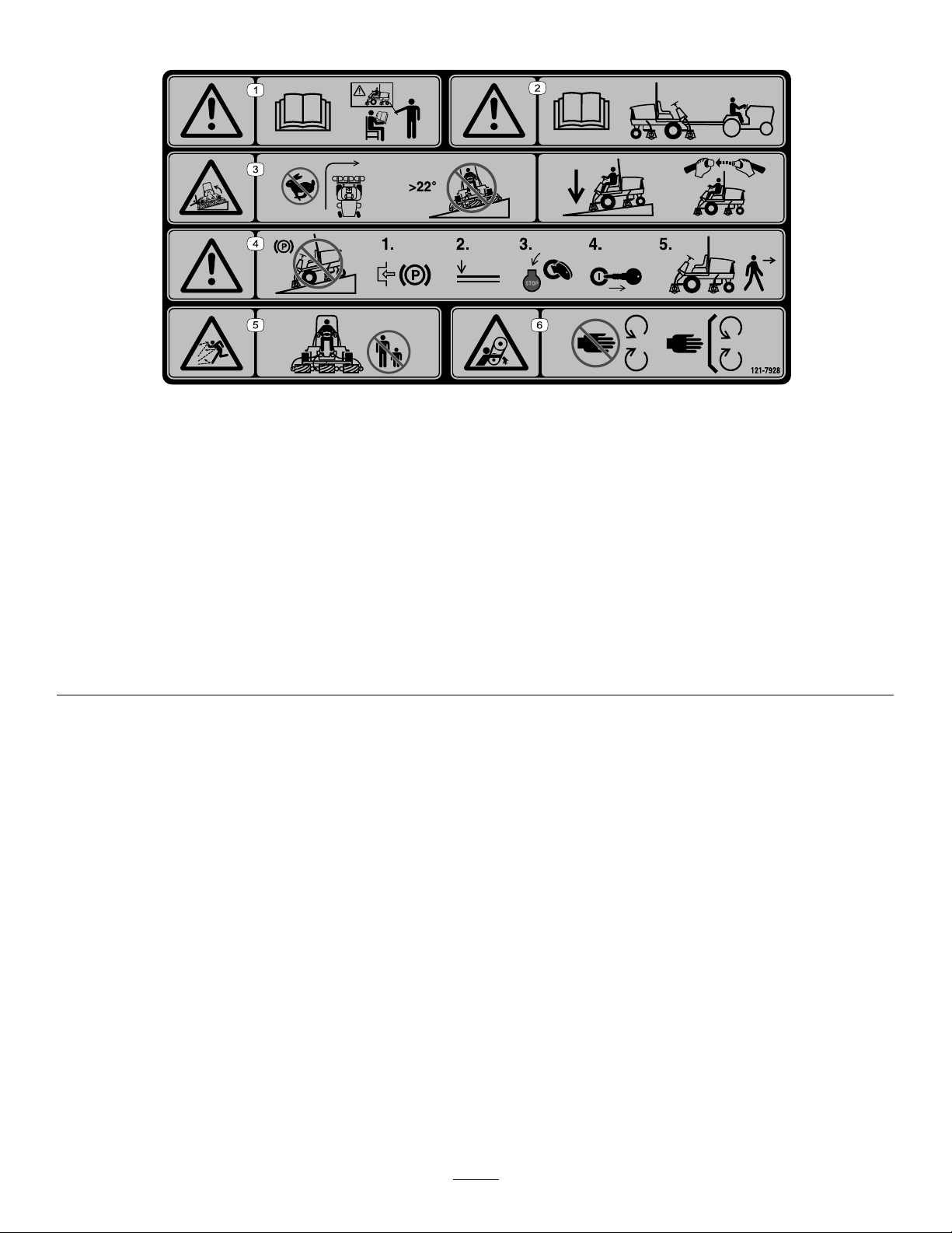
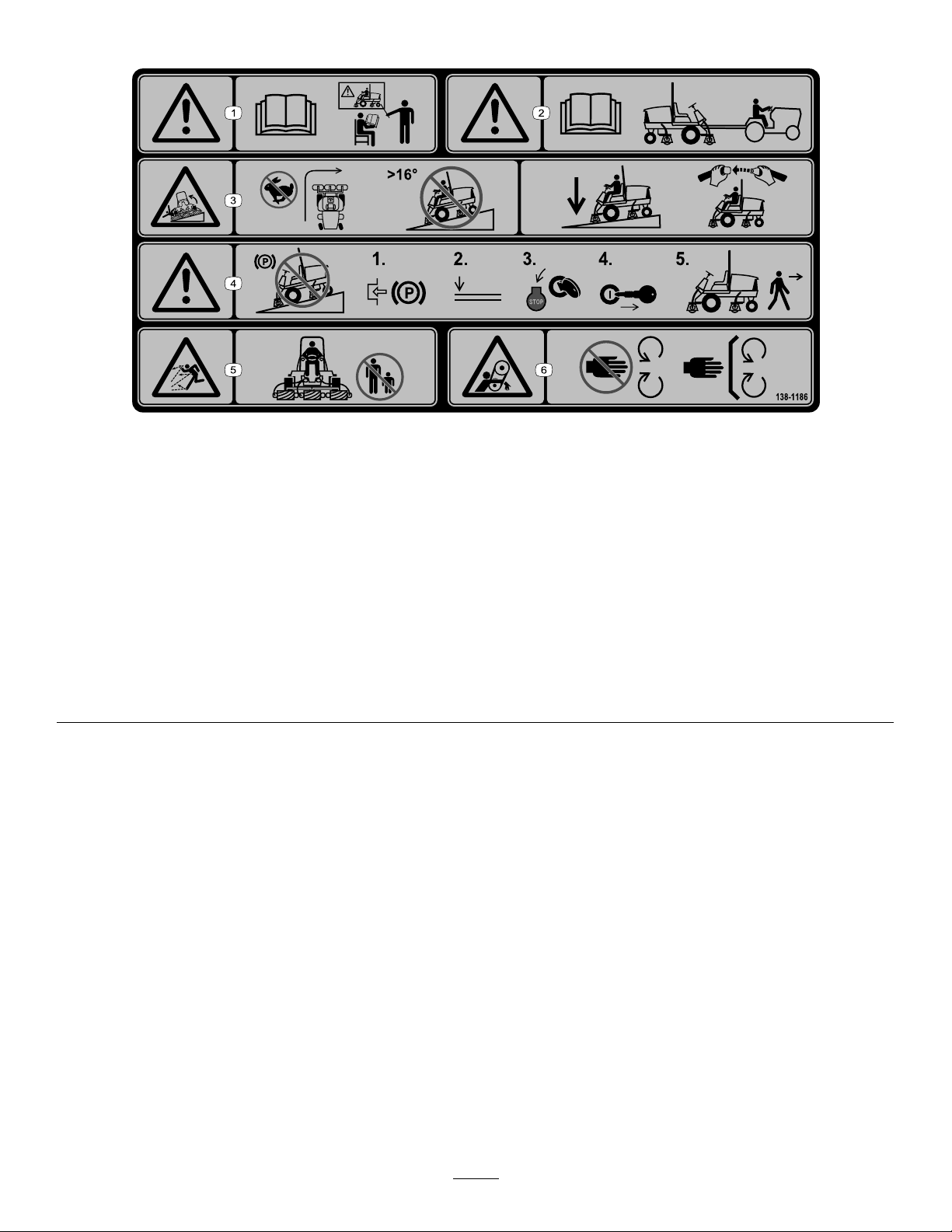
SafetyandInstructionalDecals..........................5
Setup......................................................................13
1InstallingtheCuttingUnits..............................14
2AdjustingtheTurfCompensation
Spring...........................................................16
3InstallingtheCEDecals.................................17
4InstallingtheHoodLatch(CEOnly)................17
5ReducingtheTirePressure............................18
6UsingtheCutting-UnitKickstand....................18
ProductOverview...................................................19
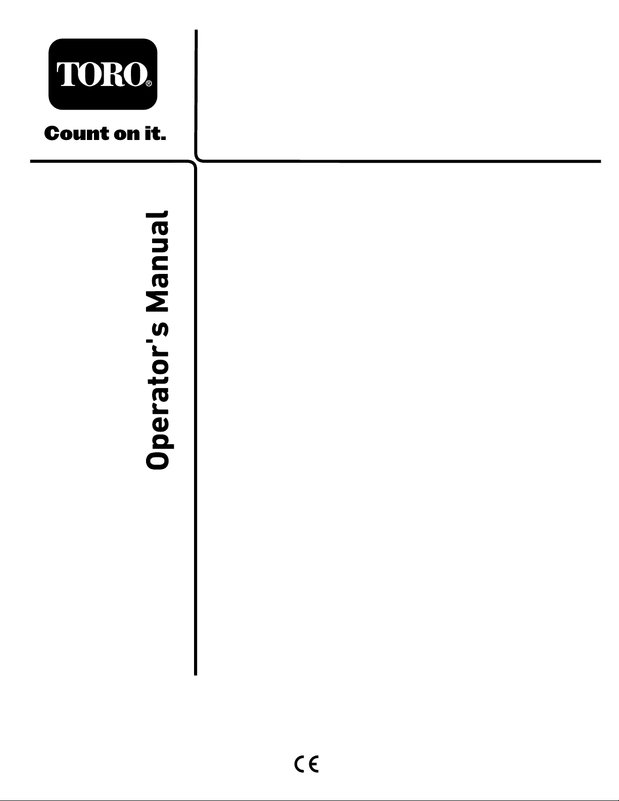
Controls...........................................................19
Specications..................................................23
Attachments/Accessories.................................23
BeforeOperation.................................................24
BeforeOperationSafety...................................24
PerformingDailyMaintenance..........................24
FillingtheFuelTank..........................................24
AdjustingtheSeat............................................25
DuringOperation.................................................26
DuringOperationSafety...................................26
StartingtheEngine...........................................27
ShuttingOfftheEngine.....................................27
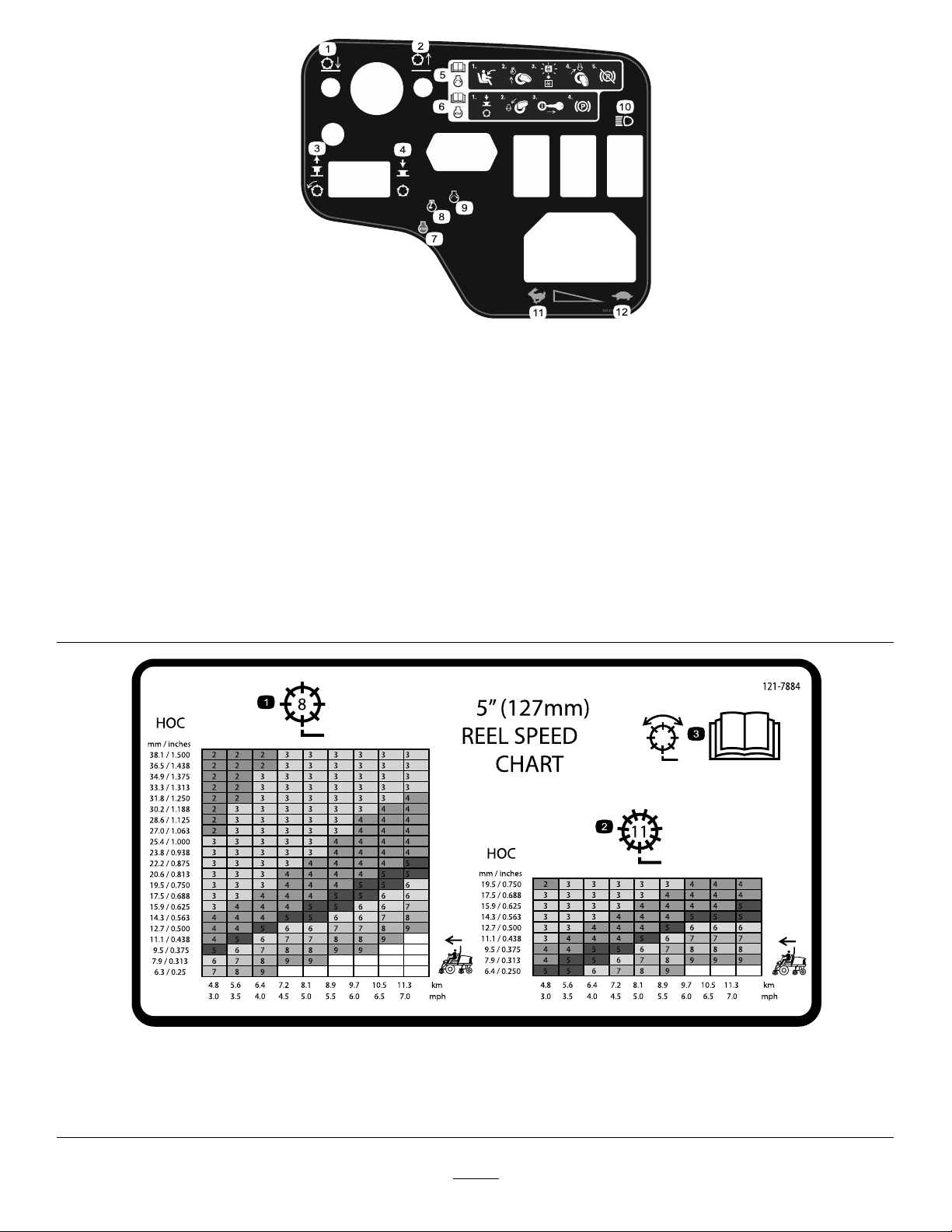
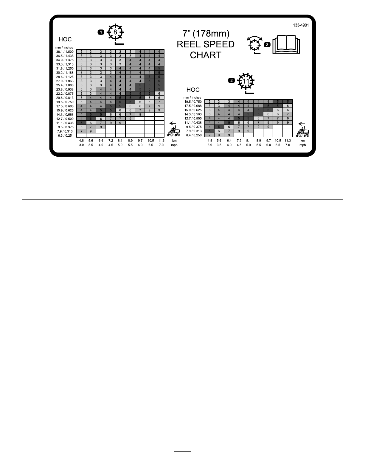
SettingtheReelSpeed.....................................27
AdjustingtheLift-ArmCounterbalance.............29
BleedingtheFuelSystem.................................29
UnderstandingtheDiagnosticLight..................30
UnderstandingtheDiagnosticACE
Display..........................................................30
CheckingtheInterlockSwitches.......................30
OperatingTips.................................................32
AfterOperation....................................................33
AfterOperationSafety......................................33
PushingorTowingtheMachine........................33
HaulingtheMachine.........................................34
IdentifyingtheTie-DownPoints........................35
Maintenance...........................................................36
MaintenanceSafety..........................................36
RecommendedMaintenanceSchedule(s)...........36
DailyMaintenanceChecklist.............................38
Pre-MaintenanceProcedures..............................39
RemovingtheHood..........................................39
RemovingtheBatteryCover.............................39
Lubrication..........................................................40
GreasingtheBearingsandBushings................40
EngineMaintenance...........................................41
EngineSafety...................................................41
CheckingtheEngine-OilLevel..........................41
ServicingtheAirCleaner..................................42
ChangingtheEngineOilandFilter....................43
FuelSystemMaintenance...................................43
ServicingtheFuelT ank.....................................43
InspectingtheFuelLinesand
Connections..................................................43
DrainingtheWaterSeparator...........................44
ChangingtheFuelFilterCanister......................44
BleedingAirfromtheInjectors..........................44
ElectricalSystemMaintenance...........................45
ElectricalSystemSafety...................................45
ServicingtheBattery.........................................45
CheckingtheFuses..........................................45
DriveSystemMaintenance..................................46
CheckingtheTirePressure...............................46
TorquingtheWheelNuts...................................46
AdjustingtheTractionDriveforNeutral.............46
CoolingSystemMaintenance..............................47
CoolingSystemSafety.....................................47
CheckingtheCoolingSystem...........................47
CleaningtheEngineCoolingSystem................48
BrakeMaintenance.............................................48
AdjustingtheParkingBrake..............................48
BeltMaintenance................................................49
ServicingtheEngineBelts................................49
ControlsSystemMaintenance.............................50
AdjustingtheThrottle........................................50
HydraulicSystemMaintenance...........................50
HydraulicSystemSafety...................................50
CheckingtheHydraulicLinesand
Hoses............................................................50
CheckingtheHydraulicFluid............................50
HydraulicFluidSpecications...........................51
HydraulicFluidCapacity...................................51
ChangingtheHydraulicFluid............................52
ChangingtheHydraulicFilter............................52
CuttingUnitSystemMaintenance........................53
BladeSafety.....................................................53
CheckingtheReel-to-BedknifeContact............53
UsingtheOptionalGaugeBar..........................54
BacklappingtheCuttingUnits...........................54
Cleaning..............................................................55
WashingtheMachine.......................................55
Storage...................................................................56
StorageSafety..................................................56
PreparingtheTractionUnit...............................56
PreparingtheEngine........................................56
3

Safety
Thismachinehasbeendesignedinaccordance
withENISO5395(whenyoucompletethesetup
procedures)andANSIB71.4-2017.
GeneralSafety
Thisproductiscapableofamputatinghandsandfeet
andofthrowingobjects.
•Readandunderstandthecontentsofthis
Operator’sManualbeforestartingtheengine.
•Useyourfullattentionwhileoperatingthe
machine.Donotengageinanyactivitythat
causesdistractions;otherwise,injuryorproperty
damagemayoccur.
•Donotputyourhandsorfeetnearmoving
componentsofthemachine.
•Donotoperatethemachinewithoutallguards
andothersafetyprotectivedevicesinplaceand
functioningproperlyonthemachine.
•Keepbystandersandchildrenoutoftheoperating
area.Neverallowchildrentooperatethemachine.
•Shutofftheengine,removethekey,andwait
forallmovementtostopbeforeyouleavethe
operator’sposition.Allowthemachinetocool
beforeadjusting,servicing,cleaning,orstoringit.
Improperlyusingormaintainingthismachinecan
resultininjury.Toreducethepotentialforinjury,
complywiththesesafetyinstructionsandalways
payattentiontothesafety-alertsymbol,which
meansCaution,Warning,orDanger—personalsafety
instruction.Failuretocomplywiththeseinstructions
mayresultinpersonalinjuryordeath.
Engine-Emission
Certication
TheengineinthismachineisEPATier4FinalandEU
StageVemissionscompliant.
4

SafetyandInstructionalDecals
Safetydecalsandinstructionsareeasilyvisibletotheoperatorandarelocatednearanyarea
ofpotentialdanger.Replaceanydecalthatisdamagedormissing.
decal133-8062
133-8062
decal93-7276
93-7276
1.Explosionhazard—weareyeprotection.
2.Causticliquid/chemicalburnhazard—toperformrstaid,
ushwithwater.
3.Firehazard—nore,openames,orsmoking.
4.Poisonhazard—keepchildrenawayfromthebattery.
99-3444
decal99-3444
99-3444
1.Transportspeed—fast2.Mowingspeed—slow
decal106-6755
106-6755
1.Enginecoolantunder
pressure.
3.Warning—donottouchthe
hotsurface.
2.Explosionhazard—read
theOperator'sManual.
4.Warning—readthe
Operator'sManual.
decal110-9642
110-9642
1.Storedenergyhazard—readtheOperator'sManual.
2.Movethecotterpintotheholeclosesttotherodbracket
andthenremovetheliftarmandpivotyoke.
decal117-3270
117-3270
1.Warning—donottouchthehotsurface.
2.Cutting/dismembermenthazard,hand;entanglement
hazard,belt—stayawayfrommovingparts,keepallguards
andshieldsinplace.
decal120-0627
120-0627
1.Cutting/dismembermenthazard,fan—stayawayfrom
movingparts,keepallguardsandshieldsinplace.
5

decal120-1683
120-1683
1.Warning—readtheOperator'sManual;alloperatorsshould
betrainedbeforeoperatingthemachine.
4.Warning—donotparkthemachineonslopes;engagethe
parkingbrake,lowerthecuttingunits,shutofftheengine,and
removethekeybeforeleavingthemachine.
2.Warning—readtheOperator'sManualbeforetowingthe
machine.
5.Thrownobjecthazard—keepbystandersaway.
3.Tippinghazard—driveslowlywhenturning;donotturnsharply
whiletravelingfast;lowerthecuttingunitswhendrivingdown
slopes;usearolloverprotectionsystemandweartheseatbelt.
6.Entanglementhazard,belt—stayawayfrommovingparts;
keepallguardsandshieldsinplace.
6

decal120-2105
120-2105
1.Lowerthecuttingunits.5.ReadtheOperator’sManualfor
informationonstartingtheengine—sit
intheoperator’sposition,turnthekey
totheenginepreheatposition,wait
untiltheenginepreheatlightturnsoff,
turnthekeytotheenginestartposition,
anddisengagetheparkingbrake.
9.Engine—Start
2.Raisethecuttingunits.6.ReadtheOperator’sManual
forinformationonstoppingthe
engine—disengagethecuttingunits,
turnthekeytotheenginestopposition,
removethekeyfromtheignition,and
engagetheparkingbrake.
10.Lights
3.Pulluptoengagethecuttingunits.7.Engine—Shutoff11.Fast
4.Pushdowntodisengagethecutting
units.
8.Engine—Preheat12.Slow
decal121-7884
121–7884
1.8bladereeladjustment3.ReadtheOperator’sManualforinformationonadjustingthe
reel.
2.11bladereeladjustment
7

decal133-4901
133-4901
1.8-bladereeladjustment3.ReadtheOperator’sManualforinformationonadjustingthe
reel.
2.11-bladereeladjustment
8

Model03910
decal121-7928
121-7928
Note:Thismachinecomplieswiththeindustrystandardstabilitytestinthestaticlateralandlongitudinaltestswiththemaximum
recommendedslopeindicatedonthedecal.ReviewtheinstructionsforoperatingthemachineonslopesintheOperator’sManualas
wellastheconditionsinwhichyouwouldoperatethemachinetodeterminewhetheryoucanoperatethemachineintheconditions
onthatdayandatthatsite.Changesintheterraincanresultinachangeinslopeoperationforthemachine.Ifpossible,keepthe
cuttingunitsloweredtothegroundwhileoperatingthemachineonslopes.Raisingthecuttingunitswhileoperatingonslopescan
causethemachinetobecomeunstable.
1.Warning—readtheOperator'sManual;alloperatorsshould
betrainedbeforeoperatingthemachine.
4.Warning—donotparkthemachineonslopes;engagethe
parkingbrake,lowerthecuttingunits,shutofftheengine,and
removethekeybeforeleavingthemachine.
2.Warning—readtheOperator'sManualbeforetowingthe
machine.
5.Thrownobjecthazard—keepbystandersaway.
3.Tippinghazard—donotturnsharplywhiletravelingfast;do
notdriveupordownslopesgreaterthan22°;lowerthecutting
unitswhendrivingdownslopes;usearolloverprotection
systemandweartheseatbelt.
6.Entanglementhazard,belt—stayawayfrommovingparts;
keepallguardsandshieldsinplace.
9

Models03820and03821AfxoverPartNo.120-1683forCE
decal138-1186
138-1186
Note:Thismachinecomplieswiththeindustrystandardstabilitytestinthestaticlateralandlongitudinaltestswiththemaximum
recommendedslopeindicatedonthedecal.ReviewtheinstructionsforoperatingthemachineonslopesintheOperator’sManualas
wellastheconditionsinwhichyouwouldoperatethemachinetodeterminewhetheryoucanoperatethemachineintheconditions
onthatdayandatthatsite.Changesintheterraincanresultinachangeinslopeoperationforthemachine.Ifpossible,keepthe
cuttingunitsloweredtothegroundwhileoperatingthemachineonslopes.Raisingthecuttingunitswhileoperatingonslopescan
causethemachinetobecomeunstable.
1.Warning—readtheOperator'sManual;alloperatorsshould
betrainedbeforeoperatingthemachine.
4.Warning—donotparkthemachineonslopes;engagethe
parkingbrake,lowerthecuttingunits,shutofftheengine,and
removethekeybeforeleavingthemachine.
2.Warning—readtheOperator'sManualbeforetowingthe
machine.
5.Thrownobjecthazard—keepbystandersaway.
3.Tippinghazard—donotturnsharplywhiletravelingfast;do
notdriveupordownslopesgreaterthan16°;lowerthecutting
unitswhendrivingdownslopes;usearolloverprotection
systemandweartheseatbelt.
6.Entanglementhazard,belt—stayawayfrommovingparts;
keepallguardsandshieldsinplace.
10

Model03910
decal138-6980
138-6980
1.ReadtheOperator’sManual.
Models03820and03821
decal138-6981
138-6981
1.ReadtheOperator’sManual.
11

decalbatterysymbols
BatterySymbols
Someorallofthesesymbolsareonyourbattery.
1.Explosionhazard6.Keepbystandersaway
fromthebattery.
2.Nore,opename,or
smoking
7.Weareyeprotection;
explosivegasescan
causeblindnessandother
injuries.
3.Causticliquid/chemical
burnhazard
8.Batteryacidcancause
blindnessorsevereburns.
4.Weareyeprotection.9.Flusheyesimmediately
withwaterandgetmedical
helpfast.
5.ReadtheOperator's
Manual.
10.Containslead;donot
discard
12

Setup
LooseParts
Usethechartbelowtoverifythatallpartshavebeenshipped.
ProcedureDescriptionQty.Use
Righthoseguide1
1Lefthoseguide1Installthecuttingunits.
2Nopartsrequired–Adjusttheturfcompensationspring.
Warningdecal121-7928(machine
model03910)1
Warningdecal138-1186(machine
models03820and03821)1
CEdecal1
3
Productionyeardecal1
InstalltheCEdecals,ifrequired.
Lockbracket1
Rivet2
Washer1
Screw(1/4x2inches)1
4
Locknut(1/4inch)1
Installthehoodlatch(CEonly).
5Nopartsrequired–Reducethetirepressure.
6Cutting-unitkickstand1Usethecutting-unitkickstand.
MediaandAdditionalParts
DescriptionQty.Use
Keys2Starttheengine.
Operator'sManual1
Engineowner’smanual1Readthemanualsbeforeoperatingthemachine.
Cuttingperformancepaper1Usethepaperforadjustingthecuttingunitreel-to-bedknife
contact.
Shim1Usetheshimforadjustingthecuttingunitreel-to-bedknife
contact.
Note:Determinetheleftandrightsidesofthemachinefromthenormaloperatingposition.
13

1
InstallingtheCuttingUnits
Partsneededforthisprocedure:
1Righthoseguide
1Lefthoseguide
Procedure
1.Parkthemachineonalevelsurface,engagethe
parkingbrake,shutofftheengine,andremove
thekeyfromtheignitionswitch.
2.Removethereelmotorsfromtheshipping
brackets.
3.Removeanddiscardtheshippingbrackets.
4.Removethecuttingunitsfromthecartons.
Assembleandadjustthemasdescribedinthe
cuttingunitOperator'sManual.
5.Makesurethatthecounterweight(Figure3)is
installedtotheproperendofthecuttingunitas
describedinthecuttingunitOperator'sManual.
g019938
Figure3
1.Counterweight
6.Allthecuttingunitsareshippedwiththeturf
compensationspringmountedtotheright
sideofthecuttingunit.Ensurethattheturf
compensationspringismountedtothesame
sideofthecuttingunitasthereeldrivemotor.
Positiontheturfcompensationasfollows:
A.Removethe2carriageboltsandnuts
securingtherodbrackettothecuttingunit
tabs(Figure4).
g003949
Figure4
1.Turfcompensationspring3.Springtube
2.Rodbracket
B.Removetheangenutsecuringthespring
tubebolttothecarrierframetab(Figure4),
andremovetheassembly.
C.Mountthespringtubebolttotheopposite
tabonthecarrierframeandsecureitwith
theangenut.
Note:Positiontheboltheadtotheouter
sideofthetabasshowninFigure4.
g003967
Figure5
1.Oppositecarrierframetab2.Rodbracket
D.Mounttherodbrackettothecuttingunit
tabswiththecarriageboltsandnuts(Figure
5).
Note:Wheninstallingorremovingthecutting
units,makesurethatthehairpincotteris
installedinthespringrodholenexttotherod
bracket.Otherwise,installthehairpincotterin
theholeintheendoftherod.
7.Oncuttingunit4(leftfront)andcuttingunit5
(rightfront),usetherod-bracketmountingnuts
toinstallthehoseguidestothefrontofthe
cutting-unittabs.Thehoseguidesshouldlean
towardthecentercuttingunit(Figure6,Figure
7,Figure8).
14

g031275
Figure6
1.Cuttingunit15.Cuttingunit5
2.Cuttingunit26.Reelmotor
3.Cuttingunit37.Weight
4.Cuttingunit4
g015160
Figure7
1.Hoseguide(leftside
shown)
3.Nuts
2.Rodbracket
g289454
Figure8
1.Hoseguides(eachmustleantowardthecentercuttingunit)
8.Loweralltheliftarmscompletely.
9.Removethesnapperpinandthecapfromthe
lift-armpivotyoke(Figure9).
g003975
Figure9
1.Snapperpin2.Cap
10.Forthefrontcuttingunits,slideacuttingunit
undertheliftarmwhileinsertingthecarrierframe
shaftupintothelift-armpivotyoke(Figure10).
g020321
Figure10
1.Liftarm3.Lift-armpivotyoke
2.Carrierframeshaft
11.Usethefollowingprocedureontherearcutting
unitswhentheheightofcutisabove1.2cm
(3/4inch).
A.Removethelynchpinandwashersecuring
thelift-armpivotshafttotheliftarmand
slidethelift-armpivotshaftoutofthelift
arm(Figure11).
15

g003979
Figure11
1.Lift-armshaftlynchpinandwasher
B.Insertthelift-armyokeontothecarrier
frameshaft(Figure10).
C.Insertthelift-armshaftintotheliftarmand
secureitwiththewasherandlynchpin
(Figure11).
12.Insertthecapoverthecarrierframeshaftand
lift-armyoke.
13.Securethecapandthecarrierframeshafttothe
lift-armyokewiththesnapperpin.
Note:Usetheslotifasteeringcuttingunitis
desiredorusetheholeifthecuttingunitistobe
lockedinposition(Figure9).
14.Securethelift-armchaintothechainbracket
withthesnapperpin(Figure12).
Note:Usethenumberofchainlinksspecied
inthecuttingunitOperator'sManual.
g003948
Figure12
1.Lift-armchain3.Snapperpin
2.Chainbracket
15.Coatthesplineshaftofthereelmotorwithclean
grease.
16.Oilthereel-motorO-ringandinstallitontothe
motorange.
17.Installthemotorbyrotatingitclockwisesothat
themotorangesclearthelocknuts(Figure
13).Rotatethemotorcounterclockwiseuntilthe
angesencirclethenuts,thentightenthenuts.
Important:Makesurethatthereelmotor
hosesarenottwisted,kinked,oratriskof
beingpinched.
g020322
Figure13
1.Reel-drivemotor2.Mountingnuts
2
AdjustingtheTurf
CompensationSpring
NoPartsRequired
Procedure
Theturfcompensationspring(Figure14)transfers
weightfromthefronttotherearroller.Thishelps
toreduceawavepatternintheturf,alsoknownas
marcellingorbobbing.
Important:Makespringadjustmentswiththe
cuttingunitmountedtothetractionunit,pointing
straightaheadandloweredtotheshopoor.
1.Makesurethatthehairpincotterisinstalledin
therearholeinthespringrod(Figure14).
16

g020164
Figure14
1.Turfcompensationspring3.Springrod
2.Hairpincotter4.Hexnuts
2.Tightenthehexnutsonthefrontendofthe
springroduntilthecompressedlengthofthe
spring(Figure14)is12.7cm(5inches)for
5-inchcuttingunitsand15.8cm(6-1/4inches)
for7-inchcuttingunits.
Note:Whenoperatingonroughterrain,
decreasethespringlengthby2.5cm(1/2inch).
Groundfollowingwillbeslightlydecreased.
3
InstallingtheCEDecals
Partsneededforthisprocedure:
1Warningdecal121-7928(machinemodel03910)
1Warningdecal138-1186(machinemodels03820and
03821)
1CEdecal
1Productionyeardecal
Procedure
OnmachinesrequiringCEcompliance,applythe
productionyeardecal(PartNo.133-5615)nearthe
serialplate,theCEdecal(PartNo.93-7252)near
thehoodlock,andtheCEwarningdecal(PartNo.
121-7928formachinemodel03910andPartNo.
138-1186formachinemodels03820and03821)over
thestandardwarningdecal(PartNo.120-1683).
4
InstallingtheHoodLatch
(CEOnly)
Partsneededforthisprocedure:
1Lockbracket
2Rivet
1Washer
1Screw(1/4x2inches)
1Locknut(1/4inch)
Procedure
1.Unhookthehoodlatchfromthehood-latch
bracket.
2.Removethe2rivetssecuringthehood-latch
brackettothehood(Figure15)andremovethe
hood-latchbracketfromthehood.
g012628
Figure15
1.Hood-latchbracket2.Rivets
3.Whilealigningthemountingholes,positionthe
CElockbracketandthehood-latchbracketonto
thehood.
Note:Thelockbracketmustbeagainstthe
hood(Figure16).Donotremovetheboltand
nutfromthelock-bracketarm.
17

g012629
Figure16
1.CElockbracket2.Boltandnut
4.Alignthewasherswiththeholesontheinsideof
thehood.
5.Rivetthebracketsandthewasherstothehood
(Figure16).
6.Hookthelatchontothehood-latchbracket
(Figure17).
g012630
Figure17
1.Hoodlatch
7.Screwtheboltintotheotherarmofthehood-lock
brackettolockthelatchinposition(Figure18).
Note:Tightentheboltsecurelybutdonot
tightenthenut.
g012631
Figure18
1.Bolt3.Armofhood-lockbracket
2.Nut
5
ReducingtheTirePressure
NoPartsRequired
Procedure
Thetiresareoverinatedatthefactoryforshipping
purposes.Reducethepressuretotheproperlevels
beforestartingthemachine;refertoCheckingtheTire
Pressure(page46).
6
UsingtheCutting-Unit
Kickstand
Partsneededforthisprocedure:
1Cutting-unitkickstand
Procedure
Wheneveryoutipacuttingunittoexposethe
bedknife/reel,propuptherearofthecuttingunitwith
thekickstandtoensurethatthenutsonthebackend
ofthebedbaradjustingscrewsarenotrestingonthe
worksurface(Figure19).
18

g020158
Figure19
1.Cutting-unitkickstand
Securethekickstandtothechainbracketwiththe
snapperpin(Figure20).
g004144
Figure20
1.Chainbracket3.Cutting-unitkickstand
2.Snapperpin
ProductOverview
g216864
Figure21
1.Enginehood5.Seatadjustmentlever
2.Seat6.Frontcuttingunits
3.Controlarm7.Rearcuttingunits
4.Steeringwheel
Controls
g020079
Figure22
1.Forwardtractionpedal3.Mow/transportslide
2.Reversetractionpedal4.Tilt-steeringlever
TractionPedals
Presstheforwardtractionpedal(Figure22)tomove
forward.Pressreversetractionpedal(Figure22)to
movebackwardortoassistinstoppingwhenmoving
forward.Also,allowthepedaltomoveormoveitto
theNEUTRALpositiontostopthemachine.
19

Mow/TransportSlide
Usingyourheel,movethemow/transportslide(Figure
22)tothelefttotransportandtotherighttomow.The
cuttingunitswillonlyoperateintheMOWposition
andnotlowerintheTRANSPORTposition.
Important:Themowspeedissetatthefactoryto
9.7km/h(6mph).Itcanbeincreasedordecreased
byadjustingthespeedstopscrew(Figure23).
g008888
Figure23
1.Speedstopscrew
Tilt-SteeringLever
Pullthetilt-steeringlever(Figure22)backtotiltthe
steeringwheeltothedesiredposition.Thenpushthe
leverforwardtosecuretheposition.
IgnitionSwitch
Theignitionswitch(Figure24),usedtostart,shut
off,andpreheattheengine,has3positions:OFF,
ON/PREHEAT,andSTART.Rotatethekeytothe
ON/PREHEATpositionuntiltheglow-plugindicator
lightgoesout(approximately7seconds);thenrotate
thekeytotheSTARTpositiontoengagethestarter
motor.Releasethekeywhentheenginestarts.The
keymovesautomaticallytotheON/RUNposition.To
shutofftheengine,rotatethekeytotheOFFposition.
Removethekeyfromtheswitchtopreventaccidental
starting.
g019980
Figure24
1.Parkingbrake7.Oil-pressurelight
2.Ignitionswitch8.Temperaturelight
3.Enable/Disableswitch9.Lightswitch
4.Diagnosticlight10.Glow-plugindicatorlight
5.Lowermow/raisecontrol
lever
11.Throttle
6.Hourmeter12.Alternatorlight
Throttle
Movethethrottle(Figure24)forwardtoincreasethe
enginespeedandrearwardtodecreasetheengine
speed.
Enable/DisableSwitch
Usetheenable/disableswitch(Figure24)in
conjunctionwiththelowermow/raisecontrollever
tooperatethecuttingunits.Youcannotlowerthe
cuttingunitswhenthemow/transportleverisin
theTRANSPORTposition.
HourMeter
Thehourmeter(Figure24)indicatesthetotalhours
ofmachineoperation.Itstartstofunctionwhenever
thekeyswitchison.
LowerMow/RaiseControlLever
Thislever(Figure24)raisesandlowersthecutting
unitsandalsostartsandstopsthereelswhenthe
reelsareenabledinthemowmode.Youcannot
lowerthecuttingunitswhenthemow/transport
leverisintheTRANSPORTposition.
Note:Whenthecuttingunitsareenabled,youdonot
needtoholdtheleverintheforwardpositionwhilethe
cuttingunitsareloweredorraised.
20
Other manuals for Reelmaster 3555
3
This manual suits for next models
5
Table of contents
Other Toro Lawn Mower manuals

Toro
Toro Groundsmaster 4000-D User manual

Toro
Toro Wheel Horse 78350 User manual

Toro
Toro 22176TE User manual

Toro
Toro 74262TE User manual

Toro
Toro 652D User manual

Toro
Toro 20955 User manual

Toro
Toro GreensPro 1260 User manual

Toro
Toro 21025 User manual

Toro
Toro Greensmaster 3250-D User manual

Toro
Toro 74176 User manual