Toro 30821 User manual

OPERATOR'S
MANUAL
FORM NO. 3325-238 Rev A
MODEL NO. 30821—200000001 & UP
GROUNDSMASTER®3500-D
®
© The TORO COMPANY—2000

SAFETY INSTRUCTIONS 3
SYMBOLS 6
SPECIFICATIONS 9
PRE-OPERATING CHECKS 10
Adjust Lift Arms 10
Check Crankcase Oil 11
Fill The fuel Tank 11
Check Cooling S stem 12
Check H draulic S stem Fluid 12
Check Tire Pressure 14
Check Torque Of Wheel Nuts 14
CONTROLS 15
OPERATING INSTRUCTIONS 17
Starting/Stopping The engine 17
Bleeding The fuel S stem 17
Check Operation of Interlock Switches 18
Towing The traction Unit 18
Operating Characteristics 19
Mowing Techniques 20
After Mowing 20
DAILY MAINTENANCE CHECKLIST 21
MAINTENANCE SCHEDULE 21
LUBRICATION 22
Hood Removal 24
AIR CLEANER MAINTENANCE 24
General Air Cleaner Maintenance 24
Servicing The air Cleaner 24
ENGINE MAINTENANCE 25
Engine Oil and Filter 25
Fuel S stem 25
Bleeding Air From Injectors 26
Engine Cooling S stem 27
Servicing Engine Belts 27
Adjusting The throttle 28
HYDRAULIC MAINTENANCE 29
Changing H draulic Fluid 29
Replacing H draulic Filter 29
Checking H draulic Lines and Hoses 30
Adjusting The traction Drive For Neutral 30
BRAKE MAINTENANCE 30
Parking Brake Adjustment 30
ELECTRICAL MAINTENANCE 31
Batter Care 31
Batter Storage 32
Fuses 32
PREPARATION FOR SEASONAL STORAGE 33
IDENTIFICATION AND ORDERING 33
– 2 –
The Groundsmaster 3500-D was developed to provide an efficient, reliable and time-saving method of
mowing high-quality turf. The latest concepts in engineering and design have been incorporated into this
machine along with the highest quality parts and workmanship. Excellent service will be derived if proper
operation and maintenance practices are followed.
Safety, mechanical and some general information in this manual is emphasized. DANGER, WARNING and
CAUTION identify safety messages. Whenever the triangular safety alert symbol appears, it is followed by
a safety message that must be read and understood. For more complete details concerning safety, read the
safety instructions on pages 3–5. IMPORTANT identifies special mechanical information and NOTE
identifies general information worthy of special attention.
Whenever yo have questions or need service, contact your local authorized Toro Distributor. Besides having
a complete line of accessories and professional turf care service technicians, the distributor has a complete
line of genuine TORO replacement parts to keep your machine operating properly. Keep your TORO
product all TORO. Buy genuine TORO parts and accessories.
Table of Contents
Foreword

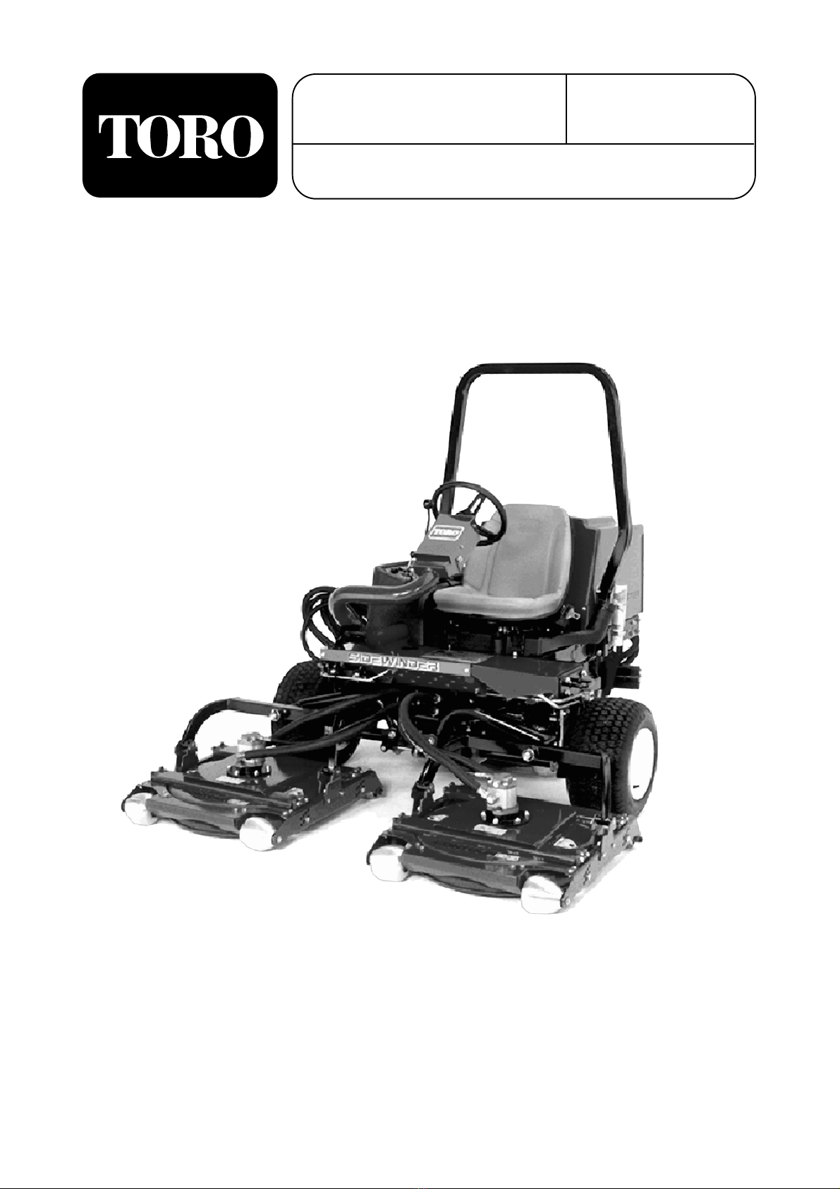
The Groundsmaster 3500-D was tested and certified
by TORO for compliance with the B71.4-1999
specifications of the American National Standards
Institute. Although hazard control and accident
prevention partially are dependent upon the design
and configuration of the machine, these factors are
also dependent upon the awareness, concern, and
proper training of the personnel involved in the
operation, transport, maintenance, and storage of
the machine. Improper use or maintenance by the
operator or owner of the machine can result in
injury. To reduce the potential for any injury,
comply with the following safety instructions.
Supervisor’s Responsibilities
1. Make sure operators are thoroughly trained and
familiar with the operator’s manual and all the
labels on the machine.
2. Be sure to establish your own special
procedures and work rules for unusual
operating conditions (e.g., slopes too steep for
machine operation. Survey the complete
mowing site to determine the hills on which the
machine can be safely operated. When
performing this site survey, always use
common sense and take into consideration the
turf condition and the rollover risk.
To determine which hills or slopes on which the
machine may be safely operated, use the
inclinometer provided with each machine. To
perform a site survey, lay a 1.25 meter board on
the slope surface and measure the angle of the
slope. The board will average the slope but will
not take into consideration dips or holes. THE
MAXIMUM SIDE HILL ANGLE SHOULD
NOT BE GREATER THAN 25 DEGREES.
Before Operating
3. Operate the machine only after reading and
understanding the contents of this manual and
viewing the operator’s training video supplied
with the machine. A free replacement manual is
available by sending complete model and serial
number to:
The Toro Company
8111 Lyndale Ave. S.
Bloomington, MN 55420-1196.
4. Only trained operators, skilled in slope
operation and who have read this manual and
viewed the operator’s training video should
operate the machine. Never allow children to
operate the machine or adults to operate it
without proper instructions.
5. Become familiar with the controls and know
how to stop the machine and engine quickly.
6. Do not carry passengers on the machine. Keep
everyone, especially children and pets, away
from the areas of operation.
7. Keep all shields, safety devices and decals in
place. If a shield, safety device or decal is
damaged, malfunctioning or illegible, repair or
replace it before operating the machine.
8. Always wear substantial shoes. Do not operate
machine while wearing sandals, tennis shoes or
sneakers. Do not wear loose fitting clothing
because it could get caught in moving parts and
possibly cause personal injury.
9. Wearing safety glasses, safety shoes, long pants
and a helmet is advisable and required by some
local ordinances and insurance regulations.
10. Make sure the work area is clear of objects
which might be picked up and thrown by the
blades.
11. Fill fuel tank with diesel fuel before starting
engine. Avoid spilling any fuel. Since fuel is
highly flammable, handle it carefully.
A. Use an approved fuel container.
B. Do not remove cap from fuel tank when
engine is hot or running.
C. Do not smoke while handling diesel fuel.
D. Fill fuel tank outdoors and not over one
inch from the top of the tank, (bottom of
the filler neck). Do not overfill.
– 3 –
Safety

While Operating
12. Always wear your seat belt.
13. Do not run the engine in a confined area
without adequate ventilation. Exhaust fumes are
hazardous and could be deadly.
14. Sit on the seat when starting and operating the
machine.
15. Check interlock switches daily for proper
operation (Refer To Checking Interlock
Switches). Do not rely entirely on safety
switches -shut off engine before getting off
seat. If a switch fails, replace it before
operating the machine. The interlock system is
for your protection, so do not bypass it.
Replace all interlock switches every two years.
16. The operator must be skilled and trained in how
to drive on hillsides. Failure to use caution on
slopes or hills may cause vehicle to tip or roll,
possibly resulting in personal injury or death.
17. This triplex mower has a unique drive system
for superior traction on hills. The uphill wheel
will not spin out and limit traction like
conventional triplexes. If operated on a side hill
that is too steep, rollover may occur before
losing traction.
18. Before backing up, look to the rear and assure
no one is behind the machine. Watch out for
traffic when near or crossing roads. Always
yield the right of way.
19. Keep hands, feet and clothing away from
moving parts and the mower discharge area.
20. The slope angle at which the machine will tip is
dependent on many factors. Among these are
mowing conditions such as wet or undulating
turf, speed (especially in turns), position of the
cutting units (with sidewinder), tire pressure
and operator experience. At side hill slope
angles of 20 degrees or less the risk of a
rollover is low. As the slope angle increases to a
Toro recommended maximum limit of 25
degrees the risk of a rollover increases to a
moderate level. DO NOT EXCEED A 25
DEGREE SIDE HILL ANGLE BECAUSE
THE RISK OF A ROLLOVER AND SERIOUS
INJURY OR DEATH IS VERY HIGH. The
Groundsmaster 3500-D is equipped with an
angle indicator, mounted on the steering tube,
which indicates the side hill angle the machine
is operating on and identifies the recommended
maximum limit of 25 degrees.
Stay alert for holes in terrain and other hidden
hazards which can cause a sudden change in
side hill angle. Use extreme caution when
operating close to sand traps, ditches, creeks,
steep hillsides or other hazards. Reduce speed
when making sharp turns. Do not turn on hills.
Avoid sudden stops and starts. Use reverse
pedal for braking. Cutting units must be
lowered when going down slopes for steering
control.
21. When starting the engine:
A. Engage parking brake.
B. Be sure traction pedal is in neutral and
blade drive is in disengage position.
C. After engine starts, release parking brake
and keep foot off traction pedal. Machine
must not move. If movement is evident, the
neutral control linkage is incorrectly
adjusted: therefore, shut engine off and
adjust until machine does not move when
traction pedal is released. Refer to
Adjusting Transmission for Neutral.
22. This product may exceed noise levels of 85
dB(A) at the operator position. Ear protectors
are recommended for prolonged exposure to
reduce the potential of permanent hearing
damage.
23. Raise the cutting units when driving from one
work area to another.
24. Do not touch engine, muffler, exhaust pipe or
hydraulic tank while engine is running or soon
after it has stopped because these areas could
be hot enough to cause burns.
25. If a cutting unit strikes a solid object or vibrates
Safety
– 4 –

abnormally, stop immediately. Turn engine off,
wait for all motion to stop and inspect for
damage.
26. Before getting off the seat:
A. Move traction pedal to neutral.
B. Set the parking brake.
C. Disengage the cutting units and wait for the
blades to stop spinning.
D. Stop the engine and remove key from the
ignition switch.
27. Whenever machine is left unattended, make
sure, key is removed from ignition switch and
parking brake is set.
Maintenance
28. Before servicing or making adjustments to the
machine, stop the engine and remove key from
switch to prevent accidental starting of the
engine.
29. Check performance of all interlock switches
daily. Do not defeat interlock system. It is for
your protection. 30. To ensure entire machine is
in good operating condition, frequently check
and keep all nuts, bolts, screws and hydraulic
fittings tight.
31. Make sure all hydraulic line connectors are
tight, and all hydraulic hoses and lines are in
good condition before applying pressure to the
system.
32. Keep body and hands away from pin hole leaks
or nozzles that eject hydraulic fluid under high
pressure. Use paper or cardboard, not hands, to
search for leaks. Hydraulic fluid escaping under
pressure can have sufficient force to penetrate
skin and do serious damage. If fluid is injected
into the skin it must be surgically removed
within a few hours by a doctor familiar with
this form of injury or gangrene may result. 33.
Before disconnecting or performing any work
on the hydraulic system, all pressure in system
must be relieved by stopping engine and
lowering cutting units to the ground.
34. If major repairs are ever needed or if assistance
is desired, contact an Authorized Toro
Distributor.
35. To reduce potential fire hazard, keep the engine
area free of excessive grease, grass, leaves and
accumulation of dirt.
36. If the engine must be running to perform a
maintenance adjustment, keep hands, feet,
clothing, and any other parts of the body away
from the cutting units and any moving parts.
Keep everyone away.
37. Do not overspeed the engine by changing
governor settings. To assure safety and
accuracy, have an Authorized Toro Distributor
check maximum engine speed with a
tachometer.
38. Engine must be shut off before checking oil or
adding oil to the crankcase.
39. To insure optimum performance and safety, use
genuine TORO replacement parts and
accessories. Replacement parts and accessories
made by other manufacturers could be
dangerous, and such use could void the product
warranty of The Toro Company.
Safety
– 5 –

– 6 –
Symbol Glossary
Caustic liquids,
chemical burns to
fingers or hand
Poisonous
fumes or toxic
gases, asphyxiation
Electrical shock,
electrocution High pressure
fluid, injection
into body
High pressure
spray, erosion of
flesh
High pressure
spray, erosion of
flesh
Crushing of
fingers
or hand,
force
applied from
above
Crushing of
toes or foot, force
applied from above
Crushing of
whole body,
applied from
above
Crushing of
torso, force
applied from side
Crushing of fingers
or hand/, force
applied from side
Crushing of
whole body Crushing of
head, torso and
arms
Cutting of
fingers or hand Cutting of footCrushing of leg,
force applied
from side
Severing of
fingers or hand,
mower blade
Severing of
toes or foot,
mower blade
Severing of
toes or fingers,
rotary mower
blade
Cutting or
entanglement of
foot, rotating auger
Severing of
foot, rotating
knives
Severing of
fingers or hand,
impeller blade
Dismember-
ment, front engine
mower in forward
motion
Dismember-
ment, front engine
mower in rearward
motion
Severing of
fingers or hand,
engine fan
Whole body entanglement,
implement input drive line Fingers or
hand entangle-
ment, chain
drive
Hand & arm
entanglement,
belt drive
Thrown or flying
objects, whole
body exposure
Thrown or
flying objects,
face exposure
Thrown or flying
objects, rotary
mover
Runover/back-
over, vehicle Machine
tipping, riding
mower
Machine rollover,
ROPS (rear
engine mower)
Stored energy
hazard, kickback
or upward motion
Hot surfaces,
burns to fingers
or hands
Explosion Fire or open
flame
Secure lifting
cylinder with locking
device before getting
in hazardous area
Do not step on
loading platform
if PTO is connect-
ed to tractor &
engine is running
Do not step Wait until all
machine comp-
onents have
completely
stopped before
touching them
Shut off engine
& remove key
before perform-
ing maintenance
or repair work
Stay a safe
distance from
the machine
Stay clear of
articulation area
while engine is
running
Do not open
or remove safety
shields while
engine is
running
Riding on this
machine is allowed
only on a passen-
ger seat & only if the
driver’s view is not
hindered

Symbol Glossary
– 7 –
Fasten seat
belts Safety alert
triangle Outline safety
alert symbol Read operator’s
manual Fire, open light
and smoking
prohibited
Eye protection
must be worn
Consult technical
manual for proper
service
procedures
Hearing
protection must
be worn
Caution, toxic
risk
Head protection
must be worn Flush with water Engine Transmission Hydraulic systemFirst aid
Oil Coolant (water) Intake air Exhaust gas Pressure Level indicator Liquid level
Brake system
Disengage
Filter Temperature Failure/
Malfunction Start switch/
mechanism On/start Off/stop Engage
Plus/increase/
positive polarity Minus/decrease/
negative polarity Horn Battery charging
condition Hourmeter/
elapsed operating
hours
Fast Slow Continuous
variable, linear
Volume empty Volume full Machine travel
direction,
forward/
rearward
Control lever
operating
direction, dual
direction
Control lever
operating
direction, multiple
direction
Clockwise
rotation Counter-clock-
wise rotation Grease
lubrication
point
Oil lubrication
point Lift point Jack or
support point Draining/
emptying Engine lubricat-
ing oil Engine
lubricating
oil pressure
Engine lubricating
oil level Engine lubricating
oil filter
Engine lubricating
oil temperature Engine coolant Engine coolant
pressure Engine coolant
filter Engine coolant
temperature Engine intake/
combustion air
Engine intake/com-
bustion air pressure
Engine intake/air
filter

Symbol Glossary
– 8 –
Engine start Engine stop Engine failure/
malfunction Engine rotational
speed/frequency Choke Primer (start aid) Electrical preheat
(low temperature
start aid)
n/min
Transmission
oil
Transmission
oil pressure Transmission
oil temperature Transmission
failure/malfunctionClutch Neutral High Low Forward
NHLF
Reverse Park First gear Second gear
Third gear (other #'s
may be used until the
maximum # of forward
gears is reached.)
Hydraulic oil Hydraulic oil
pressure
Hydraulic oil
level
RP 2 31
Hydraulic oil
filter Hydraulic oil
temperature Hydraulic oil
failure/malfunction Fuel level
Parking brake Fuel Fuel filter Fuel system
failure/malfunction
Lock Unlock Differential lock 4-Wheel drive Power Take-OffDiesel fuel Unleaded fuel Headlights
Cutting unit,
lower Cutting unit,
hold Cutting unit,
float
Cutting unit Cutting unit,
raise
Power Take-Off,
rotational speed Blade cutting
element Blade cutting
element, height
adjustment
Cutting unit,
transport
position
Cutting unit,
raise to transport
position
Cutting unit,
lower to transport
position
Attachment
lower Attachment
raise Spacing distance Snow thrower,
collector auger Traction
Above working
temperature
range
Drilling Manual metal
arc welding Manual Water pump Keep dry Weight Do not dispose
in the garbage CE logo

Engine: Kubota three-cylinder, 4-cycle, liquid-
cooled diesel engine. 23.9KW @ 2800 rpm.
Governed to 3050 rpm. 68.5 cu. in. (1124 cc)
displacement. Heavy-duty, 2-stage, remote-
mounted air cleaner. High water temperature
shutdown switch.
Cooling System: Radiator capacity is
approximately 5.7 L of 50/50 mixture of ethylene
glycol anti-freeze. Remote-mounted 0.9 L
expansion tank.
Electrical: 12-volt Group 55, 585 cold cranking
amps at 0°F (–18°C), 95-minute reserve capacity at
80°F (27°C). 40-amp alternator with regulator/
rectifier. Seat switch, PTO, parking brake and
traction interlock switches.
Fuel Capacity: 41.6 liters.
Traction Drive: High-torque hydraulic wheel
motors. 3-wheel drive. Oil cooler and shuttle valve
provide positive closed-loop cooling.
Hydraulic Oil Capacity/Filter: Remote-mounted,
13.2 liter oil reservoir 10-micron remote-mounted
spin on the filter.
Ground Speed: Infinitely variable speed selection
in forward and reverse
Mowing Speed: 0–9.7 kmh (adjustable) Transport
speed: 0–14.5 kmh. Reverse speed: 0–5.6 kmh
Tires/Wheels: Front tires are20x 12-10and rear
tires are 20 x 10 - 10 tubeless, 4-ply rating with
demountable rims. Recommended tire pressure:
97–124 kPa front and rear tires.
Frame: Tricycle vehicle with 3-wheel traction
drive and rear wheel steering. Frame consists of
formed steel, welded steel and steel tubing
components.
Steering: Power steering.
Brakes: Service braking accomplished through the
Hydrostat’s dynamic characteristics. The parking
or emergency brake is actuated by over-center hand
lever on the operator’s right hand side.
Controls: Foot-operated forward and reverse
traction pedals and Mow/Transport slide. Hand-
operated throttle, ignition switch, blade engagement
switch, cutting unit lift and shift lever, parking
brake and seat adjustment.
Gauges and Protective Systems: Hour meter. 4-
light warning cluster gauge: oil pressure, water
temperature, amps, glow plug and hill side angle
indicator.
Seat: Optional standard or deluxe seats.
Cutting Unit Lift: Hydraulic lift with automatic
shut off.
Optional Equipment:
Standard Seat Model 03224
Deluxe Suspension SeatModel 03225
– 9 –
Specifications

Adjusting The Lift Arms
1. Start the engine, raise the decks and check to
make sure the clearance between each lift arm
and the floor plate bracket is 0.46–0.81cm
(Fig. 1). If clearance is not in this range, back
off the stop bolts (Fig. 3) and adjust the
cylinder to attain clearance. To adjust the
cylinder, back off the jam nut on the cylinder
(Fig. 2), remove the pin from the rod end and
rotate the clevis. Install the pin and check
clearance. Repeat the procedure if needed.
Tighten the clevis jam nut.
Figure 1
1. Lift arm
2. Floor plate bracket
3. Clearance (Decks removed for clarity)
2. Check to make sure clearance between each lift
arm and stop bolt is 0.13–1.02mm (0.005”–
0.040”) (Fig. 3). If clearance is not in this
range, adjust the stop bolts to attain clearance.
3. Start the engine, raise the decks and check to
make sure clearance between the wear strap on
top of the rear cutting unit wear bar and the
bumper strap is 0.51–2.54mm (.020”–0.10”)
(Fig. 4). If clearance is not in this range, adjust
the rear cylinder to attain clearance. To adjust
the cylinder, lower the cutting units and back
off the jam nut on the cylinder (Fig. 5). Grasp
the cylinder rod close to the nut with a pliers
and cloth and turn the rod. Raise the cutting
units and check clearance. Repeat the
procedure if necessary. Tighten the clevis jam
nut.
Figure 2
1. Front cylinder
2. Jam nut
Figure 3
1. Stop bolt
2. Lift arm
3. Clearance
Figure 4
1. Wear bar
2. Bumper strap
Figure 5
1. Rear cylinder
2. Adjusting nut
IMPORTANT: Lack of clearance at the front
stops or the rear wear bar could damage the lift
arms.
– 10 –
Pre-Operation Checks
1
2
1
2
1
2
1
2
3
1
2
3

Check The Crankcase Oil
(Fig. 6–7)
The engine is shipped with oil in the crankcase;
however, the level of oil must be checked before
and after the engine is first started.
Crankcase capacity is approximately 4 qts. (3.8 1)
with the filter.
1. Position the machine on a level surface.
2. Remove the dipstick and wipe it with a clean
cloth. Push the dipstick down into the dipstick
tube and make sure it is seated fully. Pull the
dipstick out and check the level of oil. If the
oil level is low, add enough oil to raise the the
level to the FULL mark on the dipstick.
Figure 6
1. Dipstick
3. If the oil level is low, remove the oil fill cap
and gradually add small quantities of oil—
checking the level frequently—until the level
reaches the FULL mark on the dipstick.
Figure 7
1. Oil fill cap
4. The engine uses any high-quality 10W30
detergent oil having the American Petroleum
Institute—API—“service classification” CD,
CE, CF CF-4 or CG-4.
5. Install the oil fill cap and close the hood.
IMPORTANT: Check the level of oil every 5
operating hours or daily. Change the oil after
every 50 hours of operation.
Fill The Fuel Tank (Fig. 8)
The engine runs on No. 2 diesel fuel. Fuel tank
capacity is approximately 4 l .
1. Clean the area around the fuel tank cap.
Figure 8
1. Fuel tank cap
2. Remove the fuel tank cap.
3. Fill the tank to the bottom of the filler neck.
DO NOT OVERFILL. Then install the cap.
4. To prevent a fire hazard, wipe up any fuel that
may have spilled to prevent a fire hazard.
Pre-Operation Checks
– 11 –
Before servicing or making adjustments to the
machine, stop the engine and remove the key
from the switch.
CAUTION
1
1
1

Check The Cooling System
(Fig. 9 & 10)
Clean debris off the radiator and oil cooler daily
(Fig. 19); hourly if conditions are extremely dusty
and dirty; refer to Cleaning The Radiator.
1. The cooling system is filled with a 50/50
solution of water and permanent ethylene
glycol anti-freeze. Check the level of coolant at
the beginning of each day before starting the
engine. Capacity of the cooling system is
approximately 5.7 l.
Figure 9
1. Access panel
2. Radiator
3. Oil cooler
2. Check the level of coolant in the expansion
tank. With a cold engine, coolant level should
be midway between the marks on the side of
the tank.
Figure 10
1. Expansion tank
3. If the coolant level is low, remove the
expansion tank cap and replenish the system.
DO NOT OVERFILL.
4. Install the expansion tank cap.
Check the Hydraulic System
Fluid (Fig. 11)
The hydraulic system is designed to operate on
anti-wear hydraulic fluid. The machine’s reservoir
is filled at the factory with approximately 13 liters
of DTE 15M hydraulic fluid. Check the level of
hydraulic fluid before the engine is first started
and daily thereafter.
IMPORTANT: Use only the types of hydraulic
fluids specified. Other fluids could cause system
damage.
Group 1 Hydraulic Fluid (Moderate climate,
average duty)
Note: The fluids within this group are
interchangeable.
Pre-Operation Checks
– 12 –
If the engine has been running, pressurized
hot coolant can escape when the radiator cap
is removed and cause burns. Only open the
radiator cap when the engine is cold.
CAUTION
Because diesel fuel is flammable, use caution
when storing or handling it. Do not smoke
while filling the fuel tank. Do not fill the fuel
tank while the engine is running, hot, or when
the machine is in an enclosed area. Always
fill the fuel tank outside and wipe up any
spilled diesel fuel before starting the engine.
Store fuel in a clean, safety-approved
container and keep the cap in place. Use
diesel fuel for the engine only; not for any
other purpose.
DANGER
1
1
2
3

ISO VG 46/68 multi-viscosity, anti-wear
hydraulic fluid
Mobil DTE 15M
Amoco Rykon Premium ISO 46
Castro[ AWH 46
Conoco Hydroclear AW MV46
Gulf Harmony HVI 46 AW
Kendall Hyken Golden MV SAE 5W-20
Pennzbell AWX MV46
Phillips Magnus A KV 5W-20
Shell Tellus T 46
Sunoco Sun Hyd. Oil 2105
Texaco Rando HDZ 46
Universal Tractor Hydraulic Fluid
Mobil Mobilfluid 424
Amoco 1000 Fluid
Chevron Tractor Hydraulic Fluid
Conoco Hydroclear Powertran
Esso Hydraul
Gulf Universal Tractor Fluid
Kendall Hyken 052
Marathon Marafluid Super HT
Pennzoil Hydra-trans
Phillips HG Fluid
Shell Donax TD
76 Lubricants Hydraulic/Tractor Fluid
Sunoco TH Fluid
Texaco TDH
Group 2 Hydraulic Fluid (Hot Climate-
Heavy Duty)
Note: The fluids within this group are inter-
changeable.
ISO VG 68 anti-wear hydraulic fluid
Mobil DTE 26
Amoco Rykon AW No. 68
Castrol AWS 68
Chevron Hydraulic Oil AW ISO 68
Conoco Hydroclear AW 68
Exxon Nuto H 68
Gulf Harmony 68AW
Kendall Four Seasons AW 68
Marathon IS068
Pennzbell AW Hydraulic Oil 68
Phillips Magnus A ISO 68
Shell Tellus 68
76 Lubricants AW 68
Sunoco SunVis 868
Texaco Rando HD 68
IMPORTANT: Group 1 fluids are recommended
for use at typical ambient temperatures of 32° F
(O°C) to 105° F (41 °C). The ISO Type 46/48
fluid has been found to offer optimal
performance in a wide range of temperature
conditions for the average user. The Universal
Tractor Fluids offer similar performance for
those who prefer them, with perhaps some slight
loss of efficiency at high ambient temperatures
compared to the Type 46/48 fluids.
Group 2 fluids are recommended for heavy-duty
use in hot climates where ambient temperatures
range from about 70°F (20°C) to 120°F (49°C). Use
at lower ambient temperatures may result in hard
starting, increased engine laboring while cold,
sluggish or non-operating spool valves while cold
and high filter back-pressure due to the higher
viscosity of these fluids.
Note: When changing from one type of hydraulic
fluid to another, be certain to remove all the old
fluid from the system, as some fluids are
incompatible with others.
Group 3 Hydraulic Fluid
(Biodegradable)
ISO VG 32/46 anti-wear hydraulic fluid
Mobil EAL 224H
Note: This biodegradable hydraulic fluid is not
compatible with the fluids in Group 1 and 2.
Note: When changing from standard fluid to the
biodegradable type, be certain to follow approved
flushing procedures as published by Mobil.
Contact your local Toro Distributor for details.
IMPORTANT: Use only the types of hydraulic
fluids specified. Other fluids could cause system
damage.
Pre-Operation Checks
– 13 –

Note: A red dye additive for the hydraulic system
fluid is available in 19 ml bottles. One bottle is
sufficient for 15–22 liters. of hydraulic fluid. Order
Part No. 44-2500 from your Authorized Toro
Distributor.
Figure 11
1. Hydraulic tank cap
1. Position the machine on a level surface, lower
the cutting units and stop the engine.
2. Clean the area around the filler neck and cap of
hydraulic tank. Remove the cap from the filler
neck.
3. Remove the dipstick from the filler neck and
wipe it with a clean cloth. Insert the dipstick
into the filler neck; then remove it and check
the level of fluid. Fluid level should be within
the 6mm of mark on the dipstick.
4. If the level is low, add appropriate fluid to raise
the level to the full mark.
5. Install the dipstick and cap onto the filler neck.
Check The Tire Pressure
The tires are over-inflated for shipping. Therefore,
release some of the air to reduce the pressure.
Correct air pressure in tires is 97–124 kPa.
IMPORTANT: Maintain recommended pressure
in all tires to assure a good quality of cut and
proper machine performance.
Check Wheel Nut Torque
Pre-Operation Checks
– 14 –
Low tire pressure decreases the machine’s hill
side stability. Do not under inflate tires. This
could cause a rollover that may result in
personal injury or death.
DANGER
Torque wheel nuts to 61–88 Nm after 1–4
hours of operation and again after 10 hours of
operation and every 200 hours thereafter.
Failure to maintain proper torque could result
in failure or loss of wheel and may result in
personal injury.
WARNING
1

Traction Pedals (Fig. 12)—Depress the traction
forward pedal to move forward. Depress the
traction reverse pedal to move backward or to assist
in stopping when moving forward. Also, allow the
pedal to move or move it to the neutral position to
stop the machine.
Mow/Transport Slide (Fig. 12)—Using your heel,
move the slide to the left to transport and to the
right to mow. The cutting units will only operate in
the mow position. Note: Mow speed is set at the
factory to 9.7 kmh. It can be increased or
decreased by adjusting the speed stop screw
(Fig. 13)
Figure 12
1 . Forward traction pedal
2. Reverse traction pedal
3 . Mow/Transport slide
4. Tilt steering lever
5. Indicator slot
6. Angle Indicator
Figure 13
1. Speed stop screw
Tilt Steering Lever (Fig. 12)—Pull the lever back
to tilt the steering wheel to the desired position.
Then push the lever forward to tighten.
Angle Indicator (Fig. 12)—Indicates the hill side
angle of the machine in degrees.
Starter Switch (Fig. 14)—The starter switch, used
to start, stop and preheat the engine, has three
positions: OFF, ON/PREHEAT and START. Turn
the key to the ON/PREHEAT position until the
glow plug indicator light goes out (approximately 7
seconds), then turn the key to the START position
to engage the starter motor. Release the key when
the engine starts The key will move automatically
to the ON/RUN position. To shut off the engine,
turn the key to the OFF position. Remove the key
from the switch to prevent accidental starting.
Throttle (Fig. 14)—Moving the throttle forward
increases engine speed, moving it rearward
decreases engine speed.
Cutting Unit Shift Lever (Fig. 14)—To lower the
cutting units to the ground, move the lift lever
forward. (The cutting units will not drop unless the
engine is running, and they will not operate in the
raised position.) To raise the cutting units, pull the
lift lever rearward to the RAISE position.
Move the lever to the right or left to move the
cutting units in same direction. This should only be
done when the cutting units are raised or if they’re
on the ground and the machine is moving.
Note: The lever does not have to be held in the
forward position while the cutting units are
lowered.
Indicator Slot (Fig. 12)—The slot in the operator’s
platform shows when the cutting units are in the
center position.
Cutting Unit Drive Switch (Fig. 14)—The switch
has two positions: ENGAGE and DISENGAGE.
– 15 –
Controls
The machine is most stable on a hill side when
the cutting units are shifted uphill. Shifting the
cutting units downhill decreases machine stability.
This could cause a rollover, which may resuit in
personal injury or death.
DANGER
1
1
2
3
4
5
6

Figure 14
1. Throttle
2. Hour meter
3. Temperature light
4. Oil pressure light
5. Glow plug Indicator light
6. Alternator light
7. Cutting unit drive switch
8. Cutting unit shift lever
9. Ignition switch
10. Parking brake
11. Lift lever lock
Hour Meter (Fig. 14)—Indicates the total hours of
machine operation. The hour meter starts to
function whenever the key switch is ON.
Engine Coolant Temperature Warning Light
(Fig. 14)—The light glows if engine coolant
temperature is high. If the traction unit is not
stopped and coolant temperature rises higher, the
engine will die.
Oil Pressure Warning Light (Fig. 14)—The light
glows if engine oil pressure drops below a safe
level.
Alternator Light (Fig. 14)—The amp light should
be off when the engine is running. If it is on, the
charging system should be checked and repaired as
necessary.
Glow Plug Indicator (Fig. 14)– An Indicator light
that glows when the glow plugs are operating.
Parking Brake (Fig. 14)—Whenever the engine is
shut off, the parking brake must be engaged to
prevent accidental movement of the machine. To
engage the parking brake, pull up on the lever. The
engine will stop if the traction pedal is depressed
with the parking brake engaged.
Lift Lever Lock (Fig. 14)—Move the lever
rearward to prevent the cutting units from dropping.
Fuel Gauge (Fig. 15)—Registers the amount of
fuel in the tank.
Seat Adjustments (Fig. 15)—Fore and Aft
Adjustment—Move the lever on the side of the seat
outward, slide the seat to the desired position and
release the lever to lock the seat into position.
Deluxe Seat Adjustments Weight Adjustment—
Push the lever up or down to adjust to operator’s
weight. Lever up—light operator, lever in middle
position—medium weight operator or lever down
for heavy operator. Inclining Backrest —Turn
handle to adjust angle of backrest.
Figure 15
1. Fore and aft lever
2. Fuel gauge
Controls
– 16 –
1
1
2
2
3
4
5
6
7
8
9
10
11

Starting/Stopping The Engine
IMPORTANT: The fuel system may have to be
bled if any of the following situations have
occurred:
A. Initial start up of a new engine.
B. The engine has ceased running due to lack of
fuel.
C. Maintenance has been performed upon fuel
system components; i.e., filter replaced, etc.
Refer to Bleeding The Fuel System
1. Be sure the parking brake is set and the deck
drive switch is in the DISENGAGE position.
2. Remove your foot from the traction pedal and
make sure the pedal is in the neutral position.
3. Move the throttle lever to the 1/2 throttle
position.
4. Insert the key into the switch and turn it to the
ON/PREHEAT position until the glow plug
indicator light goes out (approximately 7
seconds), then turn the key to the START
position to engage the starter motor. Release
the key when the engine starts. The key will
move automatically to the ON/RUN position.
IMPORTANT: To prevent overheating the
starter motor, do not engage the starter
longer than 15 seconds. After 10 seconds of
continuous cranking, wait 60 seconds before
engaging the starter motor again.
5. When the engine is started for the first time, or
after overhauling the engine, operate the
machine in forward and reverse for one to two
minutes. Also operate the lift lever and the
deck drive switch to be sure all parts operate
correctly.
Turn the steering wheel to the left and right to
check steering response. Then shut the engine
off and check for oil leaks, loose parts and any
other noticeable malfunctions.
6. To stop the engine, move the throttle control to
the IDLE position, move the deck drive switch
to DISENGAGE and turn the starter key to the
OFF Remove the key from the switch to
prevent accidental starting.
Bleeding The Fuel System
1. Park the machine on a level surface. Make sure
the fuel tank is at least half full.
2. Unlatch and raise the hood.
3. Open the air bleed screw on the fuel injection
pump (Fig. 16).
Figure 16
1. Fuel injection pump bleed screw
– 17 –
Operation
Shut the engine off and wait for all moving
parts to stop before checking for oil leaks,
loose parts and other malfunctions.
CAUTION
Because diesel fuel is flammable, use caution
when storing or handling it. Do not smoke
while filling the fuel tank. Do not fill the fuel
tank while the engine is running, hot, or when
the machine is in an enclosed area. Always
fill the fuel tank outside and wipe up any
spilled diesel fuel before starting the engine.
Store fuel in a clean, safety-approved
container and keep the cap in place. Use
diesel fuel for the engine only; not for any
other purpose.
DANGER
1

4. Turn the key in the ignition switch to the ON
position. The electric fuel pump will begin
forcing air out around the air bleed screw.
Leave the key in the ON position until a solid
stream of fuel flows out around the screw.
Tighten the screw and turn the key to OFF
Note: Normally, the engine should start after
above bleeding procedures are followed.
However, if the engine does not start, air may
be trapped between the injection pump and
injectors; refer to Bleeding Air From the
Injectors.
Check Interlock Switch
Operation
1. Make sure all bystanders are away from the
area of operation. Keep your hands and feet
away from the cutting units.
2. With the operator on the seat, the engine must
not start with either the deck switch engaged or
the traction pedal engaged. Correct the
problem if not operating properly.
3. With the operator on the seat, the traction pedal
in neutral, the parking brake off and the deck
switch in the OFF position, the engine should
start. Rise off the seat and slowly depress the
traction pedal, the engine should stop in one to
three seconds. Correct the problem if not
operating properly.
4. With operator on the seat, engine running, deck
transport slide in mow and the deck switch in
the ON position, lower the cutting units. The
decks should come on. Pull back on the lift
lever; the decks should stop when fully raised.
Correct the problem if not operating properly.
Note: The machine is equipped with an
interlock switch on the parking brake. The
engine will stop if the traction pedal is
depressed with the parking brake engaged.
Towing The Traction Unit
In case of emergency, the Groundsmaster can be
towed for a short distance. However, Toro does not
recommend this as a standard procedure.
IMPORTANT: Do not tow the machine faster
than 3–4 kmh because drive system may be
damaged. If the machine must be moved a
considerable distance, transport it on a truck or
trailer.
1. Locate the by-pass valve on the pump and
rotate it 90°.
Figure 17
1. By-pass valve
2. Before starting the engine, close the by-pass
valve by rotating it 90°. Do not start the engine
when the valve is open.
Operation
– 18 –
Do not disconnect the safety switches because
they are for the operator’s protection. Check
operation of the switches daily to be sure the
interlock system is operating correctly. If a
switch is not operating properly, replace it before
operating the machine. Replace the switches
every two years to be sure of maximum safety.
CAUTION
1

Operating Characteristics
.
Practice operating the machine and become
thoroughly familiar with it.
Start the engine and run it at half idle until it warms
up. Push the throttle lever all the way forward, lift
the cutting units, disengage the parking brake, press
the forward traction pedal and carefully drive to an
open area.
Practice going forward and in reverse, starting and
stopping the machine. To stop, take your foot off
the traction pedal and let it return to neutral or press
down on the reverse pedal to stop. Going down a
hill, you may need to use the reverse pedal to stop.
When driving on slopes, drive slowly to maintain
steering control and avoid turns to prevent
rollovers. In hill side situations, you should shift the
sidewinder cutting units to the uphill side to give
you more stability. Conversely, shifting the cutting
units to the downhill side will give you less
stability. This should always be done before going
on a hillside.
When possible, mow up and down hills rather than
across them. Have the cutting units lowered when
going down a hill to maintain steering control.
Don’t try to turn on a hill.
Practice driving around obstacles with the decks up
and down. Be careful when driving between
narrow objects so you don’t damage the machine or
cutting units.
On the Sidewinder unit, get a feel for the reach of
the cutting units so you don’t hang them up or
damage them in any way.
Don’t shift the units from side to side, unless the
cutting units are down and the machine is moving,
or the cutting units are up in the transport position.
Shifting the cutting units when they are down and
the machine is not moving may cause turf damage.
The Groundsmaster is a precision mowing machine,
so always drive slowly in rough areas.
If a person appears in or near the operating area,
stop the machine, and don’t start up again until the
Operation
– 19 –
The mower has a unique traction system that will
allow the machine to move forward on side hills,
even if the uphill wheel should come of the
ground. If this should happen, the operator or any
bystanders can be seriously injured or killed in a
rollover.
The slope angle at which the machine will tip
depends on many factors. Among these are
mowing conditions such as wet or undulating turf,
speed (especially in turns), position of the cutting
units (with Sidewinder) tire pressure and operator
experience.
At side hill angles of 20 degrees or less the risk of
a rollover is low. As the slope angle increases to a
Toro recommended maximum limit of 25 degrees
the risk of a rollover increases to a moderate
level. DO NOT EXCEED A 25 DEGREE SIDE
HILL SLOPE ANGLE BECAUSE THE RISK OF
A ROLLOVER AND SERIOUS INJURY OR
DEATH IS VERY HIGH.
To determine the hills on you may safely operate,
do a site survey of the mowing area. When
performing this site survey always use common
sense and take into consideration the turf
condition and the rollover risk. Use the
inclinometer provided with each machine. To
perform a site survey, lay a 1.25 meter plank on
the slope surface and measure the angle of the
slope. The plank will average the slope but will
not take into consideration dips or holes that can
cause a sudden change in hill side angle. THE
MAXIMUM HILL SIDE ANGLE SHOULD
NOT BE GREATER THAN 25 DEGREES.
Additionally, the Groundsmaster 3500-D is
equipped with an angle indicator mounted on the
steering tube. This indicates the hill side angle the
machine is on and identifies the recommended
maximum limit of 25 degrees.
ALWAYS WEAR YOUR SEAT BELT
DANGER

area is cleared. The Groundsmaster is a one-person
machine. Never let anyone else ride on the
machine with you. This is extremely dangerous
and could result in serious injury.
Accidents can happen to anyone. The most
common causes are excessive speed, sudden turns,
terrain (not knowing what slopes and hills can be
mowed safely), not stopping the engine before
leaving the operator’s seat, and drugs, which impair
your alertness. Cold capsules or prescription drugs
may cause drowsiness, as can alcohol and other
drugs. Stay alert and stay safe. Failure to do so
could result in serious injury.
The sidewinder offers up to a maximum of 33cm of
overhang, allowing you to trim closer to the edge of
traps and other obstacles, while at the same time
keeping the tractor tires as far away from the edge
of traps or water hazards as possible.
If an obstacle is in the way, shift the cutting units to
easily mow around it.
CAUTION: This product may exceed noise levels
of 85 dB(A) at the operator position. Ear protectors
are recommended for prolonged exposure to reduce
the potential of permanent hearing damage.
When transporting the machine from one work area
to another, raise the cutting units completely, move
the Mow/Transport slide to the left to transport and
place the throttle in the FAST position. (The cutting
units will not operate in transport.)
Mowing Techniques
To begin cutting, engage the decks, then approach
the mowing area slowly. Once the front decks are
over the mowing area, lower the cutting units.
To achieve the professional straight-line cut and
striping that is desirable for some applications, find
a tree or other object in the distance and drive
straight toward it.
As soon as the front decks reach the edge of the
mowing area, lift the cutting units and perform a
tear drop shaped turn, to quickly line you up for
your next pass.
Mowing around bunkers, ponds or other contours is
easily done with The Groundsmaster 3500-D with
Sidewinder. To use the Sidewinder application,
move the control lever left or right, depending on
your mowing application. The cutting units can
also be shifted to vary tire tracking.
The Groundsmaster 3500-D decks tend to throw
grass to the left side of the machine. If trimming
around bunkers, it is best to mow in a clockwise
direction to prevent throwing clippings into the
bunker.
The cutting decks can be equipped with bolt in
mulching baffles. The mulching baffles perform
well when turf is maintained on a regular schedule
to avoid removing more than 2.5cm of growth per
cutting. When too much growth is cut with the
mulching baffles installed, after-cut appearance may
deteriorate and the observed power to cut the turf
increases. The mulching baffles also perform well
for shredding leaves in the fall of the year.
After Mowing
After mowing, thoroughly wash the machine with a
garden hose—without a nozzle so that excessive
water pressure will not cause contamination and
damage to seals and bearings. Make sure the
radiator and oil cooler are kept free of dirt or grass
clippings. After cleaning, inspect the machine for
possible hydraulic fluid leaks, damage or wear to
hydraulic and mechanical components and check
the cutting unit blades for sharpness.
IMPORTANT: After wash down, move the
Sidewinder mechanism from left to right several
times to remove water between bearing blocks
and cross tube.
Operation
– 20 –
Other manuals for 30821
2
This manual suits for next models
1
Table of contents
Other Toro Lawn Mower manuals

Toro
Toro Groundsmaster 4300-D User manual

Toro
Toro Z Master Professional 7500-DSeries Manual

Toro
Toro STRIPE 21621 User manual

Toro
Toro 74408 Z334 Z Master User manual

Toro
Toro 21848 User manual

Toro
Toro Groundsmaster 300 Series User manual

Toro
Toro 21768 User manual

Toro
Toro Z Master Professional 7000 Series User manual

Toro
Toro 30261TE User manual

Toro
Toro 03805 User manual