Toro Greensmaster Flex 2120 User manual

FormNo.3435-609RevA
Greensmaster®Flex™2120
TractionUnit
ModelNo.04053—SerialNo.400000000andUp
Registeratwww.Toro.com.
OriginalInstructions(EN)*3435-609*A

ThisproductcomplieswithallrelevantEuropean
directives;fordetails,pleaseseetheseparateproduct
specicDeclarationofConformity(DOC)sheet.
ItisaviolationofCaliforniaPublicResourceCode
Section4442or4443touseoroperatetheengineon
anyforest-covered,brush-covered,orgrass-covered
landunlesstheengineisequippedwithaspark
arrester,asdenedinSection4442,maintainedin
effectiveworkingorder,ortheengineisconstructed,
equipped,andmaintainedforthepreventionofre.
Theenclosedengineowner'smanualissupplied
forinformationregardingtheUSEnvironmental
ProtectionAgency(EPA)andtheCaliforniaEmission
ControlRegulationofemissionsystems,maintenance,
andwarranty.Replacementsmaybeorderedthrough
theenginemanufacturer.
Operatingthismachine1,500m(5,000ft)above
sealevelrequiresahigh-altitudejet.Refertoyour
Hondaengineowner’smanual.
WARNING
CALIFORNIA
Proposition65Warning
Theengineexhaustfromthisproduct
containschemicalsknowntotheStateof
Californiatocausecancer,birthdefects,
orotherreproductiveharm.
Useofthisproductmaycauseexposure
tochemicalsknowntotheStateof
Californiatocausecancer,birthdefects,
orotherreproductiveharm.
Introduction
Thismachineisawalk-behind,reel-bladelawnmower
intendedtobeusedbyprofessional,hiredoperators
incommercialapplications.Itisprimarilydesigned
forcuttinggrassonwell-maintainedturf.Usingthis
productforpurposesotherthanitsintendedusecould
provedangeroustoyouandbystanders
Readthisinformationcarefullytolearnhowtooperate
andmaintainyourproductproperlyandtoavoid
injuryandproductdamage.Youareresponsiblefor
operatingtheproductproperlyandsafely.
Visitwww.Toro.comforproductsafetyandoperation
trainingmaterials,accessoryinformation,helpnding
adealer,ortoregisteryourproduct.
Wheneveryouneedservice,genuineToroparts,or
additionalinformation,contactanauthorizedToro
distributorandhavethemodelandserialnumbersof
yourproductready.Themodelandserialnumbers
arelocatedonaplateontherearframe.Writethe
numbersinthespaceprovided.
Important:Withyourmobiledevice,youcan
scantheQRcode(ifequipped)ontheserial
numberdecaltoaccesswarranty,parts,andother
productinformation.
g234204
Figure1
1.Modelandserialnumberlocation
ModelNo.
SerialNo.
Thismanualidentiespotentialhazardsandhas
safetymessagesidentiedbythesafety-alertsymbol
(Figure2),whichsignalsahazardthatmaycause
seriousinjuryordeathifyoudonotfollowthe
recommendedprecautions.
g000502
Figure2
Safety-alertsymbol
Thismanualuses2wordstohighlightinformation.
Importantcallsattentiontospecialmechanical
informationandNoteemphasizesgeneralinformation
worthyofspecialattention.
©2019—TheToro®Company
8111LyndaleAvenueSouth
Bloomington,MN554202
Contactusatwww.Toro.com.
PrintedintheUSA
AllRightsReserved

Contents
Safety.......................................................................4
GeneralSafety...................................................4
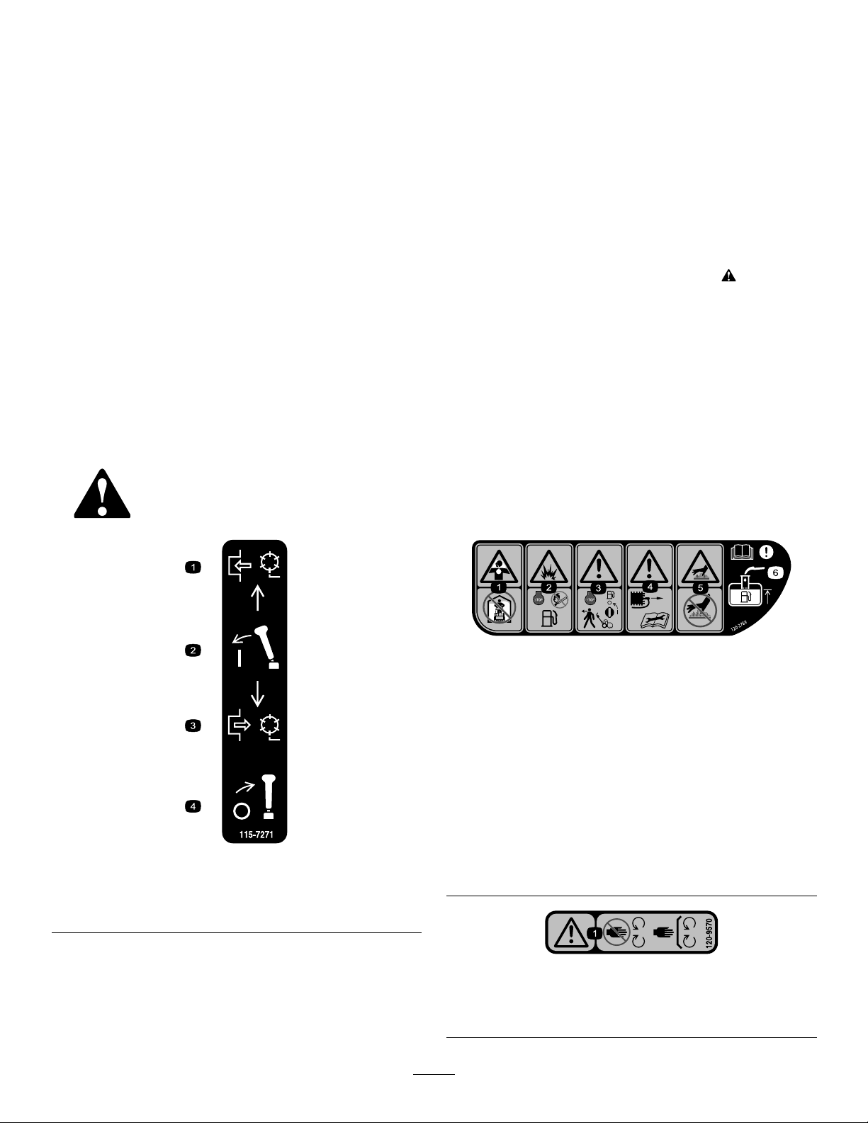
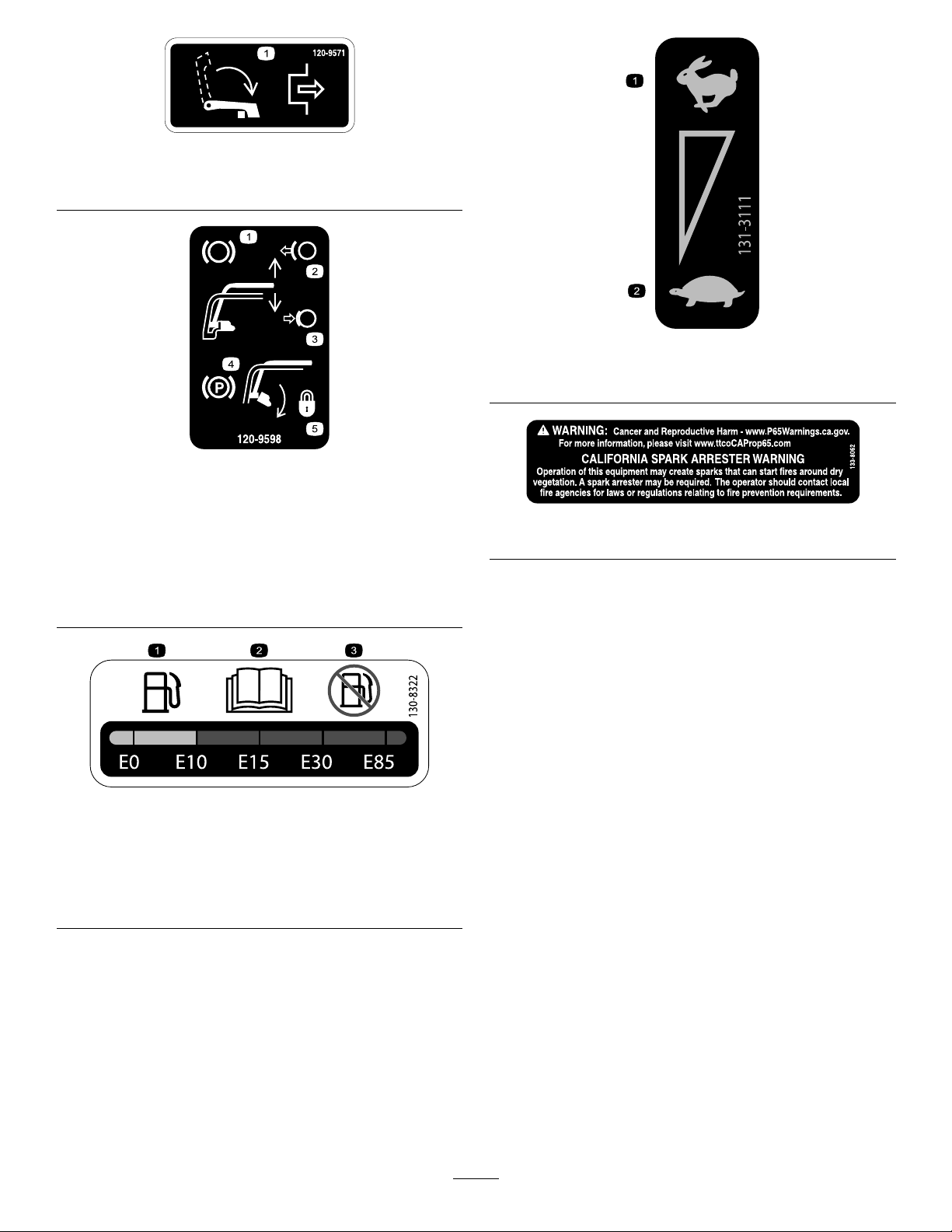
SafetyandInstructionalDecals..........................4
Setup........................................................................7
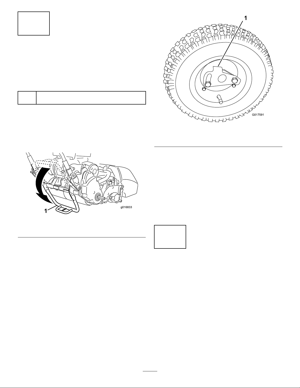
1PreparingtheTractionUnit..............................8
2InstallingtheCuttingUnittotheTraction
Unit.................................................................8
3InstallingtheHandleRetainers........................9
4InstallingtheTransportWheels........................9
5CheckingtheEngine-OilLevel.......................10
6InstallingtheProduction-YearDecal...............10
7InstallingtheGrassBasket..............................11
8BreakingintheMachine..................................11
ProductOverview...................................................12
Controls...........................................................12
Specications..................................................16
Attachments/Accessories.................................16
BeforeOperation.................................................16
BeforeOperationSafety...................................16
PerformingDailyMaintenance..........................17
CheckingtheEngine-OilLevel..........................17
FuelSpecications...........................................17
FillingtheFuelTank..........................................17
SettingtheMachinetoMatchTurf
Conditions.....................................................19
AdjustingtheHandleHeight.............................20
AdjustingtheHandleAngle...............................20
AdjustingtheThrottleControl...........................20
CheckingtheOperationoftheInterlock
Switches......................................................21
TransportingtheMachinetoaJob
Site................................................................22
UsingtheChokeLever.....................................22
OpeningandClosingtheFuel-Shutoff
Valve.............................................................22
DuringOperation.................................................23
DuringOperationSafety...................................23
StartingtheEngine...........................................24
ShuttingOfftheEngine.....................................24
ReleasingtheTransmission..............................24
OperatingTips..................................................25
AfterOperation....................................................26
AfterOperationSafety......................................26
TransportingtheMachine.................................26
Maintenance...........................................................27
MaintenanceSafety..........................................27
RecommendedMaintenanceSchedule(s)...........28
DailyMaintenanceChecklist.............................29
Pre-MaintenanceProcedures..............................30
PreparingtheMachineforMaintenance............30
EngineMaintenance...........................................30
EngineSafety...................................................30
ServicingtheEngineOil....................................30
ServicingtheAirCleaner..................................32
ServicingtheSparkPlug...................................33
FuelSystemMaintenance...................................33
CleaningtheFuel-TankScreen.........................33
ElectricalSystemMaintenance...........................34
ServicingtheTraction-InterlockSwitch
......................................................................34
ServicingtheBrake-InterlockSwitch.................34
BrakeMaintenance.............................................35
AdjustingtheService/ParkingBrake.................35
BeltMaintenance................................................35
InspectingtheReel-DriveBelt...........................35
VisuallyInspectingtheReelClutch...................36
Engaging/Disengagingthe
Transmission-BeltT ensioner.........................36
ControlsSystemMaintenance.............................37
AddingFluidtotheClutchAssembly.................37
AdjustingtheTractionControl...........................37
AdjustingtheReelControl................................38
Storage...................................................................38
StorageSafety..................................................38
StoringtheMachine..........................................38
3

Safety
Thismachinehasbeendesignedinaccordancewith
ENISO5395andANSIB71.4-2017andmeetsthese
standardswhenyouaddtherequireddecals.
GeneralSafety
Thisproductiscapableofamputatinghandsandfeet
andofthrowingobjects.
•Readandunderstandthecontentsofthis
Operator’sManualbeforestartingthemachine.
•Useyourfullattentionwhileoperatingthe
machine.Donotengageinanyactivitythat
causesdistractions;otherwise,injuryorproperty
damagemayoccur.
•Donotputyourhandsorfeetnearmoving
componentsofthemachine.
•Donotoperatethemachinewithoutallguards
andothersafetyprotectivedevicesinplaceand
functioningproperlyonthemachine.
•Keepbystandersandchildrenoutoftheoperating
area.Neverallowchildrentooperatethemachine.
•Shutofftheengine,removethekey(ifequipped),
andwaitforallmovementtostopbeforeyouleave
theoperator’sposition.Allowthemachinetocool
beforeadjusting,servicing,cleaning,orstoringit.
Improperlyusingormaintainingthismachinecan
resultininjury.Toreducethepotentialforinjury,
complywiththesesafetyinstructionsandalways
payattentiontothesafety-alertsymbol,which
meansCaution,Warning,orDanger—personalsafety
instruction.Failuretocomplywiththeseinstructions
mayresultinpersonalinjuryordeath.
SafetyandInstructionalDecals
Safetydecalsandinstructionsareeasilyvisibletotheoperatorandarelocatednearanyarea
ofpotentialdanger.Replaceanydecalthatisdamagedormissing.
decal115-7271
115-7271
1.Engagethereel.3.Disengagethereel.
2.Engagethelever.4.Disengagethelever.
decal120-2769
120-2769
1.T oxicgasinhalation
hazard—donotoperate
indoors.
4.Warning—disconnect
thesparkplugwireand
readtheOperator’s
Manualbeforeservicingor
performingmaintenance.
2.Explosionhazard—shut
offtheengineandkeep
awayfromopenames
whenrefueling.
5.Hotsurface/burn
hazard—donottouch
hotsurfaces.
3.Warning—shutoffthe
engineandturnoffthe
fuelbeforeleavingthe
machine.
6.Warning—readthe
Operator’sManual;when
addingfueltothetank,
onlylltothebottomof
thelltube.
decal120-9570
120-9570
1.Warning—stayawayfrommovingparts,keepallguards
andshieldsinplace.
4

decal120-9571
120-9571
1.Lowerthelevertodisengagethetraction.
decal120-9598
120-9598
1.Brake4.Parkingbrake
2.Releasehandleto
disengagethebrake.
5.Rotatethelatchtolockthe
parkingbrake;compress
thehandletoreleasethe
latch.
3.Compressthehandleto
engagethebrake.
decal130-8322
130-8322
1.Useonlygasolinethat
contains10%ethanolby
volume(E10)orless.
3.Donotusegasolinethat
containsmorethan10%
ethanolbyvolume(E10).
2.ReadtheOperator's
Manual.
decal131-3111
131-3111
1.Fast2.Slow
decal133-8062
133-8062
5

decal115-7274
115-7274
1.Lights(optional)3.Engine—start
2.Hourmeter4.Engine—shutoff
decal133-2335
133-2335
1.Warning—readtheOperator’sManual;
alloperatorsshouldbetrainedbefore
operatingthemachine.
3.Thrownobjecthazard—keep
bystandersaway.
5.Donottowthemachine.
2.Warning—wearhearingprotection.4.Warning—stayawayfrommoving
parts;keepallguardsandshieldsin
place.
6

Setup
LooseParts
Usethechartbelowtoverifythatallpartshavebeenshipped.
ProcedureDescriptionQty.Use
1Nopartsrequired–Preparethetractionunit(optional).
2Bolt(3/8x3/4inch)2Installthecuttingunittothetractionunit.
Handleretainer2
3Hairpincotter2Installthehandleretainers.
4Transportwheels—TransportWheelKit
(ModelNo.04123[Optional])2Installthetransportwheels.
5Nopartsrequired–Checktheengine-oillevel.
6Production-yeardecal1Installtheproduction-yeardecal
7Grassbasket1Installthegrassbasket.
8Nopartsrequired–Breakinthemachine.
MediaandAdditionalParts
DescriptionQty.Use
Operator'sManual1
EngineOwner'sManual1
CerticateofCompliance1
Readorviewthesematerialsbeforeoperatingthe
machine.
Note:Determinetheleftandrightsidesofthemachinefromthenormaloperatingposition.
7

1
PreparingtheTractionUnit
Optional—CuttingUnitModels
04251,04252,04253,or04254
NoPartsRequired
Procedure
IfyouareinstallingcuttingunitModelNo.04251,
04252,04253,or04254onthistractionunit,complete
thefollowingsteps:
1.Positionthecuttingunitonaat,levelsurface.
2.Onbothpitcharms(Figure3),measure2.3mm
(0.09inch)inonthetabsandgrinddownthe
cornerasshowninFigure4.
g034505
Figure3
1.Pitcharms
g034506
Figure4
3.Paintthebaremetaltopreventcorrosion.
2
InstallingtheCuttingUnit
totheTractionUnit
Partsneededforthisprocedure:
2Bolt(3/8x3/4inch)
Procedure
Note:Toinstalltheweightrodontoyourmachine,
refertotheinstallationinstructionsinyourcuttingunit
Operator’sManual.
1.Placethemoweronitsdrumsonalevelsurface.
2.Lowerthekickstandandpushinthelockingpin
tolockthekickstandintheSERVICEposition
(Figure5).Allowthemachinetorestonthe
lockedkickstand.
Note:PlacethekickstandintheSERVICE
positionwheneveryouremovethecuttingunit.
Thiskickstandpositionkeepsthemachinefrom
tippingbackwardontothehandle.
g018142
Figure5
1.Kickstand—STORAGE
position
3.Kickstand—SERVICE
position
2.Lockingpin
3.Pushthecuttingunitunderthetractionunitand
tothelefttoengagethetransmissioncoupling
(Figure6).
8

g000483
Figure6
1.Transmissioncoupling
4.Maneuverthemachineframeforwarduntilit
engagesthecuttingunitpivotarmsFigure7.
g032418
Figure7
1.T elescopingcoupler3.Bolt
2.Cutting-unithexshaft
5.Securethemachineframetothecuttingunit
pivotarmswiththe2bolts(3/8x3/4inch)
(Figure7).
6.MovethekickstandtotheSTORAGEposition
byreleasingthelockingpinandallowingthe
kickstandtorotateup.
7.Setthecutting-unitheightofcut;refertoyour
cuttingunitOperator’sManual.
3
InstallingtheHandle
Retainers
Partsneededforthisprocedure:
2Handleretainer
2Hairpincotter
Procedure
1.Whilesupportingthehandle,removethecable
tiesthatsecurethehandleclampstotheside
plates(Figure8).
g017005
Figure8
1.Hairpincotter2.Handleretainer
2.Pivotthehandletothedesiredoperatingposition
andinsertahandleretaineroverthehandle
clampandintothematchingholesintheside
plate(Figure8).
3.Securetheclampinpositionwithahairpincotter
(Figure8).
4.Repeattheprocedureontheoppositesideof
thehandle.
5.Adjustthehandleheighttothedesiredposition;
refertoAdjustingtheHandleHeight(page20).
Note:Themachineisshippedwiththehandle
adjustedtothelowestposition.Themachineis
traditionallyoperatedwiththehandletelescoped
outtoitsmaximumheight.
9

4
InstallingtheTransport
Wheels
Optional
Partsneededforthisprocedure:
2Transportwheels—TransportWheelKit(ModelNo.
04123[Optional])
Procedure
1.Useyourfoottopushthecenterofthekickstand
downandpulluponthelowerhandlesupport
untilthekickstandhasrotatedforwardandover
center(Figure9).
g016833
Figure9
1.Kickstand
2.Pressthewheellockingcliptowardthecenter
ofwheelandslidethewheelontothehexshaft
(Figure10).
g017591
Figure10
1.Lockingclip
3.Rotatethewheelbackandforthuntilittsonto
theaxleandthelockingclipissecuredinthe
grooveontheaxleshaft.
4.Repeattheprocedureontheoppositesideof
themachine.
5.Inatethetiresto83to103kPa(12to15psi).
6.Carefullylowerthemachineoffofthekickstand
bypushingforwardslowlyorbyliftingthelower
handlesupport,allowingthekickstandtospring
backtotheSTORAGEposition.
5
CheckingtheEngine-Oil
Level
NoPartsRequired
Procedure
Checktheengine-oillevel;refertoCheckingthe
Engine-OilLevel(page30).
10

6
Installingthe
Production-YearDecal
CEMachinesOnly
Partsneededforthisprocedure:
1Production-yeardecal
Procedure
Ifyouusethismachineinacountrythatcompliesto
CEstandards,applytheproduction-yeardecalnear
theserialplate;refertoFigure11.
g233866
Figure11
1.Serialplate2.Production-yeardecal
7
InstallingtheGrassBasket
Partsneededforthisprocedure:
1Grassbasket
Procedure
1.Graspthebasketbythehandle.
2.Guidethebasketlipbetweenthecuttingunit
sideplatesandoverthefrontroller(Figure12).
g032407
Figure12
1.Baskethooks
3.Installthebaskethooksovertheframeloop
(Figure12).
Important:Ifyoueverdropthebasket,examine
thepitch-armcontactpointsnearthelowerlip
ofthebasketfordamage(Figure13).Straighten
thembeforeusingthebasket.
Usingthebasketwithbentpitch-armcontact
pointsmaycausecontactbetweenthebasket
andcuttingunit,causingundesirednoiseand/or
damagetothebasketandcuttingunit.
g032408
Figure13
1.Pitch-armcontactpoint
11

8
BreakingintheMachine
NoPartsRequired
Procedure
Only8hoursofmowingoperationisrequiredforthe
break-inperiod.
Therstseveralhoursofoperationarecriticaltofuture
dependabilityofthemachine.Youmustmonitorthe
machineperformancecloselysothatminordifculties,
whichcouldleadtomajorproblems,arenotedand
canbecorrected.Duringtherstfewhoursof
operation,inspectthemachinefrequentlyforsignsof
oilleakage,loosefasteners,oranyothermalfunction.
Refertotheengineowner’smanualforthe
recommendedbreak-in-periodoilchangeand
maintenanceprocedures.
ProductOverview
g304912
Figure14
1.Tractionandreel-drive
engagementlever
6.Fueltank
2.Operator-presencecontrol7.Grassbasket
3.Handle8.Cuttingunit
4.Servicebrake9.Transport-wheelaxle
5.Controlpanel
Controls
g032410
Figure15
1.Openspaceforoptional
lights
5.Operator-presencecontrol
2.Parking-brakelatch6.On/Offswitch
3.Servicebrake7.Throttlecontrol
4.Handle8.Tractionandreel-drive
engagementlever
12

ThrottleControl
Thethrottlecontrol(Figure15andFigure16)is
locatedontheright,rearsideofthecontrolpanel.
Rotatethethrottletoregulatetheenginespeed.
g027738
Figure16
1.Fullspeed2.Slowspeed
TractionandReel-Drive
EngagementLever
Thetractionandreel-driveengagementlever(Figure
17)islocatedonthefrontrightsideofthecontrol
panel.
Totransportthemachine,theleverhas2positions:
NEUTRALandFORWARD.Pushingthelevertothe
traction—FORWARD(transport)positionorthe
traction—FORWARDandreeldrive—ENGAGEposition
engagesthetractiondrive(Figure17).
Note:T omovethelever,youmustrstengagethe
operator-presencecontrol.
g000494
Figure17
1.NEUTRAL3.Traction—FORWARD
(transport)
2.Traction—NEUTRALand
reeldrive—DISENGAGE
4.Traction—FORWARDand
reeldrive—ENGAGE
Tooperatethereel,theleverhas2positions:ENGAGE
andDISENGAGE.Movethetopofthelevertothe
left,thenforwardtothetraction—FORWARDand
reeldrive—ENGAGEpositiontoengagethereeland
beginmowing.Pushthelevertotherighttothe
traction—FORWARD(transport)positiontodisengage
thereelandcontinueforwardmotionorpullbackonit
tothetraction—NEUTRALandreeldrive—DISENGAGE
positiontodisengageboththereelandthetraction
drive(Figure17).
Note:Ifyoureleasetheoperator-presencecontrol,
theleverreturnstoneutralandthemachinestops.
13

ServiceBrake
Theservicebrake(Figure18)islocatedontheleft
frontsideofthehandle.Pullingbacktheleverapplies
theservicebrake.
Youmustdisengagethebrakebeforeyouengagethe
tractiondrive.Ifyouoperatethemachinewiththe
brakeengaged,themachinemoves,butwithahigh
resistanceandincreasedpowerconsumption.
g016853
Figure18
1.Parking-brakelatch2.Servicebrake
Parking-BrakeLatch
Usetheparking-brakelatch(Figure18)withthe
servicebrake.Rotatetheparking-brakelatchtoward
thebrakehandletoholdtheservicebrakeinplace.
Pullthebrakelevertorelease.
Note:Youcannotmovethetraction-controllever
whilethelatchisengaged.
On/OffSwitch
TheOn/Offswitch(Figure15)islocatedonthetopof
thecontrolpanel.MovetheswitchtotheONposition
tostarttheengineandtheOFFpositiontoshutoff
theengine.
Operator-PresenceControl(OPC)
Youmustengagetheoperator-presencecontrol
(Figure15)beforeyouengagethetractionlever.Ifyou
releasetheOPCduringoperation,thetractionlever
returnstoneutralandtheenginecontinuestorun.
ChokeLever
Thechokelever(Figure19)islocatedontheleftfront
oftheengine.Usethelevertoaidinstartingacold
engine;refertoUsingtheChokeLever(page22).
g265059
Figure19
1.Chokelever3.Recoil-starterhandle
2.Fuel-shutoffvalve
Fuel-ShutoffValve
Thefuel-shut-offvalveislocatedonthesideofthe
enginebelowthechokecontrol(Figure19).
Note:Closethefuel-shutoffvalvewhenthemachine
isnotusedforafewdays,duringtransporttoand
fromthejobsite,orwhenthemachineisparked
insideabuilding;refertoOpeningandClosingthe
Fuel-ShutoffValve(page22).
14

Recoil-StarterHandle
Pulltherecoil-starterhandle(Figure19)tostartthe
engine.
Kickstand
Thekickstand(Figure21)ismountedtotherearof
themachine.Usethekickstandwhenyouinstallor
removethetransportwheelsorthecuttingunit.
•Tousethekickstandtoinstallthetransportwheels,
lowerthekickstandtothegroundandstepdown
ontheloopwhilepullingupandbackonthe
lower-centerhandle(Figure20).
CAUTION
Themachineisheavyandcancauseback
strainifliftedimproperly.
Putyourfootpressuredownonthe
kickstandloopanduseonlythe
lower-centerhandletoraisethemachine.
Attemptingtoraisethemachineontothe
kickstandanyotherwaycancauseinjury.
g018793
Figure20
1.Lower-centerhandle2.Kickstandloop
g239955
Figure21
1.Kickstand2.Kickstandloop
•Topreventthemachinefromtippingbackward
whenremovingthereel,lowerthekickstandand
pushinthelockingpintolockitintheSERVICE
position(Figure22).
g018142
Figure22
1.Kickstand—STORAGE
position
3.Kickstand—SERVICE
position
2.Lockingpin
15

Specications
2120TractionUnit
Width90.1cm(35-1/2inches)
Height104.8cm(41-1/4inches)
Lengthwithbasket152.4cm(60inches)
NetWeight(with
11-bladecuttingunit
andgrassbasket
installed)
117.9kg(260lb)
Widthofcut53.3cm(21inches)
Heightofcut1.5to7.5mm(1/16to19/64inch)with
Micro-Cutbedknife
ClipfrequencyAdjustable(refertoyourcuttingunit
Operator’sManual)
Attachments/Accessories
AselectionofT oroapprovedattachmentsand
accessoriesisavailableforusewiththemachine
toenhanceandexpanditscapabilities.Contact
yourAuthorizedServiceDealerorauthorizedT oro
distributororgotowww.T oro.comforalistofall
approvedattachmentsandaccessories.
Toensureoptimumperformanceandcontinuedsafety
certicationofthemachine,useonlygenuineToro
replacementpartsandaccessories.Replacement
partsandaccessoriesmadebyothermanufacturers
couldbedangerous,andsuchusecouldvoidthe
productwarranty.
Operation
BeforeOperation
Note:Determinetheleftandrightsidesofthe
machinefromthenormaloperatingposition.
BeforeOperationSafety
GeneralSafety
•Neverallowchildrenoruntrainedpeopleto
operateorservicethemachine.Localregulations
mayrestricttheageoftheoperator.Theowner
isresponsiblefortrainingalloperatorsand
mechanics.
•Becomefamiliarwiththesafeoperationofthe
equipment,operatorcontrols,andsafetysigns.
•Shutoffthemachine,removethekey(ifequipped),
andwaitforallmovementtostopbeforeyouleave
theoperator’sposition.Allowthemachinetocool
beforeadjusting,servicing,cleaning,orstoringit.
•Knowhowtostopthemachineandshutoffthe
machinequickly.
•Checkthatoperator-presencecontrols,safety
switches,andsafetyprotectivedevicesare
attachedandfunctioningproperly.Donotoperate
themachineunlesstheyarefunctioningproperly.
•Inspecttheareawhereyouwillusethemachine
andremoveallobjectsthatthemachinecould
throw.
FuelSafety
•Useextremecareinhandlingfuel.Itisammable
anditsvaporsareexplosive.
•Extinguishallcigarettes,cigars,pipes,andother
sourcesofignition.
•Useonlyanapprovedfuelcontainer.
•Donotremovethefuelcaporaddfueltothetank
whiletheengineisrunningorhot.
•Donotaddordrainfuelinanenclosedspace.
•Donotstorethemachineorfuelcontainerwhere
thereisanopename,spark,orpilotlight,such
asonawaterheaterorotherappliance.
•Ifyouspillfuel,donotattempttostarttheengine;
avoidcreatingasourceofignitionuntilthefuel
vaporshavedissipated.
•Donotllcontainersinsideavehicleoronatruck
ortrailerbedwithaplasticliner.Alwaysplace
containersontheground,awayfromthevehicle
beforelling.
•Removeequipmentfromthetruckortrailerand
refuelitontheground.Ifthisisnotpossible,refuel
16

suchequipmentwithaportablecontainerrather
thanfromafuel-dispensernozzle.
•Keepthenozzleincontactwiththerimofthefuel
tankorcontaineroperatingatalltimesuntilfueling
iscomplete.
PerformingDaily
Maintenance
Performthedailymaintenanceprocedures;referto
DailyMaintenanceChecklist(page29).
CheckingtheEngine-Oil
Level
Checktheengine-oillevelbeforeeachuseorevery
8operatinghours,refertoCheckingtheEngine-Oil
Level(page30).
FuelSpecications
Fueltankcapacity:2.0L(0.59USgallons)
Recommendedfuel:Unleadedgasolinewithan
octaneratingof87orhigher((R+M)/2ratingmethod)
Ethanol:Gasolinewithupto10%ethanol(gasohol)
or15%MTBE(methyltertiarybutylether)byvolume
isacceptable.EthanolandMTBEarenotthesame.
Gasolinewith15%ethanol(E15)byvolumeisnot
approvedforuse.
•Neverusegasolinethatcontainsmorethan
10%ethanolbyvolume,suchasE15(contains
15%ethanol),E20(contains20%ethanol),orE85
(containsupto85%ethanol).
•Donotusegasolinecontainingmethanol.
•Donotstorefueleitherinthefueltankorfuel
containersoverthewinterunlessyouuseafuel
stabilizer.
•Donotaddoiltogasoline.
•Forbestresults,useonlyclean,fresh(lessthan
30daysold)fuel.
•Usingunapprovedgasolinemaycause
performanceproblemsand/orenginedamage,
whichmaynotbecoveredunderthewarranty.
FillingtheFuelTank
DANGER
Incertainconditions,fuelisextremely
ammableandhighlyexplosive.Areor
explosionfromfuelcanburnyouandothers
andcandamageproperty.
•Fillthefueltankoutdoors,inanopenarea,
whentheengineiscold.Wipeupanyfuel
thatspills.
•Neverllthefueltankinsideanenclosed
trailer.
•Donotllthefueltankcompletelyfull.
Addfueltothefueltankuntilthelevelis6
to13mm(1/4to1/2inch)belowthebottom
ofthellerneck.Thisemptyspaceinthe
tankallowsfueltoexpand.
•Neversmokewhenhandlingfuel,andstay
awayfromanopenameorwherefuel
fumesmaybeignitedbyaspark.
•Storefuelinanapprovedcontainerand
keepitoutofthereachofchildren.Never
buymorethana30-daysupplyoffuel.
•Donotoperatewithoutentireexhaust
systeminplaceandinproperworking
condition.
DANGER
Incertainconditionsduringfueling,static
electricitycanbereleased,causingaspark
whichcanignitethefuelvapors.Areor
explosionfromfuelcanburnyouandothers
andcandamageproperty.
•Alwaysplacefuelcontainersontheground
awayfromyourvehiclebeforelling.
•Donotllfuelcontainersinsideavehicle
oronatruckortrailerbedbecauseinterior
carpetsorplastictruck-bedlinersmay
insulatethecontainerandslowthelossof
anystaticcharge.
•Whenpractical,removeequipmentfrom
thetruckortrailerandfuelitonthe
ground.Ifthisisnotpossible,thenfuel
suchequipmentwithaportablecontainer
ratherthanfromafuel-dispensernozzle.
•Ifyoumustuseafuel-dispensernozzle,
keepthenozzleincontactwiththerimof
thefueltankorcontaineropeningatall
timesuntilfuelingiscomplete.
17

WARNING
Fuelisharmfulorfatalifswallowed.
Long-termexposuretovaporscancause
seriousinjuryandillness.
•Avoidprolongedbreathingofvapors.
•Keepyourfaceawayfromthenozzleand
fueltankorconditionerbottleopening.
•Avoidcontactwithskin;washoffspills
withsoapandwater.
1.Cleanaroundthefuel-tankcapandremovethe
capfromthetank(Figure23).Fillthefueltank
tothebottomofthell-neckopening.
Important:Donotoverllthetankwithfuel.
g265976
Figure23
1.Fuel-tankcap
2.Installthefuel-tankcapandwipeupanyspilled
fuel.
18

SettingtheMachinetoMatchTurfConditions
Usethefollowingtabletosetthemachinetomatchturfconditions.
Bedbars:StandardandOptional(Flex/eFlex2120Machines)
PartNumberDescriptionAggressivenessComments
106-2468-01Non-AggressiveLessRed,Standard
99-3794-03AggressiveMoreBlack
Bedbars:StandardandOptional(Flex/eFlex1820Machines)
110-2282-01Non-AggressiveLessRed,Standard
110-2281-03AggressiveMoreBlack
Bedknives:StandardandOptional(Flex/eFlex2120Machines)
PartNumberDescriptionHeight-of-cutRangeComments
115-1880Microcut-EdgeMax1.6to3.2mm(0.062to0.125inch)Standard
93-4262Microcut1.6to3.2mm(0.062to0.125inch)
108-4303ExtendedMicrocut1.6to3.2mm(0.062to0.125inch)Lessaggressive
115-1881Tournament-EdgeMax3.2to6.4mm(0.125to0.25inch)
93-4263Tournament3.2to6.4mm(0.125to0.25inch)
108-4302ExtendedTournament3.2to6.4mm(0.125to0.25inch)Lessaggressive
93-4264LowCut6.4mm(0.25inch)andup
Bedknives:StandardandOptional(Flex/eFlex1820Machines)
117-1530Microcut-EdgeMax1.6to3.2mm(0.062to0.125inch)Standard
98-7261Microcut1.6to3.2mm(0.062to0.125inch)
110-2300ExtendedMicrocut1.6to3.2mm(0.062to0.125inch)Lessaggressive
98-7260Tournament3.2to6.4mm(0.125to0.25inch)
117-1532Tournament-EdgeMax3.2to6.4mm(0.125to0.25inch)
110-2301LowCut6.4mm(0.25inch)andup
Rollers(Flex/eFlex2120Machines)
PartNumberDescriptionDiameter/MaterialComments
04255NarrowWiehle6.4cm(2.5inches)/AluminumNarrowspacedgrooves
04256WideWiehle6.4cm(2.5inches)/AluminumMorepenetration,widespacedgrooves
04257FullRoller6.4cm(2.5inches)/SteelLeastpenetration
04258NarrowWiehle—Long6.4cm(2.5inches)/AluminumMoreedgesupport;4.3cm(1.7inches)longer
04267Paspalum6.4cm(2.5inches)/AluminumLesspenetration,softenednarrowspacedgrooves
115-7356RearRoller5.1cm(2.0inches)/AluminumStandardrear
120-9595RearRoller5.1cm(2.0inches)/SteelSteelrear
Rollers(Flex/eFlex1820Machines)
120-9607NarrowWiehle6.4cm(2.5inches)/AluminumNarrowspacedgrooves
120-9609WideWiehle6.4cm(2.5inches)/AluminumMorepenetration,widespacedgrooves
120-9611FullRoller6.4cm(2.5inches)/SteelLeastpenetration
121-4681NarrowWiehle—Long6.4cm(2.5inches)/AluminumMoreedgesupport;4.3cm(1.7inches)longer
120-9605RearRoller5.1cm(2.0inches)/AluminumStandardrear
19

AdjustingtheHandle
Height
Note:Themachineisshippedwiththehandle
adjustedtothelowestposition.Themachineis
normallyoperatedwiththehandletelescopedoutto
itsmaximumheight.
1.Loosenthe3carriageboltsandnutssecuring
eachsideofthehandleinthehandleclamps
(Figure24).
g016851
Figure24
1.Handleclamp3.Carriagebolts
2.Nut
2.Pulluponthehandleslowlyandevenlyoneach
sideuntilitisinthedesiredoperatingposition.
3.Tightenthecarriageboltsandnutstolockthe
adjustment.
AdjustingtheHandleAngle
1.Removethehairpincottersfromthehandle
retainersoneachsideofthemachine(Figure
25).
g017005
Figure25
1.Hairpincotter2.Handleretainer
2.Whilesupportingthehandle,removethehairpin
cottersfromeachsideandpivotthehandleto
thedesiredoperatingposition(Figure25).
3.Installthehandleretainersandhairpincotters.
AdjustingtheThrottle
Control
1.Removetheconsolecover.
2.Loosenthe2fastenerssecuringthethrottle
control(Figure26).
g027739
Figure26
1.Fasteners2.Throttlecontrol
3.Adjustthethrottlecontroltothedesiredposition.
4.Tightenthethrottle-controlfasteners.
5.Installthepreviouslyremovedconsolecover.
20
This manual suits for next models
1
Table of contents
Other Toro Lawn Mower manuals

Toro
Toro TimeCutter 6000 Series User manual

Toro
Toro Recycler 20999 User manual

Toro
Toro 30410 User manual

Toro
Toro CT2240 User manual

Toro
Toro 74262CP User manual

Toro
Toro Groundsmaster 4500-D User manual

Toro
Toro 30072 User manual

Toro
Toro Z Master 8000 Series User manual

Toro
Toro 03180 User manual

Toro
Toro Greensmaster 3250-D 04383 User manual
Popular Lawn Mower manuals by other brands

Scag Power Equipment
Scag Power Equipment TIGER CAT STC48V-19KAI Operator's manual

GÜDE
GÜDE 460/40-5.0S-R Translation of the original instructions

Lumag
Lumag HGS50058 Operator's manual

Cramer
Cramer RM2700 Operator's manual

Agri-Fab
Agri-Fab 45-03052 owner's manual

Villager
Villager V 722 Original instruction manual