Toro Groundsmaster 228-D User manual

Operator’s Manual
Language Name (Language Abbreviation)
Form No. 3325–395
Groundsmaster 228–D
4 Wheel Drive Traction Unit
Model No. 30242–210000001 and Up

2
All Rights Reserved
Printed in the USA
2001 by The Toro Company
8111 Lyndale Avenue South
Bloomington, MN 55420-1196
The engine exhaust from this product contains
chemicals known to the State of California to cause
cancer, birth defects, or other reproductive harm.
Warning
Important The engine in this product is not equipped
with a spark arrester muffler. It is a violation of California
Public Resource Code Section 4442 to use or operate this
engine on any forest-covered, brush-covered, or
grass-covered land as defined in CPRC 4126. Other states
or federal areas may have similar laws.
Contents
Page
Contents 2. . . . . . . . . . . . . . . . . . . . . . . . . . . . . . . . . . . .
Introduction 3. . . . . . . . . . . . . . . . . . . . . . . . . . . . . . . . .
Safety 3. . . . . . . . . . . . . . . . . . . . . . . . . . . . . . . . . . . . . .
Safe Operating Practices 3. . . . . . . . . . . . . . . . . . . .
Toro Mower Safety 4. . . . . . . . . . . . . . . . . . . . . . . .
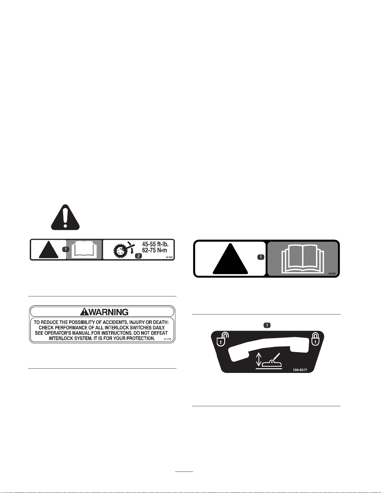
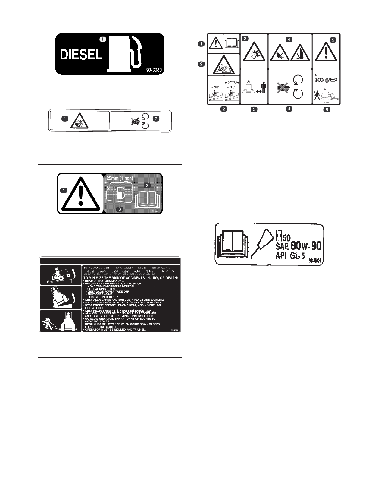
Safety and Instruction Decals 6. . . . . . . . . . . . . . . . .
Specifications 12. . . . . . . . . . . . . . . . . . . . . . . . . . . . . . . .
General Specifications 12. . . . . . . . . . . . . . . . . . . . .
Measurements 13. . . . . . . . . . . . . . . . . . . . . . . . . . . .
Optional Equipment 13. . . . . . . . . . . . . . . . . . . . . . . .
Setup 14. . . . . . . . . . . . . . . . . . . . . . . . . . . . . . . . . . . . . .
Install Rear Wheels 15. . . . . . . . . . . . . . . . . . . . . . . .
Install Steering Wheel 15. . . . . . . . . . . . . . . . . . . . . .
Install Seat 15. . . . . . . . . . . . . . . . . . . . . . . . . . . . . . .
3Install Seat Belt 17. . . . . . . . . . . . . . . . . . . . . . . . . .
Install Manual Tube 17. . . . . . . . . . . . . . . . . . . . . . . .
Install Rops 17. . . . . . . . . . . . . . . . . . . . . . . . . . . . . . .
Connect Battery 18. . . . . . . . . . . . . . . . . . . . . . . . . . .
Check Tire Pressure 18. . . . . . . . . . . . . . . . . . . . . . . .
Install Rear Weight 18. . . . . . . . . . . . . . . . . . . . . . . . .
Before Operating 19. . . . . . . . . . . . . . . . . . . . . . . . . . . . .
Check Engine Oil 19. . . . . . . . . . . . . . . . . . . . . . . . . .
Check Cooling System 19. . . . . . . . . . . . . . . . . . . . . .
Check Hydraulic System Fluid 19. . . . . . . . . . . . . . .
Fill Fuel Tank 20. . . . . . . . . . . . . . . . . . . . . . . . . . . . .
Check Rear Axle 21. . . . . . . . . . . . . . . . . . . . . . . . . .
Check Bidirectional Clutch Lubricant 21. . . . . . . . . .
Page
Controls 22. . . . . . . . . . . . . . . . . . . . . . . . . . . . . . . . . . . .
Operation 24. . . . . . . . . . . . . . . . . . . . . . . . . . . . . . . . . . .
Starting/Stopping Engine 24. . . . . . . . . . . . . . . . . . . .
Bleeding Fuel System 24. . . . . . . . . . . . . . . . . . . . . .
Checking Interlock System 25. . . . . . . . . . . . . . . . . .
Operating Characteristics 25. . . . . . . . . . . . . . . . . . . .
Pushing Or Towing Traction Unit 25. . . . . . . . . . . . .
Lubrication 26. . . . . . . . . . . . . . . . . . . . . . . . . . . . . . . . . .
Greasing Bearings And Bushings 26. . . . . . . . . . . . .
Service Interval Chart 28. . . . . . . . . . . . . . . . . . . . . .
Maintenance 29. . . . . . . . . . . . . . . . . . . . . . . . . . . . . . . . .
Recommended Maintenance Schedule 29. . . . . . . . .
Daily Maintenance Checklist 30. . . . . . . . . . . . . . . . .
Maintenance 31. . . . . . . . . . . . . . . . . . . . . . . . . . . . . . . . .
General Air Cleaner Maintenance 31. . . . . . . . . . . . .
Servicing Air Cleaner 31. . . . . . . . . . . . . . . . . . . . . . .
Cleaning Radiator And Screen 31. . . . . . . . . . . . . . . .
Changing Engine Oil And Filter 32. . . . . . . . . . . . . .
Servicing Fuel System 32. . . . . . . . . . . . . . . . . . . . . .
Bleeding Air From Injectors 33. . . . . . . . . . . . . . . . .
Alternator Belt 33. . . . . . . . . . . . . . . . . . . . . . . . . . . .
Adjusting Throttle 34. . . . . . . . . . . . . . . . . . . . . . . . .
PTO Belt 34. . . . . . . . . . . . . . . . . . . . . . . . . . . . . . . . .
PTO Clutch Adjustment 34. . . . . . . . . . . . . . . . . . . . .
Adjusting Transmission For Neutral 35. . . . . . . . . . .
Adjusting the Parking Brake Interlock Switch 35. . .
Changing Hydraulic Oil And Filter 36. . . . . . . . . . . .
Adjusting Service Brakes 37. . . . . . . . . . . . . . . . . . . .
Changing Rear Axle Lubricant 37. . . . . . . . . . . . . . .
Changing Bidirectional Clutch Lubricant 38. . . . . . .
Rear Wheel Toe–in 38. . . . . . . . . . . . . . . . . . . . . . . . .
Servicing Battery 38. . . . . . . . . . . . . . . . . . . . . . . . . .
Wiring Harness Service 38. . . . . . . . . . . . . . . . . . . . .
Fuses 38. . . . . . . . . . . . . . . . . . . . . . . . . . . . . . . . . . . .
Hydraulic Schematic 39. . . . . . . . . . . . . . . . . . . . . . .
Electrical Schematic 40. . . . . . . . . . . . . . . . . . . . . . . .
Storage 41. . . . . . . . . . . . . . . . . . . . . . . . . . . . . . . . . . . . .
Traction Unit 41. . . . . . . . . . . . . . . . . . . . . . . . . . . . .
Engine 41. . . . . . . . . . . . . . . . . . . . . . . . . . . . . . . . . .
The Toro General Commercial Products Warranty 44. . .

3
Introduction
Read this manual carefully to learn how to operate and
maintain your product properly. The information in this
manual can help you and others avoid injury and product
damage. Although Toro designs and produces safe
products, you are responsible for operating the product
properly and safely.
Whenever you need service, genuine Toro parts, or
additional information, contact an Authorized Service
Dealer or Toro Customer Service and have the model and
serial numbers of your product ready. Figure 1 illustrates
the location of the model and serial numbers on the
product.
1
Figure 1
1. Location of the model and serial numbers
Write the product model and serial numbers in the space
below:
Model No.
Serial No.
This manual identifies potential hazards and has special
safety messages that help you and others avoid personal
injury and even death. Danger, Warning, and Caution are
signal words used to identify the level of hazard. However,
regardless of the hazard, be extremely careful.
Danger signals an extreme hazard that will cause serious
injury or death if you do not follow the recommended
precautions.
Warning signals a hazard that may cause serious injury or
death if you do not follow the recommended precautions.
Caution signals a hazard that may cause minor or moderate
injury if you do not follow the recommended precautions.
This manual uses two other words to highlight information.
Important calls attention to special mechanical
information and Note: emphasizes general information
worthy of special attention.
Safety
This machine meets or exceeds the B71.4 1999
specifications of the American National Standards
Institute, in effect at time of production.
Note: The addition of attachments made by other
manufacturers that do not meet American National
Standards Institute certification will cause
noncompliance of this machine.
Improper use or maintenance by the operator or
owner can result in injury. To reduce the potential
for injury, comply with these safety instructions
and always pay attention to the safety alert
symbol, which means CAUTION, WARNING, or
DANGERpersonal safety instruction." Failure to
comply with the instruction may result in personal
injury or death.
Safe Operating Practices
The following instructions are from ANSI standard
B71.41999.
Training
•Read the Operator’s Manual and other training material.
If the operator(s) or mechanic(s) can not read English it
is the owner’s responsibility to explain this material to
them.
•Become familiar with the safe operation of the
equipment, operator controls, and safety signs.
•All operators and mechanics should be trained. The
owner is responsible for training the users.
•Never let children or untrained people operate or
service the equipment. Local regulations may restrict
the age of the operator.
•The owner/user can prevent and is responsible for
accidents or injuries occurring to himself or herself,
other people or property.
Preparation
•Evaluate the terrain to determine what accessories and
attachments are needed to properly and safely perform
the job. Only use accessories and attachments approved
by the manufacturer.

4
•Wear appropriate clothing including hard hat, safety
glasses and ear protection. Long hair, loose clothing or
jewelry may get tangled in moving parts.
•Inspect the area where the equipment is to be used and
remove all objects such as rocks, toys and wire which
can be thrown by the machine.
•Use extra care when handling diesel and other fuels.
They are flammable and vapors are explosive.
•Use only an approved container
•Never remove fuel cap or add fuel with engine
running. Allow engine to cool before refueling.
Do not smoke.
•Never refuel or drain the machine indoors.
•Check that operator’s presence controls, safety switches
and shields are attached and functioning properly. Do
not operate unless they are functioning properly.
Operation
•Never run an engine in an enclosed area.
•Only operate in good light, keeping away from holes
and hidden hazards.
•Be sure all drives are in neutral and parking brake is
engaged before starting engine. Only start engine from
the operator’s position. Use seat belts if provided.
•Slow down and use extra care on hillsides. Be sure to
travel in the recommended direction on hillsides. Turf
conditions can affect the machine’s stability. Use
caution while operating near drop–offs.
•Slow down and use caution when making turns and
when changing directions on slopes.
•Never raise deck with the blades running.
•Never operate with the PTO shield, or other guards not
securely in place. Be sure all interlocks are attached,
adjusted properly, and functioning property.
•Do not change the engine governor setting or overspeed
the engine.
•Stop on level ground, lower implements, disengage
drives, engage parking brake (if provided), shut off
engine before leaving the operator’s position for any
reason.
•Stop equipment and inspect blades after striking objects
or if an abnormal vibration occurs. Make necessary
repairs before resuming operations.
•Keep hands and feet away from the cutting units.
•Look behind and down before backing up to be sure of
a clear path.
•Never carry passengers and keep pets and bystanders
away.
•Slow down and use caution when making turns and
crossing roads and sidewalks. Stop blades if not
mowing.
•Do not operate the mower under the influence of
alcohol or drugs
•Use care when loading or unloading the machine into a
trailer or truck
•Use care when approaching blind corners, shrubs, trees,
or other objects that may obscure vision.
Maintenance and storage
•Disengage drives, lower implement, set parking brake,
stop engine and remove key. Wait for all movement to
stop before adjusting, cleaning or repairing.
•Clean grass and debris from cutting units, drives,
mufflers, and engine to help prevent fires. Clean up oil
or fuel spillage.
•Let engine cool before storing and do not store near
flame.
•Do not store fuel near flames or drain indoors.
•Park machine on level ground. Never allow untrained
personnel to service machine.
•Use jack stands to support components when required.
•Carefully release pressure from components with stored
energy.
•Disconnect battery before making any repairs.
Disconnect the negative terminal first and the positive
last. Reconnect positive first and negative last.
•Use care when checking blades. Wrap the blade(s) or
wear gloves, and use caution when servicing them.
Only replace blades. Never straighten or weld them.
•Keep hands and feet away from moving parts. If
possible, do not make adjustments with the engine
running.
•Charge batteries in an open well ventilated area, away
from spark and flames. Unplug charger before
connecting or disconnecting from battery. Wear
protective clothing and use insulated tools.
•Keep all parts in good working condition and all
hardware tightened. Replace all worn or damaged
decals.
Toro Mower Safety
The following list contains safety information
specific to Toro products or other safety
information that you must know that is not
included in the ANSI standards.

5
This product is capable of amputating hands and feet and
throwing objects. Always follow all safety instructions to
avoid serious injury or death.
This product is designed for cutting and recycling grass.
Any use for purposes other than these could prove
dangerous to user and bystanders.
General Operation
•Allow only responsible adults who are familiar with the
instructions to operate the machine.
•Be sure the area is clear of other people before mowing.
Stop the machine if anyone enters the area.
•Do not mow in reverse unless absolutely necessary.
Always look down and behind before and while
backing.
•Slow down before turning. Sharp turns on any terrain
may cause loss of control.
•Turn off blades when not mowing.
•Keep hands, feet, hair and loose clothing away from
attachment discharge area, underside of mower and any
moving parts while engine is running.
•Mow only in daylight or good artificial light.
•Watch for traffic when operating near or crossing
roadways.
•Do not touch equipment or attachment parts which may
be hot from operation. Allow to cool before attempting
to maintain, adjust or service.
•Before operating a machine with ROPS (roll over
protection) be certain the seat belts are attached and seat
is latched to prevent the seat from pivoting forward.
•Use only Toro-approved attachments. Warranty may be
voided if used with unapproved attachments.
Slope Operation
Slopes and ramps are a major factor related to
loss-of-control and tip-over accidents, which can result in
severe injury or death. All slopes and ramps require extra
caution. If you cannot back up the slope or if you feel
uneasy on it, do not mow it.
DO
•If a steep slope must be ascended, back up the hill, and
drive forward down the hill, keeping the machine in
gear.
•Remove obstacles such as rocks, tree limbs, etc. from
the mowing area. Watch for holes, ruts or bumps, as
uneven terrain could overturn the machine. Tall grass
can hide obstacles.
•Use slow speed so that you will not have to stop while
on the slope.
•Follow the manufacturer’s recommendations for wheel
weights or counterweights to improve stability.
•Use extra care with other attachments. These can
change the stability of the machine.
•Keep all movement on slopes slow and gradual. Do not
make sudden changes in speed or direction.
•Avoid starting or stopping on a slope. If tires lose
traction, disengage the blades and proceed slowly
straight down the slope. Avoid raising side decks on a
slope.
•When operating machine on slopes, banks or near drop
offs, always have ROPS (roll over protection) installed.
•When operating a machine with ROPS (roll over
protection) always use seat belt.
•Be certain that the seat belt can be released quickly if
the machine is driven or rolls into ponds or water.
•Check carefully for overhead clearances (i.e. branches,
doorways, electrical wires) before driving under any
objects and do not contact them.
DO NOT
•Do not mow slopes exceeding 15 degrees.
•Avoid turning on slopes. If you must turn, turn slowly
and gradually downhill, if possible.
•Do not mow near drop-offs, ditches, or embankments.
The machine could suddenly turn over if a wheel goes
over the edge of a cliff or ditch, or if an edge caves in.
•Do not mow on wet grass. Reduced traction could cause
sliding.
•Do not try to stabilize the machine by putting your
foot on the ground.
Service
•Never store the machine or fuel container inside where
there is an open flame, such as near a water heater or
furnace.
•Keep nuts and bolts tight, especially the blade
attachment bolts. Keep equipment in good condition.
•Never tamper with safety devices. Check safety systems
for proper operation before each use.
•Use only genuine replacement parts to ensure that
original standards are maintained.
•Check brake operation frequently. Adjust and service as
required.

6
•Battery acid is poisonous and can cause burns. Avoid
contact with skin, eyes and clothing. Protect your face,
eyes and clothing when working with a battery.
•Battery gases can explode. Keep cigarettes, sparks and
flames away from battery.
•Hydraulic fluid escaping under pressure can penetrate
the skin and cause injury. Use cardboard or paper to
find hydraulic leaks. Never use your hands.
Sound Pressure Level
This unit has an equivalent continuous A-weighted sound
pressure at the operator ear of: 90 dB(A), based on
measurements of identical machines per Directive
84/538/EEC and amendments.
Sound Power Level
This unit has a sound power level of: 105 dB(A) 1 pW,
based on measurements of identical machines per Directive
84/538/EEC and amendments.
Vibration Level
Hand-Arm
This unit does not exceed a vibration level of 2.5 m/sat
the hands based on measurements of identical machines per
ISO 5349 procedures.
Whole Body
This unit does not exceed a vibration level of .5 m/sat the
posterior based on measurements of identical machines per
ISO 2631 procedures.
Safety and Instruction Decals
Safety decals and instructions are easily visible to the operator and are located near any area
of potential danger. Replace any decal that is damaged or lost.
93–7830
1. Danger–See operator’s manual
2. Wheel torque specifications
67–1710
Cover with 93–7841 for CE
93–7841
Use to cover 67–1710 for CE
1. Danger–See operator’s manual
100–6577
1. Lock – Unlock deck
service lock

7
93–6680
1. Diesel fuel
93–7272
1. Fan blades can cause
injury 2. Stay away from moving
parts
93–7822
1. Danger
2. See Operator’s manual 3. Fill fuel tank to 1” from
bottom of filler neck
92–5774
Cover with 93–7804 for CE
93–7804
Apply over 92–5774 for CE
1. Danger–Read operator’s
manual
2. Tipping hazard–Go slow
and avoid sharp turns on
slopes to avoid rollover.
Deck must be lowered
when going down slopes
for steering control.
Always wear seat belts
with ROPS.
3. Thrown object
hazard–keep bystanders
away
4. Cutting hazard to hands
or feet–stay away from
rotating blades or moving
parts.
5. Danger–set the parking
brake, stop the engine
and remove the key
before leaving the
operator’s position.
93–6697
1. Read operator’s manual
for lubrication intervals

8
100–6574
1. Hot surface stay away 2. Stay away from moving
parts
93-7276
1. Explosion hazard—wear eye protection.
2. Caustic liquid hazard—flush with water and seek first aid.
3. Fire hazard—no sparks, flame, or smoking
4. Poison—keep children a safe distance from the battery.
93–7840
1. Coolant level
2. Hot surface–keep a safe
distance
3. Danger–rear the
operator’s manual
4. Explosion hazard–stay
away
93–6668
1. The battery contains lead.
Do not throw it in the
garbage.
105–2509
Cover with 105–2511 for CE
105–2511
Use to cover 105–2509 for CE
1. Read operator’s manual
for starting instructions

9
93–7834
1. No step
2. Traction pedal
3. Traction–forward
4. Traction–reverse
5. Danger – Shut off PTO
prior to raising decks
6. Danger – Do not operate
decks when they are in
raised position
93–7833
1. Throttle control
2. Throttle–fast
3. Throttle–slow
4. Tipping hazard–Lower
deck when going down
slopes greater than 10
degrees
5. Tipping hazard–Lower
deck when going down
slopes greater than 10
degrees
6. Danger–tipping hazard
7. Lift lever–raise position
8. Lift lever–lower position
9. Lift lever–float position

10
100–6581
1. To lock parking
brake–Latch pedals
together, apply brake
pedals and pull up on
knob
2. To unlock parking
brake–step on brake
pedals
100–6552
1. Refer to Operator’s
Manual for Engine oil
specifications
Part No. 104–3484
1. See the operator’s manual

11
Part No. 105–0054
1. Headlights–off
2. Headlights–on 3. PTO–off
4. PTO–on 5. Engine coolant temperature
6. Engine–start 7. Engine–stop

12
Specifications
Note: Specifications and design subject to change without notice.
General Specifications
Engine Kubota three cylinder, 4 cycle liquid cooled diesel engine. 26 hp @ 3000. Engine
governed to 3200–3250 rpm high idle, no load.
Air Cleaner Heavy duty remote mounted.
Fuel Tank Capacity 8.5 gal. (32 l) Equipped with a fuel filter/water separator to capture water in the fuel.
Fuel Pump 12 volt electric (transistor type) w/replaceable fuel filter.
Cooling System 7 qt (6.6 l) capacity. Remote mounted expansion tank 1 qt (0.946 l) capacity.
System contains a 50/50 mix of ethylene glycol anti-freeze and water. Front
mounted air/oil cooler used to cool hydraulic oil for the hydrostatic transmission.
Electrical 12 volt with 530 cold cranking amps at 0F and 75 minute reserve capacity at
80F.
Drive Coupling Transmission driven by steel shaft with flexible rubber couplings at each end.
Transmission Hydrostatic, U–type. Implement Relief Setting — 700-800 psi (4 826 - 5 516 kPa).
Hydraulic Filter Replaceable 25 micron filter mounted directly to transmission.
Front Axle The front axle serves as a hydraulic fluid reservoir and mates directly with the
transmission. Approximately 6 qt (5.7 l) capacity.
Rear Axle The rear axle is mechanically driven from the front axle by a universal shaft. Axle
has a bidirectional – overrunning clutch in rear driveshaft. When lubricating rear
axle, use SAE 80W-90 gear lube, API GL-5. Lubricant capacity is approximately 3.1
qt. (2.9 L).
Brakes Mechanical drum type. Individually controlled by two pedals connected by cable
and conduit for steering assist. Pedals may be latched together for two wheel
braking. Lever provided for parking brake.
Tires Front Tires — 23 x 8.50 – 12, Rear Tires — 16 x 6.50 – 8. All tires 4 ply rating,
tubeless type. Pressure — 20 psi (138 kPa).
Ground Speed 0–10 MPH forward and reverse.
Main Frame Frame is welded, formed steel.
Instrumentation Fuel gauge, water temperature gauge, hour meter and warning lights for high
temperature shutdown, oil pressure, amperage and glow plug are mounted on the
console.
Controls Throttle, PTO switch, parking brake, implement lift, implement lift lock, ignition
switch and high temperature override switch are all hand-operated.
Forward/reverse traction pedal and turning brakes are foot operated.
PTO Drive Splined PTO shaft is clutched by a torque-teamed HA Section, spring tensioned
V-belt directly from engine output shaft. PTO shaft engaged by electric clutch/brake
assembly. PTO speed — 2200 RPM @ 3250 RPM engine speed.
Implement Connection Universal joint and telescoping shaft assembly.
Lift Cylinders Two with 2 in. (51 mm) bore, 3.5 in. (89 mm) stroke.
Interlock Switches Prevents engine starting if traction pedal or PTO switch are engaged. Stops engine
if operator leaves seat with either traction pedal or PTO switch engaged. Stops
engine if traction pedal is engaged with parking brake engaged.

13
Measurements
Length 82 in.
Width (Rear Wheels) 47 in.
Height 50 in.
Weight 1150 lb.
Optional Equipment
52” Side Discharge Cutting Unit Model No. 30555
52” Rear Discharge Cutting Unit Model No. 30568
62” Side Discharge Cutting Unit Model No. 30551
62” Guardian Recycler Cutting
Unit Model No. 30569
72” Side Discharge Cutting Unit Model No. 30553
48” V–Plow Kit Model No. 30750
V–Plow Mounting Kit Model No. 30749
Arm Rest Kit Model No. 30707
Rear Discharge Shield Kit Model No. 30578
Rear Weight Box Kit Part No. 24–5780
Grass Collection System Model No. 30502
Wide Tires w/rim
23 x 10.5 –12, 4 ply
23 x 10.5 –12, 6 ply
Part No. 62–7020
Part No. 69–9870
Wheel Weights–50 lbs. (23kg.) Part No. 11–0440
Rear Weight Kit–70 lbs. (32 kg.) Part No. 24–5780
Weight Kit–20 lbs. Part No. 92–8763
Tire Chains (Front) Part No. 11–0390
Tire Chains (Rear–4 Wheel Drive)) Part No. 76–1840
Standard Seat Kit Model No. 30624
Deluxe Seat Kit Model No. 30625
Required with 30750 V–plow. Tire chains, part no. 11–0390
recommended.
52” Blower Kit (for Model 30555 deck) or Model 30506 62” Blower
Kit (for Model 30551 deck) can be used with either Model No. 30504, 9
cu. ft. Hopper Kit or Model No. 30505, 15 cu. ft. Hopper Kit.

14
Setup
Note: Determine the left and right sides of the machine from the normal operating position.
Note: Use this chart as a checklist to ensure that all parts necessary for assembly have been received. Without these parts,
total set-up cannot be completed. Some parts may have already been assembled at the factory.
Description Qty. Use
Steering wheel
Nut
Screw
Cap
1
1
1
1
Install steering wheel
Manual tube
R–clamp
Capscrew
Washer
1
2
2
2
Install on right underside of seat
Roll pin
Capscrew 5/16–18 x 1–3/4” lg.
Locknut 5/16–18
1
2
2Secure universal shaft to implement
Cylinder pin
Cotter pin 3/16 x 1–1/2” 2
4Secure deck lift arms to lift cylinders
Brake return springs 2Mount to deck lift arms
Ignition & hood latch key 1
Decals–CE 3 Apply to machine for CE
Operator’s Manual (Traction Unit)
Parts Catalog 2
1
CE Certificate 1
Registration card 1Fill out and return to Toro

15
•PTO universal shaft is attached to traction unit
frame. DO NOT ENGAGE PTO without first
removing universal shaft or coupling it to a
suitable implement.
Warning
Install Rear Wheels
1. Remove nuts from wheel hubs. Mount wheels and
torque nuts to 45–55 ft–lbs.
Install Steering Wheel
2. Remove steering wheel from seat plate. Remove screw
and cap from steering wheel (Fig. 2).
3. Remove jam nut from steering shaft. Make sure foam
seal is on steering shaft (Fig. 2). Slide steering wheel
onto steering shaft.
4. Secure steering wheel to shaft with jam nut and tighten
it to 10–15 ft–lb.
5. Mount cap to steering wheel with screw.
12
34
5
Figure 2
1. Steering wheel
2. Jam nut
3. Cap
4. Screw
5. Foam seal
Install Seat
The Groundsmaster 228–D is shipped without the seat
assembly. Either optional Seat Kit, Model No. 30624 or
30625 must be installed.
Seat Kit, Model No. 30624, Standard Seat
1. Attach “U” springs to seat mounting brackets with (4)
capscrews and flange nuts as shown in figure 3.
1
2
3
Figure 3
1. U–spring
2. Seat mounting bracket 3. Spacer
2. Secure seat mount assemblies to bottom of seat with (4)
flange head capscrews and (4) spacers (Fig. 3).
Spacers to be positioned between seat and seat mount.
Note: Mount the bracket in the forward set of tapped
mounting holes in seat.
3. Remove hair pin cotter and pull back on locking spring
flap to pivot mounting plate forward (Fig. 4).
2
13
Figure 4
1. Hair pin
2. Lock spring flap 3. Seat mounting plate

16
4. Hold mounting plate in upright position with support
rod (Fig. 5).
1
2
3
Figure 5
1. Mounting plate
2. Support rod 3. Indent
5. Mount seat and spring assembly to rear holes in seat
mounting plate with two shoulder bolts, small I.D. flat
washers and locknuts (Fig. 3 & 6).
1
3
2
4
Figure 6
1. Mounting plate
2. Seat spring 3. Shoulder bolt with washer
and locknut (2)
4. Adjustment handle (2)
6. Secure front slot of seat springs to traction unit front
mounting holes with adjustment handles and
flatwashers (Fig. 3 & 5).
7. Connect seat switch connector to traction unit wire
harness connector.
8. Adjust seat to desired operating position. Loosen
adjustment handles, slide seat fore or aft in slotted holes
and tighten adjustment handles to secure in place.
Seat Kit, Model No. 30625, Deluxe Seat:
1. Position threaded mounting studs of seat suspension
into holes in seat mounting plate.
2. Remove hair pin cotter and pull back on locking spring
flap to pivot mounting plate forward (Fig. 4).
3. Hold mounting plate in upright position with support
rod (Fig. 5).
4. Secure seat suspension to seat mounting plate with (4)
flange locknuts (Fig. 7).
1
Figure 7
1. Seat suspension
5. Mount seat to seat suspension with (4) capscrews,
lockwashers and flatwashers (Fig. 7).
6. Connect seat switch connector to traction unit wire
harness connector.
7. Adjust seat for operator’s comfort and weight. To adjust
seat fore and aft, pull handle on left side of seat
assembly outward (Fig. 8). Release handle to lock seat

17
position. To adjust for operator’s weight, turn spring
tension knob; clockwise to increase tension,
counterclockwise to decrease spring tension (Fig. 8).
1
2
3
4
5
Figure 8
1. Seat
2. Suspension assembly
3. Mounting plate
4. Forward/backward handle
5. Spring tension knob
Install Seat Belt
1. Install tether straps and each end of seat belt to holes in
back of seat with (2) 7/16 x 20 – 1” lg. capscrews, 7/16
flatwashers and 7/16 lockwashers. Tighten securely.
Latch side of belt to be mounted to left side of seat.
1
2
Figure 9
1. Seat belts 2. Tether strap
Install Manual Tube
1. Remove manual tube and R–clamps secured to seat
plate. Retain (2) mounting capscrews and flatwashers.
2. Loosely mount R–clamps to outer holes in right side of
seat with (2) capscrews and flatwashers previously
removed. (Fig. 10).
3. Install manual tube into R–clamps, insert manual into
tube and thread cap into tube (Fig. 10). Tighten
capscrews.
1
2
Figure 10
1. Manual tube 2. R–clamps
Install Rops
1. Remove capscrews, flatwashers, and flange lock nuts
secured to legs of ROPS frame.
2. Lower ROPS frame over machine while aligning
mounting holes with frame mounting holes located
behind fenders. ROPS leg with bracket to be positioned
on right side of machine.
3. Secure each leg of ROPS to machine frame with a
capscrew, (2) flatwashers and a flange lock nut
previously removed (Fig. 11). Shorter capscrew used to
secure right leg of ROPS frame. Capscrew heads to be
positioned outward. Torque fasteners to 50-60 ft–lbs.

18
1
Figure 11
1. ROPS
Note: When operating machine, always use the seat belt
and ROPS together.
Connect Battery
1. Lift engine cover. Check to see that the battery is
securely fastened in place (Fig. 12).
21
Figure 12
1. Positive (+) battery cable 2. Negative (–) battery
cable
2. Check battery charge with a hydrometer. If battery
needs charging, be sure at least one of the battery cables
is disconnected from the battery before the charger is
connected.
3. Secure the cables to the proper battery post. The
positive (+) red cable goes to the positive post and the
negative (–) black cable goes to the negative post on the
battery.
•Connecting cables to the wrong post could
damage the electrical system and result in
personal injury.
Warning
Note: Make sure battery cables are routed away from any
sharp edges or moving parts.
4. Coat the terminal with sealant such as Grafo 112X, Toro
Part No. 505-47 and install the rubber boot onto
positive terminal.
Check Tire Pressure
The tires are over–inflated for shipping. Therefore, release
some of the air to reduce the pressure. Correct air pressure
in front and rear tires is 20 psi.
Install Rear Weight
Four Wheel Drive Groundsmaster 228–D Series Traction
Units do not need additional rear weight to comply with
ANSI B71.4–1999 Standard.

19
Before Operating
Check Engine Oil
The engine is shipped with 4 qt (3.8 l) of oil in the
crankcase; however, level of oil must be checked before
and after the engine is first started.
1. Park machine on a level surface, stop engine and
remove key from ignition switch. Open hood.
2. Remove dipstick (Fig. 13), wipe clean and reinstall
dipstick. Remove dipstick and check oil level. Oil level
should be up to FULL mark on dipstick
1
2
Figure 13
1. Dipstick 2. Oil fill
3. If oil is below FULL mark, remove fill cap and add
SAE 10W–30 CD, CE, CF, CF–4 or CG–4
classification oil until level reaches FULL mark on
dipstick. DO NOT OVERFILL.
4. Install oil fill cap and close hood.
Check Cooling System
Clean debris off screen and radiator/oil cooler daily, more
often if conditions are extremely dusty and dirty; refer to
section on Engine Cooling System.
The cooling system is filled with a 50 / 50 solution of water
and permanent ethylene glycol anti–freeze. Check level of
coolant in expansion tank at beginning of each day before
starting the engine. Capacity of cooling system is 7quarts
(6.6 l).
•If engine has been running, pressurized hot
coolant can escape when radiator cap is
removed and cause burns.
Caution
1. Check level of coolant in expansion tank. Coolant level
should be between the marks on side of tank.
1
Figure 14
1. Expansion tank
Figure 15
1. Expansion Tank
2. If coolant level is low, remove expansion tank cap and
replenish the system. DO NOT OVERFILL.
3. Install expansion tank cap.
Check Hydraulic System Fluid
The hydraulic system was designed to operate on any high
quality detergent oil having the American Petroleum
Institute—API—“service classification” SF, CC or CD. Oil
viscosity — weight — must be selected according to
anticipated ambient temperature. Temperature/viscosity
recommendations are:
Expected Ambient
Temperature Recommended Viscosity
and Type
(Extreme) over 90F SAE 30, Type SF, CC or
CD engine oil.
(Normal) 40–100F SAE 10W-30 or 10W-40.
Type SF, CC or CD engine
oil.
(Cool–Spring/Fall)
30–50F SAE 5W-30, Type SF, CC
or 30–50F CD engine oil.
(Winter) Below 30F Type “F” or “FA” ATF
Automatic Transmission
Fluid.
Note: Do not mix engine oil and automatic transmission
fluid or hydraulic component damage may result. When
changing fluids, also change transmission filter. DO NOT
USE DEXRON II ATF.

20
The axle housing acts as the reservoir for the system. The
transmission and axle housing are shipped from the factory
with approximately 5 quarts (4.7 l) of SAE 10W-30 engine
oil. However, check level of transmission oil before engine
is first started and daily thereafter.
1. Position machine on a level surface. Place all control in
neutral position and start the engine. Run engine at
lowest possible RPM to purge the system of air. DO
NOT ENGAGE PTO. Cycle steering wheel several
times fully to the left and right. Raise the cutting unit to
extend lift cylinders, aiming steering wheels straight
forward and stop the engine.
2. Remove dipstick cap (Fig. 16) from filler neck and wipe
it with a clean rag. Screw dipstick cap finger-tight onto
filler neck; then remove it and check level of fluid. If
level is not within 1/2 inch (13 mm) from the groove in
the dipstick (Fig. 16), add SAE 10W-30 engine oil, or,
if used, automatic transmission fluid to raise level to
groove mark. Do not overfill.
1
Figure 16
1. Hydraulic system reservoir fluid/add dipstick cap
Important When adding transmission fluid to the
hydraulic system, use a funnel with a fine wire screen —
200 mesh or finer — and make sure funnel and
transmission fluid are immaculately clean. This procedure
prevents accidental contamination of the hydraulic system.
3. Thread dipstick fill cap finger-tight onto filler neck. It is
not necessary to tighten cap with a wrench.
4. Check all hoses and fittings for leaks.
Fill Fuel Tank
Danger
Under certain conditions, diesel fuel and fuel
vapors are highly flammable and explosive. A fire
or explosion from fuel can burn you and others
and can cause property damage.
•Use a funnel and fill the fuel tank outdoors, in
an open area, when the engine is off and is cold.
Wipe up any fuel that spills.
•Do not fill the fuel tank completely full. Add fuel
to the fuel tank until the level is 1 in. (25 mm)
below the bottom of the filler neck. This empty
space in the tank allows the fuel to expand.
•Never smoke when handling fuel, and stay away
from an open flame or where fuel fumes may be
ignited by a spark.
•Store fuel in a clean, safety-approved container
and keep the cap in place.
1. Using a clean rag, clean area around fuel tank cap.
2. Remove cap from the fuel tank (Fig. 17).
3. Fill the 8.5 gallon (32 l) tank to within 1 inch (25 mm)
from the bottom of the filler neck with diesel fuel.
4. Install fuel tank cap tightly after filling tank.
1
Figure 17
1. Fuel tank cap
Other manuals for Groundsmaster 228-D
1
This manual suits for next models
1
Table of contents
Other Toro Lawn Mower manuals

Toro
Toro 20007 User manual

Toro
Toro 20003 User manual

Toro
Toro 03550 Reelmaster 5500-D User manual

Toro
Toro 13AX60RG744 User manual

Toro
Toro Z Maser Professional 5000 Series User manual

Toro
Toro 20049 User manual

Toro
Toro TimeCutter MX 4275 User manual

Toro
Toro Recycler 20954 User manual

Toro
Toro 30254 User manual

Toro
Toro 74279TE User manual