Toro 07344 User manual

FormNo.3361-472RevA
1/3PlatformLift
forWorkmanHeavy-DutyUtilityVehicle
ModelNo.07344—SerialNo.2900000001andUp
ToregisteryourproductordownloadanOperator'sManualorPartsCatalogatnocharge,gotowww.T oro.com.OriginalInstructions(EN)

Introduction
Readthisinformationcarefullytolearnhowtooperate
andmaintainyourproductproperlyandtoavoidinjury
andproductdamage.Youareresponsibleforoperating
theproductproperlyandsafely.
YoumaycontactTorodirectlyatwww.Toro.comfor
productandaccessoryinformation,helpndinga
dealer,ortoregisteryourproduct.
Wheneveryouneedservice,genuineToroparts,or
additionalinformation,contactanAuthorizedService
DealerorToroCustomerServiceandhavethemodel
andserialnumbersofyourproductready.
Thismanualidentiespotentialhazardsandhas
safetymessagesidentiedbythesafetyalertsymbol
(Figure1),whichsignalsahazardthatmaycauseserious
injuryordeathifyoudonotfollowtherecommended
precautions.
Figure1
1.Safetyalertsymbol
Thismanualuses2otherwordstohighlightinformation.
Importantcallsattentiontospecialmechanical
informationandNoteemphasizesgeneralinformation
worthyofspecialattention.
Contents
Introduction.................................................................2
Safety...........................................................................3
BeforeOperating.................................................3
WhileOperating...................................................3
Maintenance.........................................................3
SafetyandInstructionalDecals.............................4
Setup............................................................................6
1RemovetheSeat,ShroudandFender
Assemblies.......................................................7
2RemovingtheHood..........................................7
3InstalltheMainWireHarnessw/Relays..............7
4MounttheParkingBrakeSwitch.........................8
5MountRearLevelSwitch...................................9
6MountLiftontoVehicleFrame........................10
7ConnectWires.................................................12
8ReinstallHoodandReconnectBattery..............12
9MountCircularBubbleLevel...........................12
10InstallDecals.................................................12
ProductOverview......................................................14
Controls.............................................................14
Operation...................................................................15
CheckOilLevel..................................................15
CheckTirePressure............................................15
InstallingSafetyBlocks.......................................15
OperatingtheLift...............................................16
OperatingTips...................................................18
Maintenance...............................................................20
CheckSafetyCircuits..........................................20
BatteryCare.......................................................20
Schematics.................................................................22
©2008—TheToro®Company
8111LyndaleAvenueSouth
Bloomington,MN554202
Contactusatwww.Toro.com.
PrintedintheUSA.
AllRightsReserved

Safety
BeforeOperating
•Readandunderstandthecontentsofthismanual
beforeoperatingtheplatformlift.Becomefamiliar
withallcontrolsandknowhowtostopquickly.A
replacementmanualisavailableatwww .Toro.com.
•Donotallowchildrentooperatethelift.Donot
allowadultstooperateitwithoutproperinstruction.
•Keepallshieldsandsafetydevicesinplace.Ifa
safetydevice,shieldordecalmalfunctions,becomes
damagedorillegible,replaceitbeforeoperation
iscommenced.Toassureliftisinsafeoperating
condition,tightenloosenuts,boltsandscrews.
WhileOperating
•Donotusenearelectricalpowerlines.Neverallow
platformlifttotouchpowerlines.
•Donotuseplatformliftduringlightning,
thunderstorms,orhighwinds.
•Nevermovevehiclewhileplatformisraised.
•Alwaysapplyparkingbrakebeforeraisingplatform.
Wheelchockuseisrecommended.
•Neverreleaseparkingbrakewhileplatformisraised.
•Checksafetyinterlocksbeforeeachuseofplatform.
Seeoperator’smanualforsafetyinterlockcheck
instructions.
•Neverbypasssafetyinterlocks.
•Neverallowridersonplatforminanyposition.
•Alwaysparkvehicleonrm,levelsurfacebefore
raisingplatform.
•Neverexceed5degreemaximumangleofoperation.
•Neverraiseplatformifbubblelevelindicatoris
outsiderecommendedoperatingrange.
•Neverraiseplatformifoneormorevehicletiresare
underinated;checktirepressuredaily.
•Neverpullonobjectswhilereachingfromraised
platform.
•Neveruseplatformforcarryingorloweringtree
limbs,branchesorheavyorunevenloads.
•Neverexceedcapacityofplatformlift,oneperson
withequipmentnottoexceed600lbs.(272Kg).
•Alwayswearhardhatandeyeprotectionwhile
operatingplatformorwhileinareabelowplatform.
•Neverdroporthrowarticlesfromraisedplatform.
•Whenraisingplatformbealertforoverhead
obstructionswhichcouldcauseeye,headorcrushing
injuries.
•Standclearofscissorarmswhileplatformismoving.
•Makesureareaisclearofbystandersbeforelowering
platform.
Maintenance
•Alwaysremovekeyfromliftcontrolboxwhen
platformisnotinuse.
•Ensureliftisinsafeoperatingcondition.Keepnuts,
boltsandscrewstight.
•Neverworkunderraisedplatformwithoutliftsafety
blocksinstalled.
•Tobesureofoptimumperformanceandsafety,
alwayspurchasegenuineTororeplacementpartsand
accessories.Replacementpartsandaccessoriesmade
byothermanufacturerscouldbedangerous.Such
usecouldvoidtheproductwarrantyofTheToro®
Company.
3

SafetyandInstructionalDecals
Safetydecalsandinstructionsareeasilyvisibletotheoperatorandarelocatednearanyareaof
potentialdanger.Replaceanydecalthatisdamagedorlost.
93-3702
93-3710
93-3711
93-3701
93-3703
4

93-3704
93-3708
93-3706
93-3709
93-3705
93-3707
5

Setup
LooseParts
Usethechartbelowtoverifythatallpartshavebeenshipped.
ProcedureDescriptionQty.Use
1Nopartsrequired–Removetheseat,shroudandfender
assemblies
2Nopartsrequired–Removethehood
MainWireHarnessw/Relays1
CableTie7
Screw,1/4x3/4inch2
Nut,1/4inch2
3
Fuse1
Installmainwireharnessw/relays
Parkingbrakeswitch1
4Screws2MounttheParkingBrakeSwitch
Rearlevelswitchbracket1
5Rearlevelswitchw/harness1Mountrearlevelswitch
ReinforcingPlate2
Spacertube2
FlangeHD.Capscrew,3/8-16x3inch2
FlangeHD.Capscrew,3/8-16x3–1/2
inch2
FlangeHD.Capscrew,3/8-16x1inch4
6
Flangenut,3/8-164
Mountliftontovehicleframe
7Nopartsrequired–Connectwires
8Nopartsrequired–Reinstallhoodandreconnectbattery
9CircularBubbleLevel1Mountcircularbubblelevel
OperationDecal1
10NoStepDecal2Installdecals
The1/3platformliftisdesignedtobeusedonlywitha
WorkmanVehicleandmustbemountedwiththewiring
harness,level,decals,switchesandallinterlockswitches
installed.The1/3platformliftwillonlyworkon
Workman3000–4000seriesvehicleswithserialnumbers
240000001andupandallWorkmanHD,HDXand
HDX-Dvehicles.
6
1
RemovetheSeat,Shroudand
FenderAssemblies
NoPartsRequired
Procedure
1.Positionvehicleonaclean,levelsurface,stopengine,
engageparkingbrakeandremovekeyfromignition
switch.Disconnectpositivecablefrombattery.
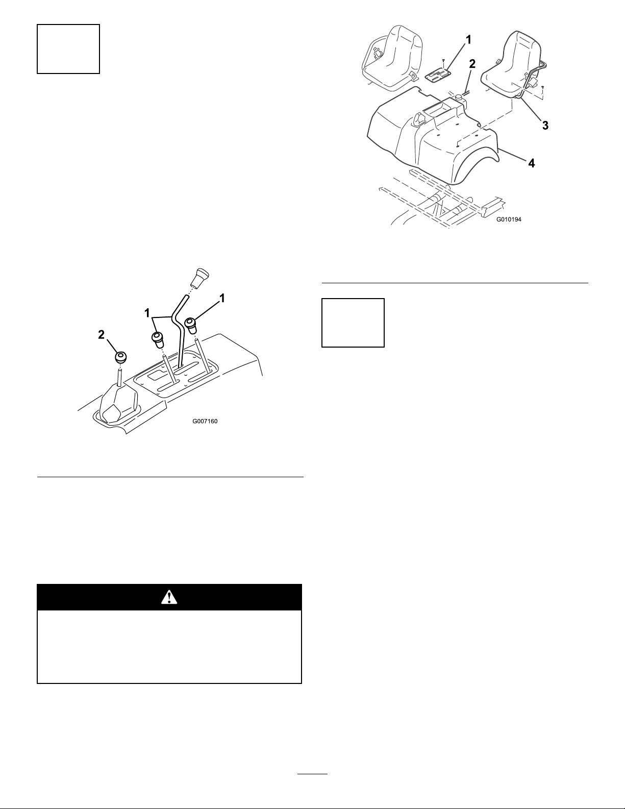
2.Unscrewandremoveallknobsfromconsolelevers
andfromthegearshiftlever(Figure2).
Figure2
1.Consolelevers2.Gearshiftlever
3.Remove(6)screwssecuringoutsideedgeofcenter
consolecoverplatetoframeandremovecoverplate
(Figure3).
4.Disconnectthereservoirhosefromtheradiatorand
plugorclampittoretaincoolant(Figure3).Remove
theoperatorshieldfromtheROPS.
Pressurizedhotcoolantescapingcancause
seriousburns.
Allowenginetocoolenoughtotouchbefore
removingoverowtubeorradiatorcap.
5.Removethecapscrewssecuringtheseatsandshroud
tomountingbrackets(Figure3).Removetheseats
andshroud.
Figure3
1.Consolecoverplate3.Seat
2.Reservoirhose4.Shroud
2
RemovingtheHood
NoPartsRequired
ForWorkman3000–4000series
vehicleswithserialnumbers240000001
andup
1.Removethe(6)screwsandnutssecuringthebumper
tothevehicleframeandremovethebumper.
2.Removethe(7)screwssecuringthefronthoodto
thevehicleframeandremovethehood.
ForWorkmanHD,HDXandHDX-D
vehicles
1.Positionthevehicleonalevelsurface,stopthe
engine,engagetheparkingbrakeandremovethe
keyfromtheignition.
2.Whilegraspingthehoodintheheadlightopenings,
liftuponthehoodtoreleasethelowermounting
tabsfromthebumperslots.
3.Pivotthebottomofthehoodupwarduntilthetop
mountingtabscanbepulledfromthedashslots.
4.Pivotthetopofthehoodforwardandunplugthe
wireconnectorsfromtheheadlights.
5.Removethehood.
7

3
InstalltheMainWireHarness
w/Relays
Partsneededforthisprocedure:
1MainWireHarnessw/Relays
7CableTie
2Screw,1/4x3/4inch
2Nut,1/4inch
1Fuse
ForWorkman3000–4000series
vehicleswithserialnumbers240000001
andup
1.Insertendofwireharness,withmaleandfemale
spadeterminalsonit,upthroughopeninginvehicle
oorboard,towarddashpanel,followingvehicle
wireharness.Secureharnesstovehiclewireharness
with(2)cableties.
2.Locatered/blackwireconnectedto"I"terminalof
ignitionswitch.Removewirefrom“I”terminaland
plugintoappropriatewireharnessterminal.Plug
remainingharnessterminalontoignitionswitch“I”
terminal.
3.Removefastenerssecuringwireharnesscoverto
undersideofvehicleoorandremovecover.
4.Routewireharnessrearwardtoconsolearea.
Harnessmustnotinterferewithanyhot(exhaust)or
movingparts.Securetheharnesswithcableties.
5.Mounttherelaystotheleftframechannelwith
2(1/4x3/4inch)screwsand(1/4inch)nuts
(Figure4).
Note:Ifthevehicleisequippedwithhighow
hydraulics,locateanothersuitablemountinglocation.
Figure4
1.Relays
ForWorkmanHD,HDXandHDX-D
vehicles
1.Insertendofwireharness,withmaleandfemale
spadeterminalsonit,upthroughopeninginvehicle
oorboard.
2.Locateanemptyslotinthefuseblock.Ifnoempty
slotisavailable,anadditionalfuseblock(Toropart
no.92–2641)willhavetobeadded.
3.Inserttheincludedfuseintotheemptyfuseblock
slotandconnectthewireharnessspadeterminalto
thecorrespondingspadeterminalonthefuseblock.
4.Removefastenerssecuringwireharnesscoverto
undersideofvehicleoorandremovecover.
5.Routewireharnessrearwardtoconsolearea.
Harnessmustnotinterferewithanyhot(exhaust)or
movingparts.Securetheharnesswithcableties.
6.Mounttherelaystotheleftframechannelwith
2(1/4x3/4inch)screwsand(1/4inch)nuts
(Figure4).
Note:Ifthevehicleisequippedwithhighow
hydraulics,locateanothersuitablemountinglocation.
8

4
MounttheParkingBrake
Switch
Partsneededforthisprocedure:
1Parkingbrakeswitch
2Screws
Procedure
1.Mounttheparkingbrakeswitchtotheparkingbrake
mountwithtwoscrewsasshowninFigure5.
Figure5
1.Switch
2.Plugswitchwireconnectorintoliftwireconnector
harness.
3.Removetheloopbackconnectorfromthevehicle
wireharnesslabeled1/3lift.Connecttheliftwire
harnesstothevehiclewireharenss.
5
MountRearLevelSwitch
Partsneededforthisprocedure:
1Rearlevelswitchbracket
1Rearlevelswitchw/harness
ForWorkman3000–4000series
vehicleswithserialnumbers240000001
andup
1.Removelocknutssecuringhitchplatetorearaxle
(Figure6).Usingtheuppersetofmountingholes,
looselymountthelevelswitchbrackettorearaxle
withlocknutsremoved.
Figure6
1.Hitchplate3.Switchharness
2.Levelswitchbracket
2.Routeswitchharnessforward,alongdifferential
lockcabletoleftsideofmachine.Harnessmustnot
interferewithanyhot(exhaust)ormovingparts.
Secureharnesstodifferentiallockcablewithcable
ties.
ForWorkmanHD,HDXandHDX-D
vehicles
1.Removecapscrewssecuringhitchplatetorearaxle
(Figure7).Usingthelowersetofmountingholes,
looselymount2washersandlevelswitchbracketto
rearaxlewithcapscrewsremoved.Thewashersare
tobepositionedbetweenthehitchplateandaxle.
9
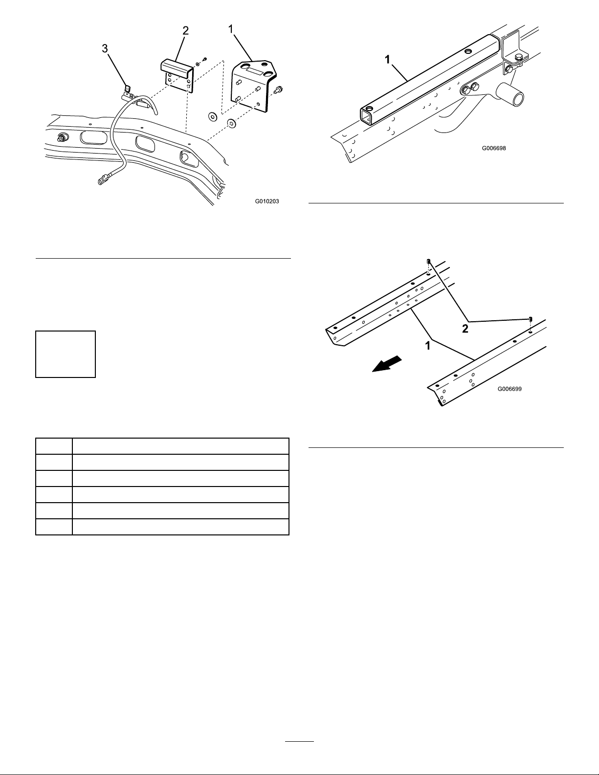
Figure7
1.Hitchplate3.Switchharness
2.Levelswitchbracket
2.Routeswitchharnessforward,alongshiftcableto
leftsideofmachine.Harnessmustnotinterferewith
anyhot(exhaust)ormovingparts.Secureharnessto
shiftcablewithcableties.
6
MountLiftontoVehicleFrame
Partsneededforthisprocedure:
2ReinforcingPlate
2Spacertube
2FlangeHD.Capscrew,3/8-16x3inch
2FlangeHD.Capscrew,3/8-16x3–1/2inch
4FlangeHD.Capscrew,3/8-16x1inch
4Flangenut,3/8-16
ForWorkman3000–4000series
vehicleswithserialnumbers240000001
andup
Note:Toinstalltheplatformliftinthemidposition,
theMidMountKitforthePlatformLift,PartNo.
93–3741mustbepurchasedandinstalled.
1.Removeanyaccessoriesmountedtotopofframein
forwardpositionsuchasa1/3bed,powerplatform,
H.D.HitchFrameextensiontubes(Figure8),etc.
Figure8
1.Hitchframeextensiontube
2.Locateandremovethethreadedinsertfromthe
mountingholeinleftandrightvehicleframe
channels,asshowninFigure9.
Figure9
1.Vehicleframechannel2.Threadedinsert
Note:Topreventliftscissorarmsfromexpanding,
pickuptheplatformliftfromthebottomwhen
positioningonframe.
3.Positionliftontoframealigningmountingholeswith
holesinframe(Figure10).
10

Figure10
1.Lift2.Reinforcingplate
4.Mounteachsideoflifttoframechannelswith
areinforcingplateand(2)3/8-16x1inchlarge
angeheadcapscrewsandangenuts(Figure10).
Reinforcingplatestobeusedinrearmountingholes
only.
ForWorkmanHD,HDXandHDX-D
vehicles
Note:Toinstalltheplatformliftinthemidposition,
theMidMountKitforthePlatformLift,PartNo.
93–3741mustbepurchasedandinstalled.
1.Removeanyaccessoriesmountedtotopofframein
forwardpositionsuchasa1/3bed,powerplatform,
H.D.HitchFrameextensiontubes,etc.(Figure8),
Figure11
1.Hitchframeextensiontube
2.Locateandremovethethreadedinsertfromthe
mountingholeinleftandrightvehicleframe
channels,asshowninFigure9.
Figure12
1.Vehicleframechannel2.Threadedinsert
3.Positionaspacertubeontoeachframechannel
aligningmountingholeswithholesinframe
(Figure13).
Figure13
1.Spacertube3.Reinforcingplate
2.Lift
Note:Topreventliftscissorarmsfromexpanding,
pickuptheplatformliftfromthebottomwhen
positioningonframe.
4.Positionliftontospacertubesaligningmounting
holeswithholesintubes(Figure13).
5.Mounttherearofeachsideoflifttotheframe
channelswithareinforcingplate,(2)3/8-16x3–1/2
11
inchangeheadcapscrewsandangenuts.Usethe
(2)3/8-16x3inchangeheadcapscrewsinfront
mountingholes(Figure13).
7
ConnectWires
NoPartsRequired
Procedure
1.Plugrearharnessintoconnectorfromfrontharness.
2.Plugtheconnectorfromtheliftintotheliftharness.
3.Connectgroundwirefromlifttoengineground.
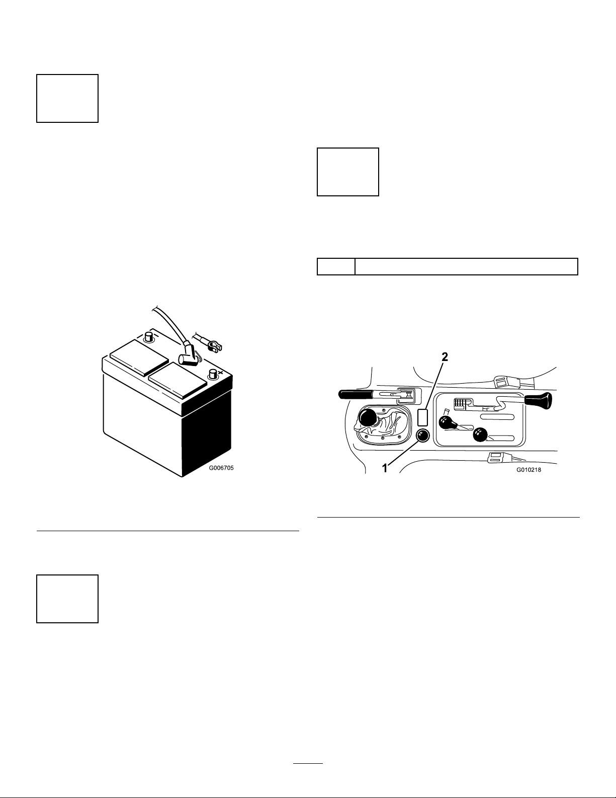
4.Removenutfrompositivebatteryclamp,insert
positivewirefromliftontocableclampscrewand
looselysecurewithnut.
G006705
Figure14
1.Positiveliftwire2.Positivebatterycable
clamp
5.Makesurewiringisclearofallhotorrotatingparts.
Securewithcabletiesasrequired.
8
ReinstallHoodandReconnect
Battery
NoPartsRequired
Procedure
1.Reinstallhoodtoframe.
2.Reinstallshroud,seats,seatframeandconsolecover
plate,ifapplicable.
3.Reinstalloverowtubetoradiator.Checkcoolant
levelandreplenish,ifrequired.
4.Reinstallpositivebatterycabletobattery.
5.Sliderubberbootoverpositiveterminaltoprevent
possibleshort-outfromoccurring.
9
MountCircularBubbleLevel
Partsneededforthisprocedure:
1CircularBubbleLevel
Procedure
Afxcircularleveltotopofconsolecoverpositioning
asshowninFigure15.
G010218
1
2
Figure15
1.Circularlevel2.Operationdecal
12
10
InstallDecals
Partsneededforthisprocedure:
1OperationDecal
2NoStepDecal
ForWorkman3000–4000series
vehicleswithserialnumbers240000001
andup
1.Afxoperationdecaltotopofconsolecover
positioningasshowninFigure15.
2.Afxa"NoStep"decaltotopofeachfueltank
mountingstrap,asshowninFigure16.
Figure16
1.No—Stepdecal
ForWorkmanHD,HDXandHDX-D
vehicles
1.Afxoperationdecaltotopofconsolecover
positioningasshowninFigure15.
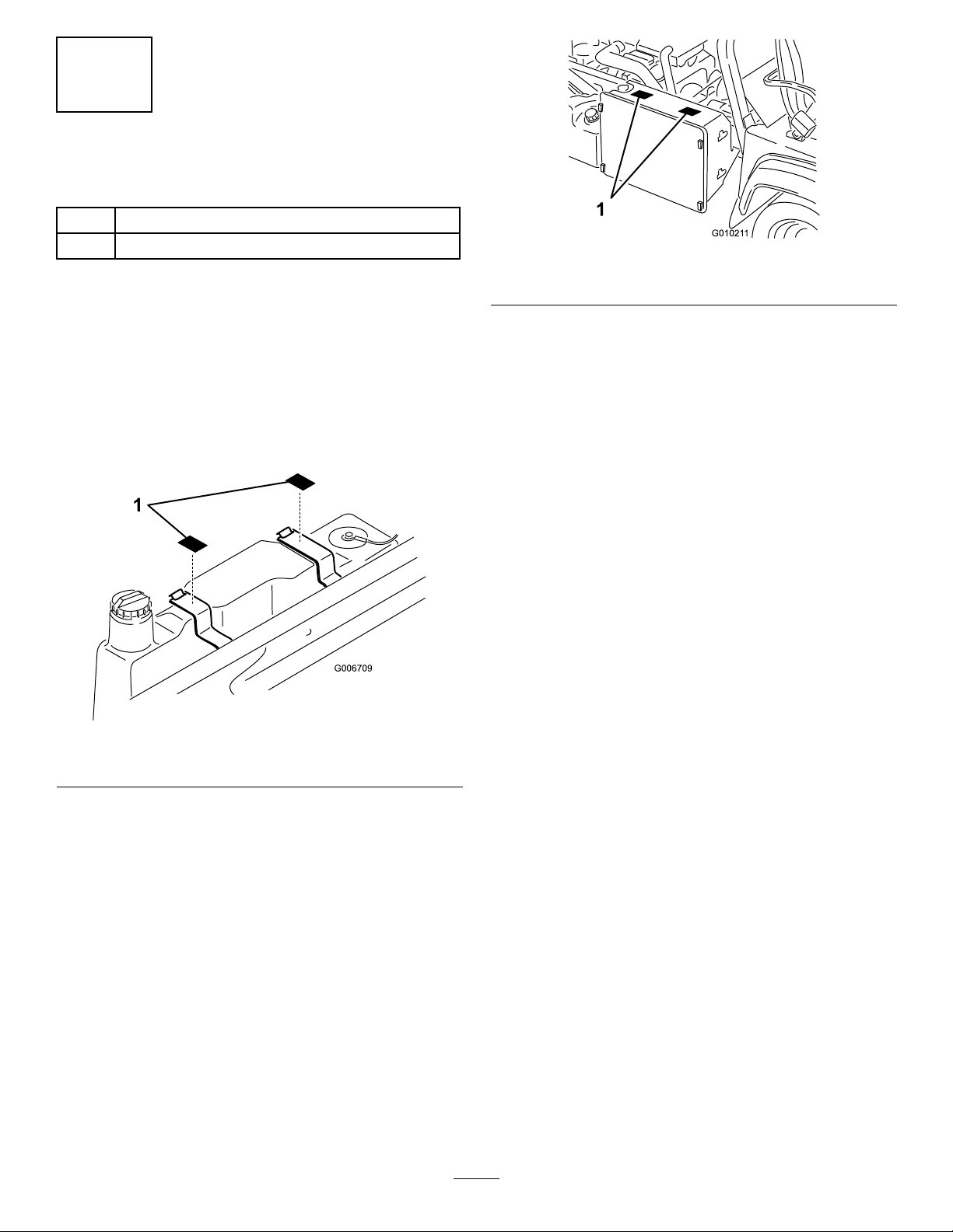
2.Afxthe"NoStep"decalstotopofradiator,as
showninFigure17.
G01021 1
1
Figure17
1.No—Stepdecal
13

ProductOverview
Controls
UpButton
Press"UP"buttontoraiselift(Figure18).
DownButton
Press"DOWN"buttontolowerlift(Figure18).
KeySwitch
Rotatekeyswitchtoauthorizeuseoflift.Removekey
fromliftpendantcontrolswitchtopreventoperation
whenunattended.(Figure18).
Figure18
1.Pendantcontrol3.DOWNbutton
2.UPbutton4.Keyswitch
EmergencyLoweringValveKnob
Pushinredknobonsolenoidvalveandrotate180
degreescounter-clockwisetoactivateemergency
loweringvalve.Tostopliftandreturntonormal
operation,pushbuttonin,rotate180degreesclockwise
andrelease(Figure19).
Figure19
1.Emergencyloweringvalveknob
14

Operation
CheckOilLevel
TheliftreservoirislledatthefactorywithDTE13
hydraulicoil.Checklevelbeforeliftisrstoperatedand
every8hoursordaily,thereafter.Capacityofsystem
is1.5qt.
1.Positionthevehicleonalevelsurface.
2.Raiseliftandinstallsafetyblocks.Refertothe
InstallingSafetyBlockssectionandtheOperation
chapter.
Note:Ifliftcannotberaised,duetolackofoilin
reservoir,itmayberaisedwithahoistandsafety
blocksinstalled,toexposereservoirbreathercap.
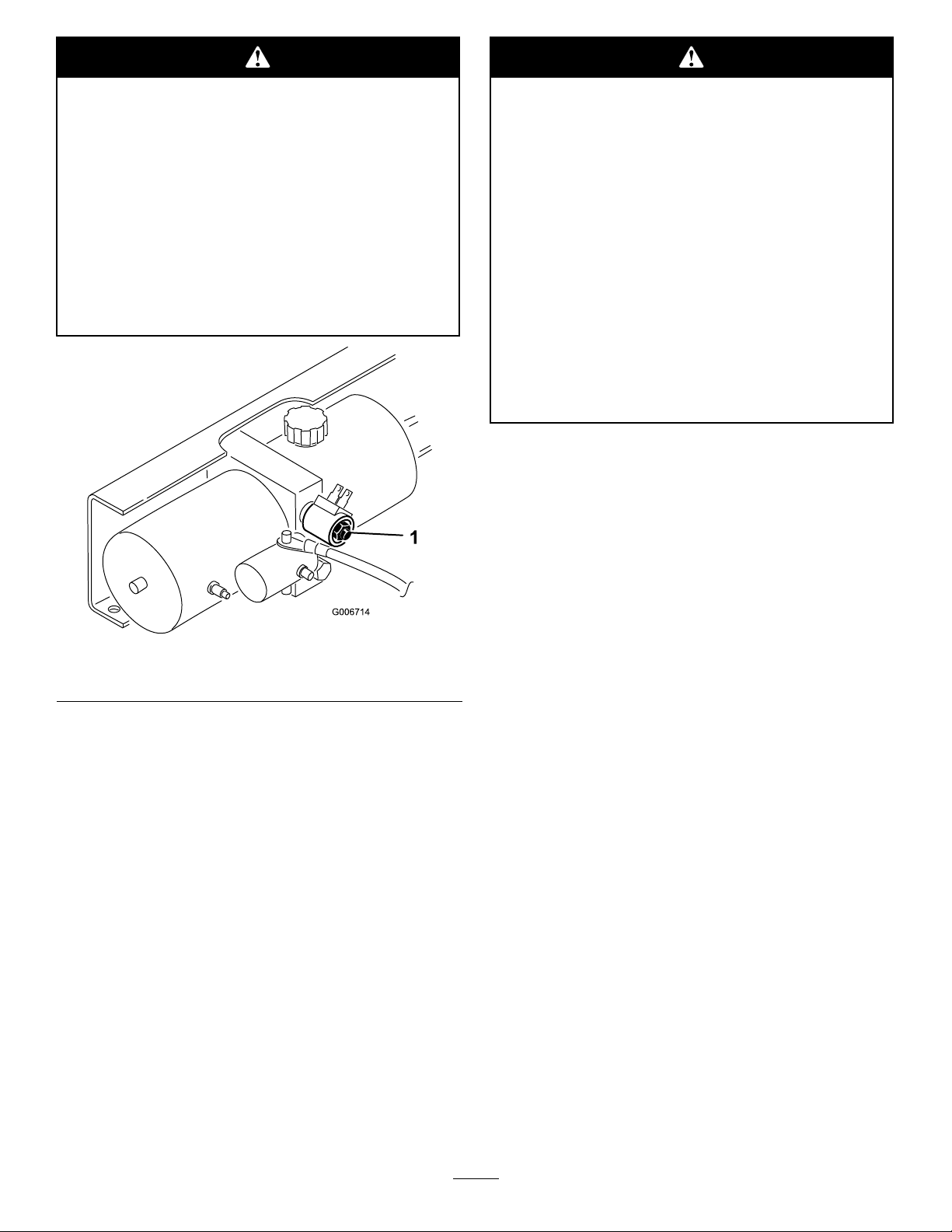
3.Cleanareaaroundreservoirbreathercap(Figure20).
Figure20
1.Reservoircap
4.Unscrewbreathercapfromtopofreservoir.
5.Insertacleanrodorstickintoreservoirandcheck
uidlevel.Fluidshouldbewithin2inchesfromtop
ofreservoir.Iflevelislow ,addenoughDTE13
hydraulicoiltoachievetheproperlevel.DONOT
OVERFILL.
Note:IfDTE13hydraulicoilisnotavailable,
DTE24orDextronllATFmaybesubstituted.
Fluidsmaybemixed,afterinitialllofreservoir.
Note:AlwaysuseDTE13,DTE24,orequivalent
ISOViscosityGrade32oilswhenreservoirmustbe
completelyrelledorifcoldweatherisexpected.
Theuseofotheruidsmayinhibittheoperation
ofthelift.
CheckTirePressure
Checktirepressureevery8hoursordailytoassure
properlevels.
Refertothevehicleoperator’smanualforpropertire
inationspecication.
InstallingSafetyBlocks
1.Positionthevehicleonalevelsurface.
2.Setparkingbrakeandchockwheels.
3.Rotatevehiclekeyswitchto"Off"position.
4.Whilestandingnexttomachine,grasppendant
controlandrotateliftkeyswitchto"On"position.
Checkoverheadclearanceandforanyobstructions.
5.Press"UP"buttontoraiselifthighenoughtoinstall
safetyblocks.Standclearofscissorarmswhile
platformismoving.
Contactwithmovingscissorarmscancause
personalinjury.
•Standclearofscissorarmswhileplatform
ismoving.
•Makesureareaisclearofbystandersbefore
loweringplatform.
•Neverworkunderraisedplatformwithout
liftsafetyblocksinstalled.
•Alwaysremovekeyfromliftcontrolbox
whenplatformisnotinuse.
6.Removeretainingpinssecuringsafetyblockstoside
ofliftframe(Figure21).
Figure21
1.Safetyblock2.Retainingpin
15
7.Rotatesafetyblocks90degreesinchanneland
securetoendsofliftframewithretainingpins
(Figure22).
Figure22
Platformliftcancrushandcausepersonal
injury.
•Neverworkunderraisedplatformwithout
liftsafetyblocksinstalled.
•Neverusesafetyblockstosupportaload
onlift.
8.Press"DOWN"buttononpendantcontroland
lowerliftuntilrollersgentlycontactsafetyblocks.
9.Toremovesafetyblocks:
•Raiseliftslightly.
•Removeretainingpins.
•Returnsafetyblockstostorageposition.
•Securewithretainingpins.
OperatingtheLift
The1/3platformliftisdesignedtobeusedonlywith
aWorkmanVehicleandmustbemountedwiththe
wiringharness,level,decals,switchesandallinterlock
switchesinstalled.
Improperoperationofplatformliftmaycause
seriouspersonalinjuryordeath.Toreducerisk
tooperatorandbystanders:
•Readandunderstandallsafetyinstructions
inWorkmanandPlatformLiftOperator’s
Manualsandwarninglabels.
•Neveruseaplatformliftwithoutproper
trainingandauthorization.
Theelectricalcontrolsystemoftheliftrequiresthe
vehicletobeparkedonaslopeoflessthana5degree
angle,parkingbrakeengagedandthevehiclekeyinthe
“Off”positioninordertoactivatetheliftcircuit.
Operating
1.Setparkingbrakeandchockwheels.
2.Rotatevehiclekeyswitchto"Off"position.
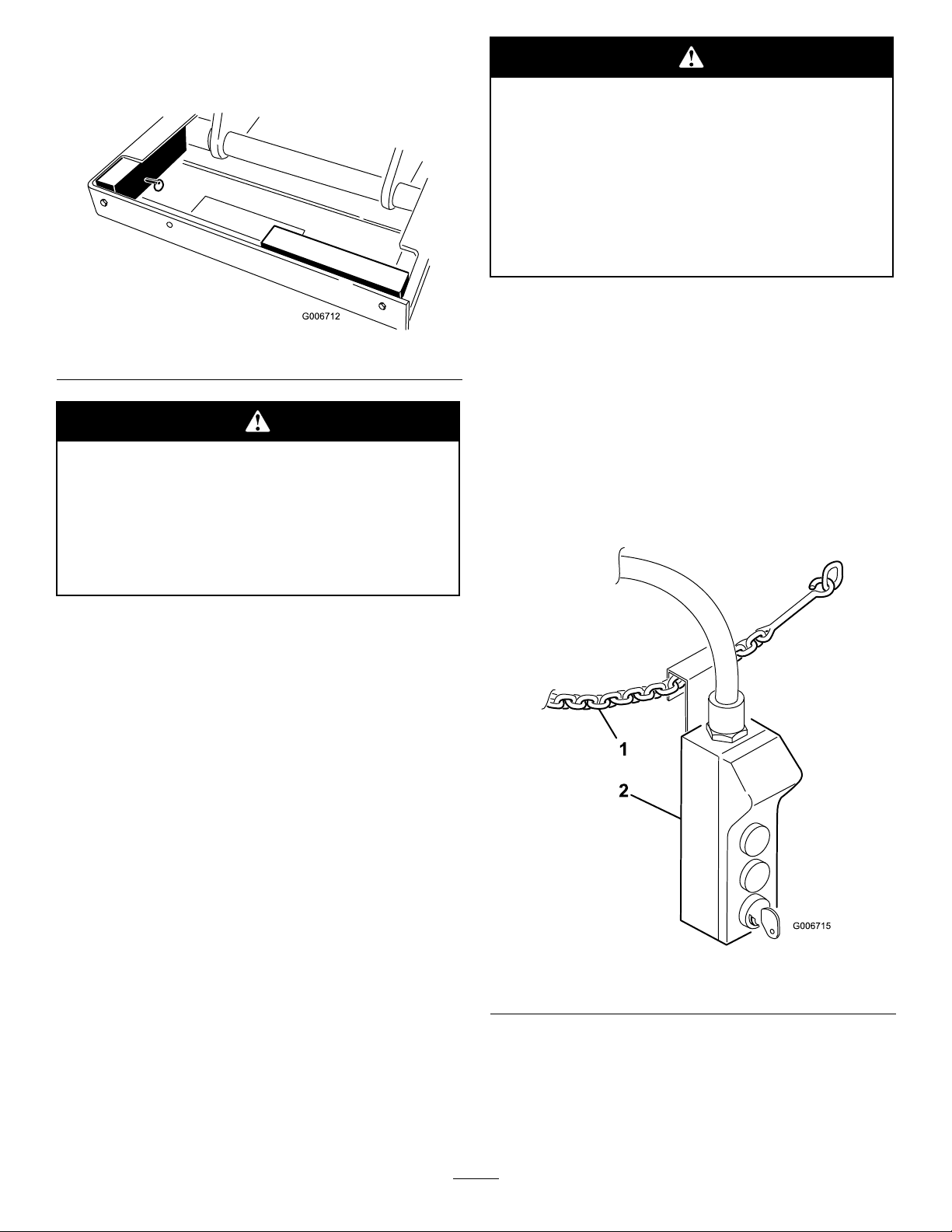
3.Climbintoplatformandsecuresafetychainsacross
entry(Figure23).
Figure23
1.Safetychain2.Pendantcontrol
4.Grasppendantcontrolandrotateliftkeyswitchto
"On"position.
5.Press"UP"buttontoraiselift;"DOWN"button
tolowerlift.
16

Operationofplatformliftwithoutparkingbrake
engagedcanresultintip-overandpersonal
injury.
•Alwaysapplyparkingbrakebeforeoperating
platformlift.Theuseofwheelchocksis
recommended.
•Donotreleaseparkingbrakewhileplatform
liftisraised.
•Donotraisetheplatformliftifthebubbleis
outsideoftheoperatingregiononthelevel
indicator.
Lossofcontrolortip-overwillresultifvehicle
ismovedwithplatforminraisedpositionand
maycauseseriouspersonalinjurytooperator
orbystanders.
•Nevermovevehiclewhileplatformisraised.
•Alwaysapplyparkingbrakebeforeraising
platform.Wheelchockuseisrecommended.
•Neverreleaseparkingbrakewhileplatform
israised.
•Checksafetyinterlocksbeforeeachuseof
platform.Seeoperator’smanualforsafety
interlockcheckinstructions.
•Neverbypasssafetyinterlocks.
•Neverallowridersonplatforminany
position.
Ifliftdoesnotoperate:
•Makesurevehiclekeyandliftkeyarein"Off"
position.
•Makesurevehicleisparkedonlessthana5
degreeangleslope.
•Makesurevehicleparkingbrakeis"On".
6.Whennishedwithworkoperation,lowerliftallthe
waydowntostopsandremovekeyfromliftpendant
controltopreventoperationwhenunattended.
Important:Ifenginekillswhenreleasing
parkingbrake,itmayindicatethatliftisnot
completelylowered.Vehiclecannotbedriven
withliftraisedatanyheight.
Contactbetweennon-insulatedplatformlift
andpowerlineswillcauseelectrocution.
•Electrocutionwillcauseseriouspersonal
injuryordeath.
•Neveruseplatformliftnearpowerlines.
•Neverallowplatformlifttotouchpower
lines.
•Ifpowerlinecontactoccurs:
–Lowerunitawayfromcontactifpossible.
–Donottouchpowerline.
–Nevertouchgroundwhiletouching
platformliftorpowerline.
–Jumpclearifnecessary,withouttouching
platformliftorpowerline.
•Ifoperatingplatformliftnearelectrical,high
pressureoranytypeofrotatingequipment:
–Alwaysdisconnectpowertothat
equipment.
–AlwaysuseOSHAapprovedlock-out
devices.
•Neverusetheplatformliftduringathunder
orlightningstorm.
Lowertheplatformliftandavoidopenareas
intheeventofthreateningweather.
EmergencyLowering
1.Reachintoaccessopeningonlytoactivate
emergencyloweringvalve.
2.Pushinredknobonsolenoidvalve(Figure24)and
rotate180degreescounter-clockwisetoactivate
emergencyloweringvalve.
17
Contactwithmovingscissorarmscancause
personalinjury.
•Standclearofscissorarmswhileplatform
ismoving.
•Makesureareaisclearofbystandersbefore
loweringplatform.
•Neverworkunderraisedplatformwithout
liftsafetyblocksinstalled.
•Alwaysremovekeyfromliftcontrolbox
whenplatformisnotinuse.
Figure24
1.Emergencyloweringvalveknob
3.Tostopliftandreturntonormaloperation,push
buttonin,rotate180degreesclockwiseandrelease.
Fallingorjumpingfromraisedplatformwill
causepersonalinjury.
•Securebothhandrailsnapchainsacross
openingbeforeraisingplatform.
•Neverpullonobjectswhilereachingfrom
raisedplatform.
•Neverreachoverhandrailsunlessbothfeet
areonplatformdeck.
•Neverstepabovelevelofplatformdeckor
useladders,steprisersorplatformrailsto
extendworkingheightofplatform.
•Ifyoumustexitraisedplatform,slowlyand
carefullyclimbdownoutsideofscissorarm
frame.
OperatingTips
Theelectricalsystem,batteryandhydraulicliftcylinder
arenotdesignedforcontinuoususe.Allowsome
time,approximately1-1/2to2minutes,betweenlift
operationstomaintainoperatingtemperatures.
Frequentusewithouttheenginerunningoridling,
betweenliftuse,maydischargethebattery.Ifengine
operationisnotpossibletokeepbatterycharged,it
maybenecessarytosupplementoperationwithanover
nightbatterycharger.
Checkthespecicgravityoftheuidinthebatteryto
assureitisfullycharged.RefertoBatteryCaresection.
18

Tip-overofWorkmanVehiclewhileplatformis
raisedwillresultinpersonalinjurytooperator
and/orbystanders.
•Alwaysparkvehicleonrm,levelsurface
beforeraisingplatform.
•Neverexceed5degreemaximumangleof
operation.
•Neverraiseplatformifbubblelevelindicator
isoutsiderecommendedoperatingrange.
•Neverraiseplatformifoneormorevehicle
tiresunderinated;checktirepressuredaily.
•Neverpullonobjectswhilereachingfrom
raisedplatform.
•Neveruseplatformforcarryingorlowering
treelimbs,branchesorheavyoruneven
loads.
•Neverexceedcapacityofplatformlift(one
personwithequipmentnottoexceed600
lbs.)
•Neverraiseplatformduringhighwindsor
threateningweather.
•Neverby-passsafetyinterlocks.
•Neverallowridersonplatforminany
position.
Note:Toprailofplatformliftishigherthanvehicle
ROPSsobealerttolowoverheadareaswhen
transporting(driving)vehicle.
Fallingobjectsandoverheadobstructionscan
causepersonalinjury.
•Alwayswearhardhatandeyeprotection
whileoperatingplatformorwhileinarea
belowplatform.
•Neverdroporthrowarticlesfromraised
platform.
•Whenraisingplatformbealertforoverhead
obstructionswhichcouldcauseeye,head
orcrushinginjuries.
19

Maintenance
CheckSafetyCircuits
Theelectricalsafetycircuitsoftheliftrequirethevehicle
tobeparkedonaslopeoflessthan5degrees,parking
braketobeengagedandtheignitionkeyoffinorder
toactivatetheliftcircuit.
Toverifyparkingbrakeswitch
operation:
1.Positionthevehicleonalevelsurface,setparking
brakeandchockwheels.
2.Rotatevehiclekeyswitchto"Off"position.While
standingnexttomachine,grasppendantcontroland
rotateliftkeyswitchto"On"position.Press"UP"
buttonandraiseliftafewinches.Releasebutton.
3.Releaseparkingbrakeandtrytoraiseliftagain.Lift
mustnotrise.Ifliftdoesnotraise,safetycircuitis
operatingcorrectlyandproceedtonextstep.Iflift
risesthereisamalfunctionintheelectricalcircuit
thatmustberepairedbeforeoperatinglift.
4.Withtheplatformpartiallyraisedandparkingbrake
released,trytostartengine.Ifenginedoesnot
startandremainrunning,safetycircuitisoperating
correctly.Lowerliftallthewayandproceedtonext
step.Ifenginestartsandremainsrunningthereis
amalfunctionintheelectricalcircuitthatmustbe
repairedbeforeoperatinglift.
Toverifyrearaxlelevelswitch
operation:
1.Positiononesideofvehicle(rearaxle)onaslope
greaterthan5degrees(oorjack,moundofmaterial
orsmallhill).
2.Setparkingbrakeandchockwheels.
3.Rotatevehiclekeyswitchto"Off"position.While
standingnexttomachine,grasppendantcontroland
rotateliftkeyswitchto"On"position.Press"UP"
buttonandtrytoraiselift.Ifliftdoesnotraise,
safetycircuitisoperatingcorrectly.Raiseopposite
sideofmachineandrepeatprocedure.Ifliftrises,
witheithersideofmachineinraisedposition,there
isamalfunctionintheelectricalcircuitthatmustbe
repairedbeforeoperatinglift.Lowerliftimmediately.
BatteryCare
1.Batteryelectrolytelevelmustbeproperlymaintained
andthetopofthebatterykeptclean.Ifthemachine
isstoredinalocationwheretemperaturesare
extremelyhigh,thebatterywillrundownmore
rapidlythanifthemachineisstoredinalocation
wheretemperaturesarecool.
2.Keeptopofbatterycleanbywashingperiodically
withabrushdippedinammoniaorbicarbonateof
sodasolution.Flushthetopsurfacewithwaterafter
cleaning.Donotremovethellcapwhilecleaning.
3.Batterycablesmustbetightonterminalstoprovide
goodelectricalcontact.
4.Ifcorrosionoccursatterminals,removebattery
cover,disconnectcables,negative(-)cablerstand
scrapeclampsandterminalsseparately.Reconnect
cables,positive(+)cablerstandcoatterminals
withpetroleumjelly.
5.Checktheelectrolytelevelevery50operatinghours
or,ifmachineisinstorage,every30days.
6.Maintaincelllevelwithdistilledordemineralized
water.Donotllcellsabovethebottomofthell
ringinsideeachcell.
7.Ifthemachinewillbestoredformorethan30
days,removethebatteryandchargeitfully.Either
storeitontheshelforonthemachine.Leavethe
cablesdisconnectedifstoredonthemachine.Store
thebatteryinacoolatmospheretoavoidquick
deteriorationofthechargeinthebattery.Toprevent
batteryfromfreezing,makesureitisfullycharged.
Thespecicgravityofafullychargedbatteryis
1.250.
Batteryelectrolytecontainssulfuricacidwhich
isadeadlypoisonanditcausessevereburns.
•Ifyoucarelesslydrinkelectrolyteyoucould
dieorifitgetsontoyourskinyouwillbe
burned.
•Donotdrinkelectrolyteandavoidcontact
withskin,eyesorclothing.
•Wearsafetyglassestoshieldyoureyesand
rubberglovestoprotectyourhands.
•Fillthebatterywherecleanwaterisalways
availableforushingtheskin.
•Followallinstructionsandcomplywithall
safetymessagesontheelectrolytecontainer.
20
Table of contents
Popular Lifting System manuals by other brands

R. Beck Maschinenbau
R. Beck Maschinenbau HS 600 operating manual

Ravaglioli
Ravaglioli KP 1396 E manual

Reechcraft
Reechcraft PowerLift PL50 Operators safety manual

AUTEC
AUTEC ALM-6040FL User & installation manual

Braun
Braun Millennium 2 AD NL Series Service manual

Condor
Condor GD-3500 User instruction manual


