Toro MMX-650E-S User manual
FormNo.3429-703RevA
MMX-650E-SandMMX-850E-S
MortarMixers
ModelNo.60212—SerialNo.404320000andUp
ModelNo.60218—SerialNo.404320000andUp
ModelNo.60219—SerialNo.404320000andUp
Registeratwww.Toro.com.
OriginalInstructions(EN)*3429-703*A
WARNING
CALIFORNIA
Proposition65Warning
Thepowercordonthisproductcontains
lead,achemicalknowntotheState
ofCaliforniatocausebirthdefects
orotherreproductiveharm.Wash
handsafterhandling.
Useofthisproductmaycauseexposure
tochemicalsknowntotheStateof
Californiatocausecancer,birthdefects,
orotherreproductiveharm.
Introduction
Thismachineisdesignedtomixmortar,plaster,
reproongmaterial,grout,andothersmall-grained
cementproducts.Avehicleequippedwithan
appropriatepintlehitchorballhitchcantowthe
machine..
Readthisinformationcarefullytolearnhowtooperate
andmaintainyourproductproperlyandtoavoid
injuryandproductdamage.Youareresponsiblefor
operatingtheproductproperlyandsafely.
YoumaycontactT orodirectlyatwww.T oro.com
forproductsafetyandoperationtrainingmaterials,
accessoryinformation,helpndingadealer,orto
registeryourproduct.
Wheneveryouneedservice,genuineToroparts,or
additionalinformation,contactanAuthorizedService
DealerorToroCustomerServiceandhavethemodel
andserialnumbersofyourproductready.Writethe
numbersinthespaceprovided.
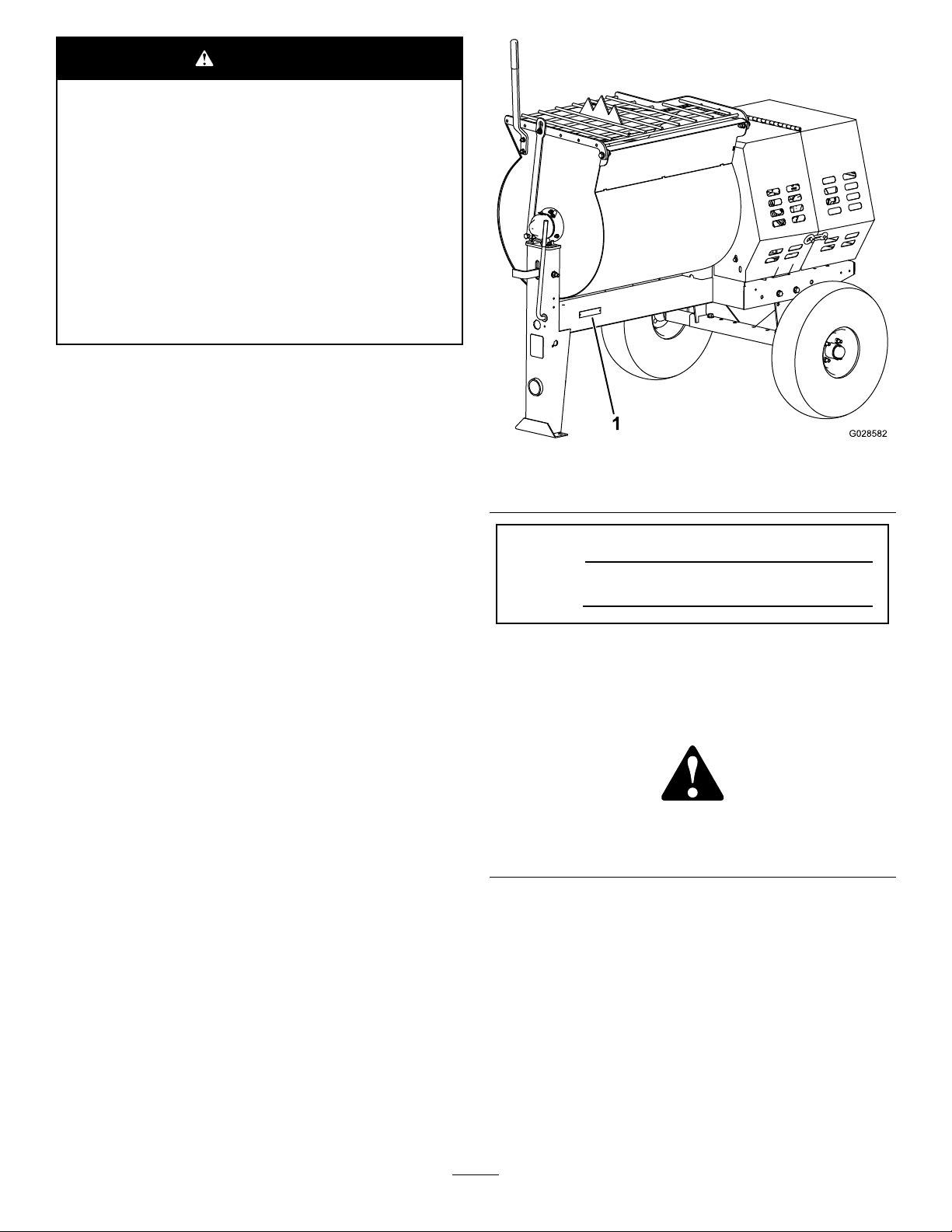
g028582
Figure1
1.Modelandserialnumberlocation
ModelNo.
SerialNo.
Thismanualidentiespotentialhazardsandhas
safetymessagesidentiedbythesafetyalertsymbol
(Figure2),whichsignalsahazardthatmaycause
seriousinjuryordeathifyoudonotfollowthe
recommendedprecautions.
g000502
Figure2
1.Safetyalertsymbol
Thismanualuses2wordstohighlightinformation.
Importantcallsattentiontospecialmechanical
informationandNoteemphasizesgeneralinformation
worthyofspecialattention.
TheDOTtireinformationislocatedonthesideof
eachtire.Thisinformationgivesloadandspeed
ratings.Replacementtiresshouldhavethesameor
betterratings.
Note:Thevariousmachinesinthismanualhave
differentweights;refertoSpecications(page12)to
ensurethatthetiresonyourmachinemeetorexceed
theweightrequirementsofyourmachine.
©2018—TheToro®Company
8111LyndaleAvenueSouth
Bloomington,MN554202
Contactusatwww.Toro.com.
PrintedintheUSA
AllRightsReserved

Contents
Safety.......................................................................3
SafeOperatingPractices....................................3
SafetyandInstructionalDecals..........................7
Setup........................................................................8
1InstallingtheDumpHandle..............................8
2InstallingtheT owPole.....................................8
3InstallingtheSafetyChain...............................9
4AdjustingtheMixingPaddles.........................10
ProductOverview...................................................10
Controls............................................................11
Specications..................................................12
Operation................................................................14
PreparingtoT owtheMachine...........................14
ExtendingtheAxle............................................17
TowingtheMachine..........................................18
PreparingtoUsetheMachine...........................18
OpeningandClosingtheCowl..........................19
PoweringtheMachine......................................20
StartingandStoppingtheMotor........................21
ControllingthePaddles.....................................21
MixingtheMaterial...........................................22
UsingtheDrum.................................................24
Maintenance...........................................................25
RecommendedMaintenanceSchedule(s)...........25
Pre-MaintenanceProcedures..............................25
PreparingtheMachineforMaintenance............25
RemovingandInstallingtheDivider
Plate..............................................................25
Lubrication..........................................................26
LubricatingtheBearingsandSeals...................26
LubricatingtheMotorBearings.........................27
LubricatingtheDriveChain...............................28
BeltMaintenance................................................28
ServicingtheBelts............................................28
ReplacingtheBelts...........................................29
AligningthePulleys..........................................31
DriveChainMaintenance.....................................32
CheckingandAdjustingtheDrive
Chain............................................................32
PaddleMaintenance............................................33
AdjustingthePaddles.......................................33
Cleaning..............................................................35
CleaningtheMachine.......................................35
Storage...................................................................35
StoringtheMachine..........................................35
Troubleshooting......................................................36
Schematics.............................................................37
Safety
Improperlyusingormaintainingthemachinecan
resultininjury.Toreducethepotentialforinjury,
complywiththesesafetyinstructionsandalways
payattentiontothesafetyalertsymbol,which
means:Caution,Warning,orDanger—personal
safetyinstruction.Failuretocomplywiththe
instructionmayresultinpersonalinjuryordeath.
SafeOperatingPractices
Thisproductiscapableofamputatinghands.Always
followallsafetyinstructionstoavoidseriousinjuryor
death.
WARNING
Machiningorhandlingstone,masonry,
concrete,metal,andothermaterialscan
generatedust,mists,andfumescontaining
chemicals,suchassilica,knowntocause
seriousorfatalinjuryorillness,suchas
respiratorydisease,silicosis,cancer,birth
defects,orotherreproductiveharm.
•Controldust,mist,andfumesatthesource
wherepossible.Watershouldbeusedfor
dustsuppressionwhenfeasible.
•Usegoodworkpracticesandfollowthe
recommendationsofthemanufactureror
suppliers,OSHA,andotheroccupational
andtradeassociations.
•Alwaysfollowrespiratoryprecautions.
•Whenthehazardsfrominhalationcannot
beeliminated,theoperatorandany
bystandersshouldweararespirator
approvedbyOSHAforthematerialbeing
handled.
Training
•ReadtheOperator'sManualandothertraining
material.Iftheoperator(s)ormechanic(s)cannot
readorunderstandtheinformation,itisthe
owner'sresponsibilitytoexplainthismaterialto
them.
•Becomefamiliarwiththesafeoperationofthe
equipment,operatorcontrols,andsafetysigns.
•Alloperatorsandmechanicsshouldbetrained.
Theownerisresponsiblefortrainingtheusers.
3

•Neverletchildrenoruntrainedpeopleoperateor
servicetheequipment.Localregulationsmay
restricttheageoftheoperator.
•Theowner/usercanpreventandisresponsible
foraccidentsorinjuriestopeopleordamageto
property.
Towing
Checkwithyourlocalcountyorstatetowingsafety
regulationsbeforetowingthemachine.
•Inordertoreducethepossibilityofanaccident
whiletransportingthemachineonpublicroads,
makesurethetowingvehicleismechanically
soundandingoodoperatingcondition.
•Turnoffthemotorbeforetransportingthemachine.
•Whentowingwithaballhitch,ensurethattheball
hitchyouareusingisthepropersizeforthehitch
coupleronthemachine.
•Whentowingwithapintlehitch,ensurethatthe
eyeofthetowpoleisthecorrectdimensionfor
thepintlehook.
•Inspectthehitchandcouplingforwear.Nevertow
themachinewithdamagedordefectivehitches,
couplings,chains,orothercomponents.
•Checkthetireairpressureonthetowingvehicle
andthemachine.
•Checkthetiretreadandsidewallfordamageand
wear.
•Properlyattachthesafetychainstothetowing
vehicle.
•Ensurethatthedirectionalandbrakelightsare
workingproperly(ifthemachineisequippedwith
thelightkit).
•Ensurethatthedirectional,backup,andbrake
lightsofthetowvehicleareworkingproperly.
•Beforetowing,checktomakecertainyour
machineiscorrectlyandsecurelyattachedtothe
towingvehicle.
•Ensurethatthesafetychainsareproperlysecured
tothevehicle,andleaveenoughslackforturning.
•Donotcarryanymaterialinthemachinewhen
towing.
•Avoidsuddenstopsandstarts.Thiscancause
skidding,orjackkning.Smooth,gradualstarts
andstopswillimprovetowing.
•Avoidsharpturnstopreventrolling.Towonlywith
avehiclethathasahitchdesignedfortowing.Do
notattachtowedequipmentexceptatthehitch
point.
•Donottowthemachinefasterthan88km/h(55
mph).
•Usecautionwhenbackingup;useaspotter
outsidethevehicletoguideyou.
•Donotallowanyonetositorrideonthemachine.
Preparation
Becomefamiliarwiththesafeoperationofthe
equipment,operatorcontrols,andsafetysigns.
4

•Useonlyaccessoriesandattachmentsapproved
bythemanufacturer.
•Wearpersonalprotectiveequipmentand
appropriateclothingincluding:
–Hardhat
–Respiratorordustmask
–Faceshield
–Safetyglasses
–Hearingprotection
–Safetyshoes
–Longpants
–Shirtwithlongsleevesthataretightatthe
wrists
–Tight-ttinggloveswithoutdrawstringsorloose
cuffs
•Securelonghair,looseclothing,orjewelrythat
maygettangledinmovingparts.
•Operatingtheequipmentsafelyrequiresthefull
attentionoftheoperator.Donotwearradioor
musicheadphoneswhileoperatingthemachine.
•Ensurethatthemachineisonalevelsurface
beforeoperatingthemachine.
•Chockthetiresofthemachinetoprevent
unintendedmovement.
•Beforeeveryuse:
–Inspectthecoupler,ball,andhitch.
–Ensurethatalllightsarefunctioningproperly(if
themachineisequippedwithalightkit).
–Ensurethatthetiresareproperlyinatedas
recommended.
–Ensurethatthelugnutsaretightandtorqued
properly.
–Ensurethatthemachineisproperlysecured.
Operation
•Neverrunthemachineinapoorlyventilated
orenclosedareawithoutproperrespiratory
protection.Dustfrommaterialsbeingmixedcan
beveryharmfultooperatorsandbystanders.
•Onlyoperatethemachineingoodlighting
conditions.
•Beforestartingthemachine,makesurethatthere
arenopersonsorobstaclesnearorunderthe
machine.
•Neverleavearunningmachineunattended.
Alwaysstopthemotorandverifythatallmoving
partshavestopped.
•Chockthetireswhenusingthemachine.
•Whennotusingthemachine,chockthetiresor
keepitattachedtothetowvehicle.
•Keephandsawayfromanymovingparts.Keep
feetawayfromthetiresandthefrontpost.
•Donotoperatethemachineoutdoorsintherain.
•Donotoperatethemachineundertheinuence
ofalcoholordrugs.
•Ensurethattheareaisclearofotherpeopleor
petsbeforeoperatingthemachine.Stopthe
machineifanyoneentersthearea.
•Neverplaceyourhandsoranysolidobjectintothe
drumwhenthemachineisinoperation.
•Donottouchpartswhichmaybehotfrom
operation.Allowthemtocoolbeforeattemptingto
maintain,adjust,orservicethemachine.
•Nevermovethemachinewhilethemotoris
running.
•Keepthecowlclosedandlatchedduringoperation.
•Ensurethatalltheguardsandshieldsaresecurely
inplacebeforeoperatingthemachine.
•EnsurethattheON/OFFswitchisintheOFF
positionbeforeconnectingthemachinetothe
electricalsource.
•Ifthemixingpaddlesstrikeaforeignobjectorif
themachineshouldstartmakinganunusualnoise
orvibration,stopthemotorandemptythedrum.
Waitforallmovingpartstocometoacomplete
stopandcool.Vibrationisgenerallyawarningof
trouble.Inspectforcloggingordamage.Clean
andrepairand/orreplacedamagedparts.
•Lightningcancausesevereinjuryordeath.Ifyou
seelightningorhearthunderinthearea,donot
operatethemachine;seekshelter.
5

MaintenanceandStorage
•Beforeperformingmaintenance,dothefollowing:
–Parkthemachineonlevelground.
–Stopthemotor.Waitforallmovementtostop
beforeadjusting,cleaning,orrepairing.
–Letthemotorcoolbeforeperforming
maintenanceorstoringthemachine.
–Unplugthemachinebeforemakinganyrepairs.
•Neverlubricate,service,repair,oradjustthe
machinewhileitisrunning.
•Keepequipmentmaterialsclearfromthemotor.
•Neverallowuntrainedpersonneltoservicethe
machine.
•Keephands,feet,andclothingawayfrommoving
parts.Ifpossible,donotmakeadjustmentswith
themotorrunning.
•Keepallpartsingoodworkingconditionandall
hardwaretightened.Replaceallwornordamaged
decals.
•Removeanybuildupofgrease,oil,ordebrisfrom
themachine.
•Donotmodifytheelectricalconnectorsorwiring.
•Donotconnectthegroundcircuitofthemachine
totheenergizedcircuitoftheelectricalsource.
•Donottamperwithsafetydevices.
•Chockthetireswhenstoringthemachine.
•Keepallnuts,bolts,screws,andhoseclamps
securelytightened.Keepequipmentingood
condition.
•Toensureoptimumperformanceandcontinued
safetycerticationofthemachine,useonly
genuineTororeplacementpartsandaccessories.
Replacementpartsandaccessoriesmadeby
othermanufacturerscouldbedangerous,and
suchusecouldvoidtheproductwarranty..
6

SafetyandInstructionalDecals
Safetydecalsandinstructionsareeasilyvisibletotheoperatorandarelocatednearanyarea
ofpotentialdanger.Replaceanydecalthatisdamagedorlost.
decal125-8175
125–8175
1.ReadtheOperator’sManualforinformationongreasing
themachine.
decal125-8216
125–8216
1.ReadtheOperator’s
Manualforinformationon
howtotowthemachine.
2.Warning—limittowing
speedtolessthan55mph
/88km/h.
decal133-8062
133-8062
decal127-1652
127–1652
1.Warning—readthe
Operator’sManual.
3.Entanglementhazardat
paddles—stopthemotor
andwaitforallmoving
partstostopbefore
servicingthemachine.
2.Handandarm
entanglementatthe
beltdrive;crushinghazard
ofhand;entanglement
hazardofhandatthe
shaft—keephandsaway
frommovingparts;keep
allguardsandsafetiesin
place.
4.Shockhazard—makesure
themachineisgrounded
beforeoperation.
7
Setup
LooseParts
Usethechartbelowtoverifythatallpartshavebeenshipped.
ProcedureDescriptionQty.Use
Dumphandle1
Bolt2
1Nut2
Installthedumphandle.
2Towpolekit(soldseparately)1Installthetowpole.
Safetychain(soldwithoptionaltowpole
kit)1
3Connectinglink(soldwithoptionaltow
polekit)2
Installthesafetychain.
4Nopartsrequired–Adjustingthemixingpaddles.
1
InstallingtheDumpHandle
Partsneededforthisprocedure:
1Dumphandle
2Bolt
2Nut
InstallingtheDumpHandletothe
Drum
1.Cutthecabletiestoremovethedumphandle
fromtheundersideofthegrate.
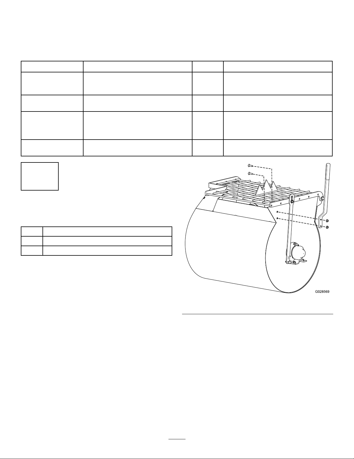
2.Positionthedumphandlesothattheboltholes
alignwiththeboltholesinthedrum(Figure3).
g028569
Figure3
3.Insert1carriageboltintothesquarebolthole
andslidethecorrespondingholeofthedrum
handleoverit(Figure3).
4.Installanutontothebolt,andtightenit.
5.Repeatthepreviousstepsfortheremaining
carriagebolt.
8
2
InstallingtheTowPole
Partsneededforthisprocedure:
1Towpolekit(soldseparately)
InstallingtheTowPoletothe
Machine
Note:Thetowpoleispurchasedseparatelyand
includesthenutandboltneededforinstallation.
Themachinehasthefollowingtowpoleoptions:
HitchTypeLength
50mm(2inch)ball—stamped78.7cm(31inches)
50mm(2inch)ball—forged78.7cm(31inches)
Pintle78.7cm(31inches)
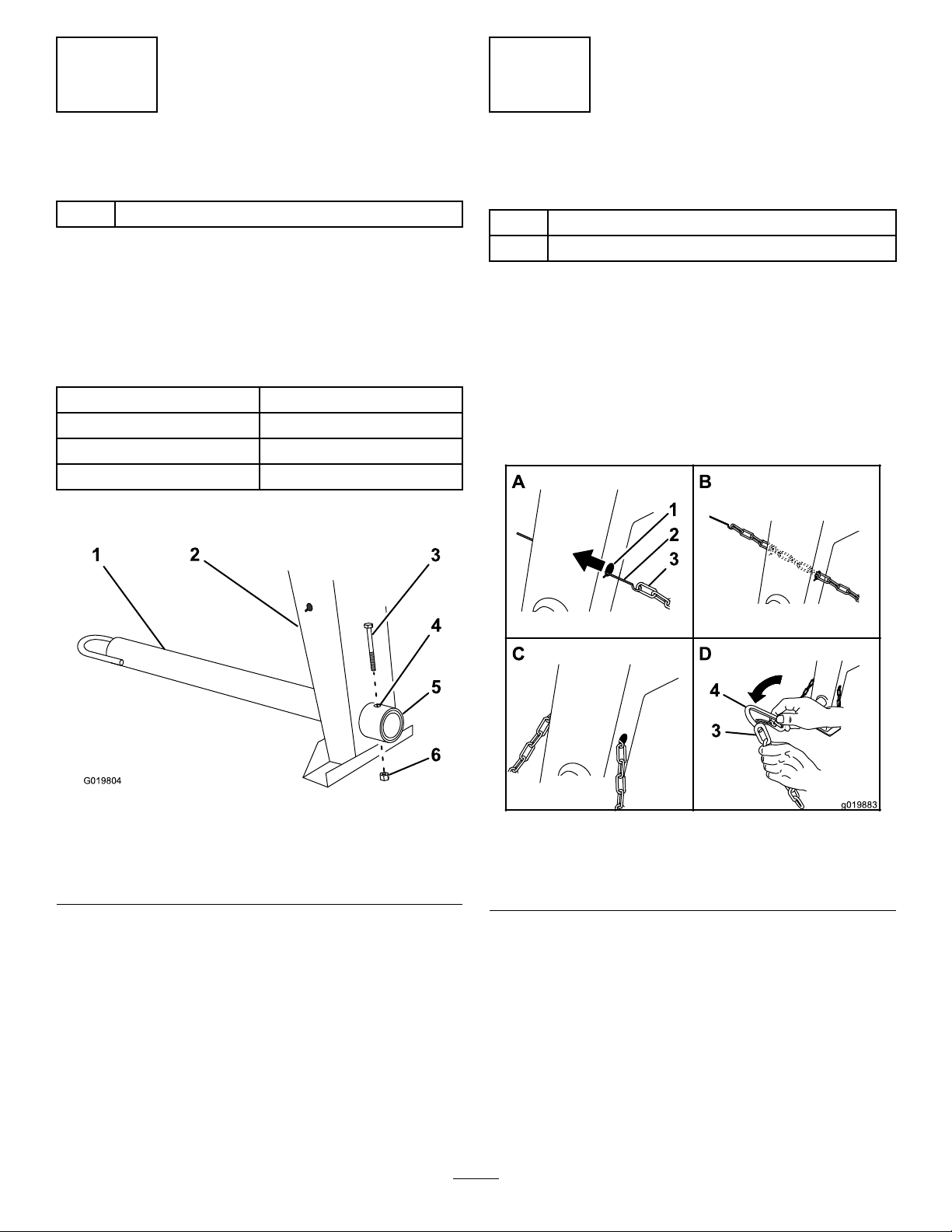
1.Removetheboltandnutfromthetowpole
(Figure4).
g019804
Figure4
1.Towpole4.Bolthole
2.Frontpost5.Frametting
3.Bolt6.Nut
2.Slidethetowpoleforwardandaligntheholein
thepolewiththeholeintheframetting(Figure
4).
3.Inserttheboltthroughtheholesinthettingand
thepole(Figure4).
4.Threadthenutontotheboltandtightenthem
untiltheyaretightagainsttheframetting
(Figure4).
Note:Iftheself-lockingnyloninsertinthe
locknutwearswithuse,replacethenutwitha
newGrade5orGrade8locknut.
3
InstallingtheSafetyChain
Partsneededforthisprocedure:
1Safetychain(soldwithoptionaltowpolekit)
2Connectinglink(soldwithoptionaltowpolekit)
InstallingtheSafetyChain
Note:Thesafetychainispartoftheoptionaltow
polekit.
1.Formahookontheendofabendablepiece
ofrodorstiffwire(notincluded),andinsertit
throughbothkeyholesinthefrontpostofthe
machine(Figure5A).
g019883
Figure5
1.Keyhole3.Safetychain
2.Rodorwire(notincluded)4.Connectinglink
2.Attachthesafetychaintothelengthofrodor
wire(Figure5A).
3.Pulltherod,orwire,andthesafetychain
throughbothkeyholes(Figure5B).
Note:Ensurethatapproximatelyequallengths
ofsafetychainextendfromeithersideofthe
frontpost.
9
InstallingtheConnectingLinks
Note:Theconnectinglinksarepartoftheoptional
towpolekit.
1.Aligntheconnectinglinktothelastlinkinone
endofthesafetychain(Figure5D).
2.Inserttheconnectinglinkthroughthechainlink
untiltheconnectinglinksnapsclosed.
3.Repeatsteps1and2toinstalltheother
connectinglinkintheotherendofthesafety
chain.
4
AdjustingtheMixing
Paddles
NoPartsRequired
Procedure
Ifthemixingpaddlesandwipersneedadjustment,
adjustthepaddlesandwipers;refertoAdjustingthe
Paddles(page33).
ProductOverview
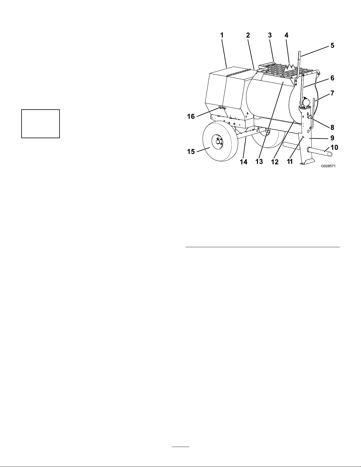
g028571
Figure6
1.Rearcowl7.Clutchlever13.Chute
2.Frontcowl8.Dumplatch14.Axle
3.Grate9.Frontpost15.Wheel
assembly
4.Bagsplitter10.Towpole16.Cowllatch
5.Dumphandle11.Safety-chain
keyhole
6.Grateliftarm12.Drum
10

Controls
Becomefamiliarwithallthecontrolsbeforeyoustart
themotorandoperatethemachine.
ClutchLever
Theclutchleverisusedtoengageanddisengage
motorpowertothepaddles.
g019875
Figure7
1.Clutchlever
DrumLatch
Thedrumlatchsecuresthedrumtothemixposition
(upright)formixingoperationsandwhentransporting
themachine.
g019877
Figure8
1.Drumlatch
DumpHandle
Usethedumphandletorotatethedrumtothedump
positionandtorotatethedrumtothemixposition
(upright).
g028572
Figure9
1.Dumphandle
VoltageBlock
Usethevoltageblocktosettheoperatingvoltagefor
themachine(Figure10).
11

g029823
Figure10
1.Voltageblock
MotorControls
Thefollowingmotorcontrolsarefoundonallmodels:
g022280
Figure11
1.Thermal-overload
protectorresetbutton
3.Powercord
2.ON/OFFswitch
MotorON/OFFSwitch
TheON/OFFswitch(Figure12)allowstheoperatorof
themachinetostartandstopthemotor.Thisswitchis
locatedonthefrontofthemotor.Itismarked(ON)and
(OFF).RotatetheON/OFFswitchtotheONpositionto
startandrunthemotor.RotatetheON/OFFswitchto
theOFFpositiontostopthemotor.
g020669
Figure12
1.MotorON/OFFswitch
Specications
Note:Specicationsanddesignaresubjecttochangewithoutnotice.
MachineSpecications
12

MachineSpecications(cont'd.)
Model602126021860219
BatchCapacity0.17cubicm(6.0cubicft)0.23cubicm(8.0cubicft)0.23cubicm(8.0cubicft)
TotalVolume0.20cubicm(7.1cubicft)0.25cubicm(9.0cubicft)0.25cubicm(9.0cubicft)
Length
(withouttowpole)
150cm(59inches)168cm(66inches)168cm(66inches)
Width86cm(34inches)86cm(34inches)86cm(34inches)
Height142cm(56inches)142cm(56inches)142cm(56inches)
Weight250kg(550lb)275kg(605lb)275kg(605lb)
Axle86to117cm(34to46inches)
extendable
86to117cm(34to46inches)
extendable
86to117cm(34to46inches)
extendable
Motor1.5hpBaldorElectric1.5hpBaldorElectric2hpBaldorElectric
13
Operation
Important:Beforeoperating,removeanydebris
fromthemachine.Ensurethattheareaisclear
ofpeople.
PreparingtoTowthe
Machine
Important:Ensurethatyourtowvehiclehas
towingcapacityfortheweightofthemachine.
Important:UseaClass2orlargerreceiver.
Note:Ensurethatyourtowvehiclehasthe
appropriatehitchtotowthemachine;optionsinclude
a50mm(2inch)ballhitchorapintlehitch.
Note:Ifthemachineisequippedwithatrailer-light
kit,ensurethattheelectricalconnectorofthetow
vehicleiscompatiblewiththeelectricalconnectorof
themachine.Themachineusesastandard4-at
plug.Ifyourtowvehiclehasadifferenttypeofplug,
obtainanadapterfromanautomotivepartsstore.
1.Stopthemotor,unplugthemachine,andempty
thedrum.
2.Ifthedrumhasaccumulatedanywater,dump
thedrum;refertoDumpingtheDrum(page24),
steps1,3,4,and5.
3.Usingthedumplever,positionthedrumsothat
itisinthemixposition(upright)andlocked.
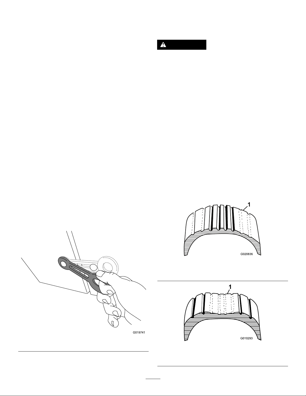
4.Closethecowlandsecurethecowllatches
(Figure13).
g019741
Figure13
5.Extendtheaxle;refertoExtendingtheAxle
(page17).
CheckingtheTiresandWheels
ServiceInterval:Beforeeachuseordaily—Inspect
thetiresandwheels.
WARNING
Failuretomaintaincorrecttirepressure
mayresultintirefailureandlossofcontrol,
resultinginpropertydamageandserious
injuryordeath.
•Checkthetirepressurefrequentlyto
ensureproperination.Ifthetiresarenot
inatedtothecorrectpressure,theywill
wearprematurely.
•Inspectthetireconditionbeforetowing
andafteranyoperatingaccident.
TheDOTtireinformationislocatedonthesideof
eachtire.Thisinformationgivesloadandspeed
ratings.Replacementtiresshouldhavethesame
orbetterratings.Formoreinformationgoto
http://www.nhtsa.gov/Vehicle+Safety/Tires.
Note:Thevariousmachinesinthismanualhave
differentweights;refertoSpecications(page12)to
ensurethatthetiresonyourmachinemeetorexceed
theweightrequirementsofyourmachine.
1.Visuallyinspectthetiresfordamageandwear
(Figure14andFigure15).
g020836
Figure14
1.Exampleoftirewearcausedbyunderination
g010293
Figure15
1.Exampleoftirewearcausedbyoverination
14
2.Ensurethatthetiresareinatedtothecorrect
airpressure.ThefollowingTireAirPressure
tableshowstheappropriateairpressureforthe
tiresasinstalledatthefactory.
Important:Alwayschecktheinformationon
theactualtiresforthecorrectairpressure
requirement.
Important:Themostcommoncauseoftire
troubleisunder-ination.Maintainfullair
pressure.
TireAirPressure
ModelTirepressure
68012Max414kPa(60psi)
68018,68019Max241kPa(35psi)
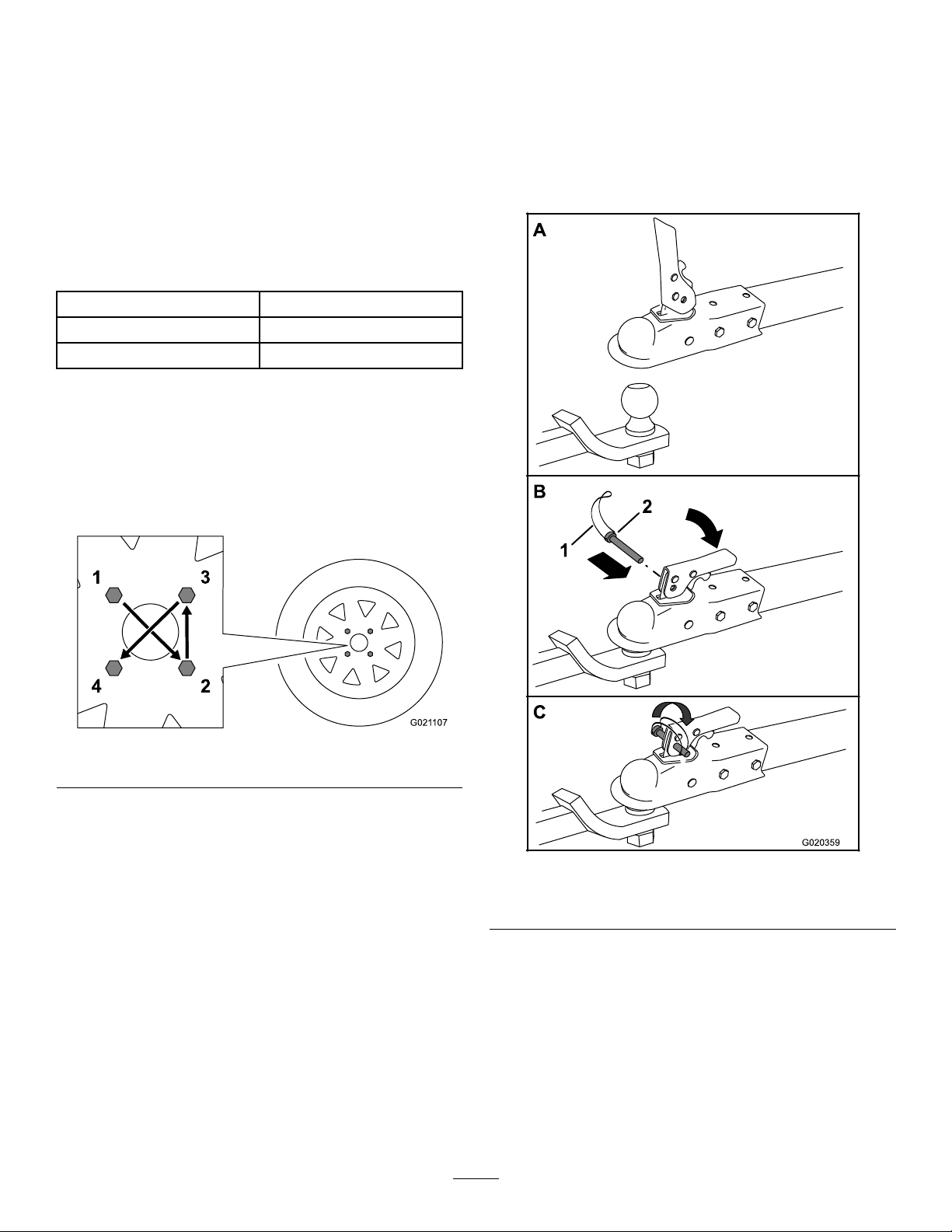
3.Ensurethatthewheellugnutsaretorquedto
108to122N-m(80to90ft-lb).
Note:Checkthetorqueofthewheellugnuts
initiallyandaftertowing.
Note:T orquethelugnutsinthesequence
showninFigure16.
g021107
Figure16
HitchingaMachinewithaStamped
BallCoupler
1.Applychassisgreasetothesocketofthe
couplerandtheareaoftheclampthatcontacts
theball.Oilthepivotpointsandslidingsurfaces
ofthecouplerwithSAE30motoroil.
2.Openthecouplerlatch(Figure17).
g020359
Figure17
1.Bail2.Safetypin
3.Positionthecouplerontopofthehitchball
(Figure17).
4.Closethecouplerlatch(Figure17).
5.Openthebailonthesafetypinandinsertthepin
throughtheholeinthelatch(Figure17).
6.Rotatethefreeendofthebailovertheendof
thesafetypinthatisprotrudingthroughthelatch
(Figure17).
15
7.Ifthemachineisequippedwithatrailer-lightkit,
connectthewireplugofthetowvehicletothe
wireplugofthemachine.
HitchingaMachinewithaForged
BallCoupler
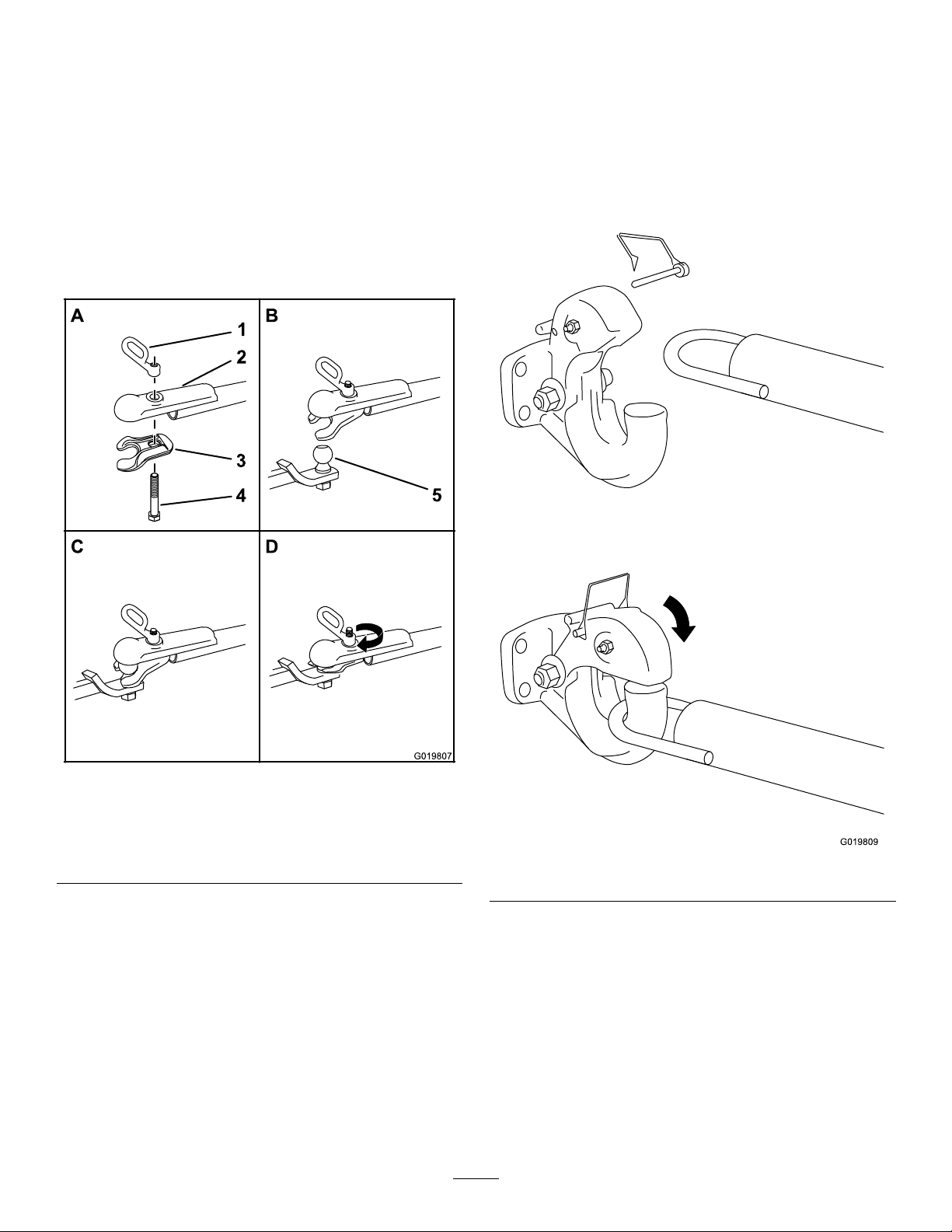
1.Applyremovablethread-lockingcompoundto
thethreadsofthecouplerbolttopreventthe
couplerhandlefromcomingloose(Figure18).
Important:Applythread-lockingcompound
asneededinthefuture.
g019807
Figure18
1.Couplerhandle4.Bolt
2.Coupler5.Hitchball
3.Clamp
2.Applychassisgreasetothesocketofthecoupler
andtheareaoftheclampthatcontactstheball.
3.Pushthecouplerboltupthroughthecoupler
clampandthecouplertop,andconnectthe
couplerhandletothebolt(Figure18).
4.Positionthecouplersothesocketisontopof
thehitchballandtheclampisundertheball.
5.Turnthecouplerhandleclockwisetothreadit
ontotheboltuntilitissecure(Figure18).
Note:Useawrenchtokeeptheboltfrom
spinning.
6.Ifthemachineisequippedwithatrailer-lightkit,
connectthewireplugofthetowvehicletothe
wireplugofthemachine.
HitchingaMachinewithaPintle
HitchTowPole
1.Removethepinfromthepintlehitchandopen
it(Figure19).
g019809
Figure19
2.Positiontheringonthetowpoleontothehook
ofthepintlehitch(Figure19).
3.Closethetopofthepintlehitchandsecureit
withthepin(Figure19).
4.Ifthemachineisequippedwithatrailer-lightkit,
connectthewireplugofthetowvehicletothe
wireplugofthemachine.
16
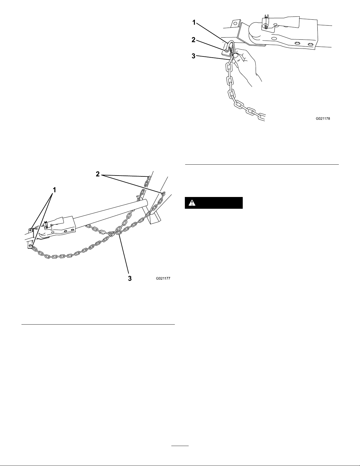
ConnectingtheSafetyChainsto
theTowVehicle
Connectthesafetychaintothemachineandthetow
vehicleasfollows:
1.Pullthesafetychainthroughtheslotsinthe
keyholeslocatedinthefrontpostofthemachine,
sothatthereisjustenoughslackoneachside
forturningaroundcornerswhentowingthe
machine(Figure20).
Note:Stowtheexcesschaininsidethebottom
ofthefrontpostbypushingitintothekeyholes
andlatchingtheappropriatelinksintothe
keyholeslots.
2.Crossbothlengthsofchainunderthetowpole.
Note:Crossingthechainsdecreasesthe
chancesofthefrontofthemachinedropping
tothegroundifthehitchdoesnotholdthe
connection.
g021177
Figure20
1.Connectinglinks3.Chaincrossedundertow
pole
2.Keyholesinfrontpost
3.Connecteachlengthofchaintothesafety
chainmountingpointonthetowvehiclewiththe
connectinglinks(Figure21).
g021178
Figure21
1.Connectinglink3.Chainlink
2.Safetychainmounting
pointontowvehicle
ExtendingtheAxle
WARNING
Themachineisnotstablewhentowingitwith
theaxleinthenarrowposition.
Towthemachinewiththeaxleinthewide
position.
Important:Adjusttheaxletothenarrowposition
onlytomovethemachinethroughanarrow
accesspoint,suchasthegateofafenceorthe
doorwayofabuilding.
PreparingtoChangetheAxle
Width
1.Movethemachinetoaleveljob-sitesurface.
2.Disconnectthemachinefromthetowvehicle.
3.Chockthetires.
4.Ensurethatthedrumisemptyandinthemix
position(upright).
5.Ensurethatthedrumlatchisengagedand
thatthedrumdoesnotrotatetowardthedump
position.
17
AdjustingtheAxleWidth
WARNING
Mechanicalorhydraulicjacksmayfailto
supportthemachineandcauseseriousinjury.
Usejackstandswhensupportingthe
machine.
1.Alignajackwithanadequateliftheight
andweightcapacityundertheaxle;referto
Specications(page12).
2.Liftthemachineuntilthetiresareofftheground.
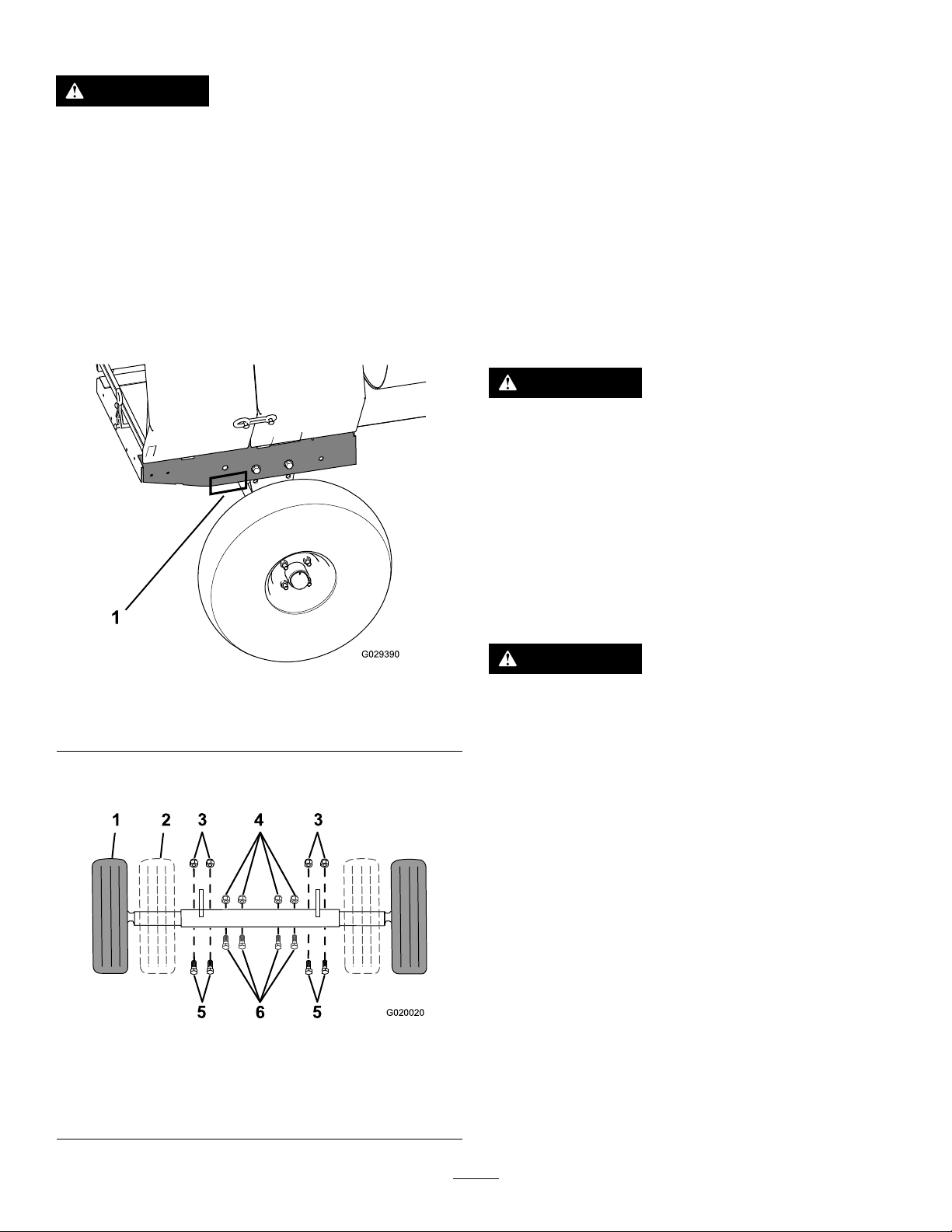
3.Useajackstandateachsupportpointonthe
rearframeextension(Figure22).
g029390
Figure22
1.Supportpoint(2)
4.Removetheboltsandnutsthatsecuretheinner
axletotheouteraxle(Figure23).
g020020
Figure23
1.Wideposition(towing)4.Nut(narrowposition)
2.Narrowposition5.Bolt(wideposition)
3.Nut(wideposition)6.Bolt(narrowposition)
5.Aligntheinneraxletothedesiredpositionas
follows:
•Slideeachsideoftheaxleinwardtothe
narrowposition(Figure23).
•Slideeachsideoftheaxleoutwardtothe
wide(tow)position(Figure23).
6.Aligntheholesoftheinneraxlewiththeholes
oftheouteraxle.
7.Inserttheboltsthroughtheaxleholes(Figure
23).
8.Threadthenutsontothebolts,andtorquethe
nutsto87N-m(64ft-lb).
TowingtheMachine
WARNING
Towingthemachineathighspeedincreases
theriskofahitchmalfunctionandtirefailure.
Higherspeedsalsoincreasethemomentum
ofthemachineandbrakingdistance.Ifthe
machinebecomesdetachedfromthetow
vehicleathighspeed,itcouldcausedamage
toproperty,orinjuryordeathtobystanders.
Donotexceed88km/h(55mph)whentowing
themachine.Forpoorroadconditionsor
inclementweather,reducespeedaccordingly.
WARNING
Towingthemachinewithmaterialinthedrum
increasestheriskofahitchmalfunctionand
tirefailure.Inaddition,materialcouldbounce
outofthedrumandhitothervehiclesand/or
people.Materialinthedrumincreasesthe
weight,whichaffectsmomentumandbraking
distance.
Donottowthemachinewithmaterialinthe
drum.
•ReviewandunderstandSafeOperatingPractices
(page3).
•Testthebrakesofthetowvehiclebeforetowing.
•Avoidsuddenstartsandstopswhiletowingthe
machine.
PreparingtoUsethe
Machine
•Reviewallofthesafetydecalsonthemachine.
•Useahard-hat,hearingprotection,ashirtwith
longsleevesthataretightatthewrists,tight-tting
18

gloveswithoutdrawstringsorloosecuffs,eye
protection,andadustmaskorrespirator.A
meshvisoralonedoesnotprovidesufcienteye
protection;supplementwithprotectiveglasses.
•Ensurethatyouarefamiliarwiththesafety
regulationsandshutdownproceduresdescribedin
theOperator’sManual.
•Ensurethatallguardsareinplaceandingood
condition.
•Ensurethatthepaddlesareinplaceandingood
condition.
•Checkallthegreasettingstoensurethatthe
machineisproperlylubricated.
•Whenpreparingtomixmaterial:
1.Movethemachinetoaleveljob-sitesurface.
2.Removethemachinefromthetowvehicle.
3.Chockthefrontandbackofthetiresto
preventthemachinefrommoving.
4.Ensurethatthedrumisinthemixposition
(upright).
5.Ensurethatthedrumlatchisengagedand
thatthedrumdoesnotrotatetowardthe
dumpposition.
OpeningandClosingthe
Cowl
OpeningtheCowl
1.Atthesideofthemachinewherethefrontcowl
andrearcowlmeet,graspthelatchandpullitoff
fromthelatchanchorontherearcowl(Figure
24).
g020906
Figure24
1.Latch3.Receiver
2.Latchanchor4.V-tting
2.Repeatstep1ontheoppositesideofthe
machine.
3.Atthebackofthemachinewheretherearcowl
meetstheframeofthemachine,graspthelatch
andpullitofffromthelatchanchoronthecowl
(Figure24).
4.Rotatetherearcowlupandforwarduntilitis
fullypositionedontopofthefrontcowl(Figure
24).
ClosingtheCowl
1.Rotatetherearcowlrearwardanddownuntil
thereceiveratthebottomcenterofthecowlis
alignedwiththeV-ttingandushontheframe
ofthemachine(Figure24).
19
2.Atthebackofthemachine,graspthelatchand
pullitontothelatchanchorontherearcowl.
3.Atthesideofthemachine,graspthelatchand
pullitontothelatchanchorontherearcowl.
4.Repeatstep3attheoppositesideofthe
machine(Figure24).
PoweringtheMachine
SettingtheOperatingVoltage
Themachinecanoperatewitha115Vor230Vsupply
voltage.Thevoltageblockdeterminestheoperating
voltageofthemachine(Figure10).Usethefollowing
stepstochangetheoperatingvoltage:
1.Parkthemachineonlevelground.
2.Stopthemotorandunplugthemachine.
3.Removethe2screwssecuringthevoltageblock
tothemotor.
4.Removethevoltageblockfromthemotor,rotate
thevoltageblock180degreesandplugitback
intothemotor.
5.Securethevoltageplugtothemotorwiththe2
screwsthatyoupreviouslyremoved.
Note:Usetheinstructionsonthevoltageblockto
determinethevoltageblocksetting.
ConnectingtoaPowerSource
DANGER
Contactwithwaterwhileoperatingthe
productcouldcauseelectricshock,causing
injuryordeath.
•Donothandletheplugorthemachinewith
wethandsorwhilestandinginwater.
•Useonlyanextensioncordrecommended
foroutdoorcold-weatheruse.
Important:Checktheextensioncordfrequently
duringuseforholesorcracksintheinsulation.
Donotuseadamagedcord.Donotrunthecord
throughstandingwaterorwetgrass.
Important:Useonlyextensioncordswith
terminalsandsocketsforthelive,neutral,and
groundwires.
Important:Connectthemachinetoonly
areceptaclewithlive,neutral,andground
connections.
Important:Theconnectingwiresorextension
cordshouldbeasshortaspossibleandin1piece.
Toreducetheriskofelectricshock,thismachine
hasapolarizedplug(uniquebladeshapesand
widths).Useonlyapolarizedplugandsocketthatis
compliantwithNEMAspecicationsandanextension
cordthatisUL-listed(CSAcertiedinCanada)and
recommendedforoutdooruse.Apolarizedplugwillt
inapolarizedcordonly1way.Iftheplugdoesnott
fullyintothecord,turnthecord.Ifitstilldoesnott,
purchaseanappropriateextensioncord.Ifyouhavea
polarizedextensioncordandtheextensioncordplug
doesnottfullyintothewallreceptacle,turntheplug.
Ifitstilldoesnott,contactaqualiedelectricianto
installtheproperoutlet.Donotchangethemachine
plugorextension-cordpluginanyway.
Note:Themachineusesatwist-lockingplug.
ExtensionCords
LengthWireGauge
15.2m(50ft)10AWG
22.8m(75ft)10AWG
30.4m(100ft)8AWG
Note:Donotuseanextensioncordover30.4m
(100ft)long.
20
Other manuals for MMX-650E-S
2
This manual suits for next models
4
Table of contents
Other Toro Mixer manuals


Popular Mixer manuals by other brands


Ruhle
Ruhle MPR 1500 Original instructions

Breville
Breville STAND BEM800XL Instruction booklet

Ametek
Ametek Chandler Engineering 3260 instruction manual

Altrad
Altrad Lescha Euro-Mix 125 operating instructions

Sunbeam
Sunbeam MX8800 - MIXMASTER PROFESSIONAL Service manual

VOX electronics
VOX electronics MX-1080 operating instructions


