Toro CM-658H-S User manual

FormNo.3378-148RevB
CM-658H-S,CM-958H-S,
CM-958H-SED,CM-958H-PED,
andCM-958H-PConcreteMixers
ModelNo.68004—SerialNo.313000001andUp
ModelNo.68006—SerialNo.313000001andUp
ModelNo.68007—SerialNo.313000001andUp
ModelNo.68008—SerialNo.313000001andUp
ModelNo.68009—SerialNo.313000001andUp
G019544
Registeratwww.Toro.com.
OriginalInstructions(EN)*3378-148*B

WARNING
CALIFORNIA
Proposition65Warning
Thisproductcontainsachemicalorchemicals
knowntotheStateofCaliforniatocausecancer,
birthdefects,orreproductiveharm.
Theengineexhaustfromthisproduct
containschemicalsknowntotheStateof
Californiatocausecancer,birthdefects,
orotherreproductiveharm.
Useofthisproductmaycauseexposureto
chemicalsknowntotheStateofCalifornia
tocausecancer,birthdefects,orother
reproductiveharm.
ThissparkignitionsystemcomplieswithCanadianICES-002.
Becauseinsomeareastherearelocal,state,orfederal
regulationsrequiringthatasparkarresterbeusedonthe
engineofthismachine,asparkarresterisavailableas
anoption.Ifyourequireasparkarrester,contactyour
AuthorizedToroServiceDealer.
GenuineTorosparkarrestersareapprovedbytheUSDA
ForestryService.
Important:ItisaviolationofCaliforniaPublic
ResourceCodeSection4442touseoroperatetheengine
onanyforest-covered,brush-covered,orgrass-covered
landwithoutasparkarrestermufermaintainedin
workingorder,ortheengineconstricted,equipped,and
maintainedforthepreventionofre.Otherstatesor
federalareasmayhavesimilarlaws.
Theenclosed
Engine Owner's Man ual
issuppliedfor
informationregardingtheUSEnvironmentalProtection
Agency(EPA)andtheCaliforniaEmissionControl
Regulationofemissionsystems,maintenance,and
warranty.Replacementsmaybeorderedthroughthe
enginemanufacturer.
Introduction
Thismachineisdesignedtomixconcrete,plaster,reproong
material,grout,andothersmall-grainedconcreteproducts.
Themachinecanbetowedbehindavehicleequippedwith
ahitchappropriateforthetypeoftowpoleyourmachine
has(ball,pintle,orpinhitch).
Readthisinformationcarefullytolearnhowtooperateand
maintainyourproductproperlyandtoavoidinjuryand
productdamage.Youareresponsibleforoperatingthe
productproperlyandsafely.
YoumaycontactTorodirectlyatwww .Toro.comforproduct
andaccessoryinformation,helpndingadealer,ortoregister
yourproduct.
Wheneveryouneedservice,genuineToroparts,oradditional
information,contactanAuthorizedServiceDealerorToro
CustomerServiceandhavethemodelandserialnumbersof
yourproductready.Writethenumbersinthespaceprovided.
1G019545
Figure1
Models68004,68006,and68009
1.Modelandserialnumberlocation
G019913
1
Figure2
Models68007and68008
1.Modelandserialnumberlocation
ModelNo.
SerialNo.
Thismanualidentiespotentialhazardsandhassafety
messagesidentiedbythesafetyalertsymbol(Figure3),
whichsignalsahazardthatmaycauseseriousinjuryordeath
ifyoudonotfollowtherecommendedprecautions.
©2013—TheToro®Company
8111LyndaleAvenueSouth
Bloomington,MN554202
Contactusatwww.Toro.com.
PrintedintheUSA
AllRightsReserved

Figure3
1.Safetyalertsymbol
Thismanualuses2wordstohighlightinformation.
Importantcallsattentiontospecialmechanicalinformation
andNoteemphasizesgeneralinformationworthyofspecial
attention.
TireInformation
TheDOTtireinformationislocatedontheside
ofeachtire.Thisinformationgivesloadandspeed
ratings.Replacementtiresshouldhavethesame
orbetterratings.Formoreinformationgoto
http://www.nhtsa.gov/Vehicle+Safety/Tires.
Note:Thevariousmachinesinthismanualhavedifferent
weights;refertoSpecications(page14)toensurethatthe
tiresonyourmachinemeetorexceedtheweightrequirements
ofyourmachine.
Contents
Introduction..................................................................2
Safety...........................................................................4
SafeOperatingPractices...........................................4
SafetyandInstructionalDecals.................................7
Setup............................................................................9
1InstallingtheTowPole—Models68004,68006,
and68009...........................................................9
2InstallingtheTongue—Models68007and
68008.................................................................9
3InstallingtheSafetyChain.....................................10
ProductOverview.........................................................12
Controls...............................................................13
Specications........................................................14
Operation....................................................................14
PreparingtoTowtheMachine..................................14
TowingtheMachine...............................................19
PreparingtoUsetheMachine...................................20
LoweringtheStabilizerLegs....................................20
OpeningandClosingtheCowl.................................21
AddingFuel...........................................................21
CheckingtheEngineOilLevel.................................23
StartingandStoppingtheEngine..............................24
UsingtheMachine..................................................25
MixingtheMaterial.................................................25
UsingtheDrum.....................................................25
Maintenance.................................................................27
RecommendedMaintenanceSchedule(s)......................27
PremaintenanceProcedures........................................27
PreparingtheMachineforMaintenance.....................27
DisconnectingtheSpark-plugWire...........................27
RemovingandInstallingtheDividerPlate..................28
Lubrication...............................................................29
LubricatingtheMachine..........................................29
EngineMaintenance..................................................29
ServicingtheAirCleaner.........................................29
ChangingtheEngineOil.........................................30
ServicingtheSparkPlug..........................................31
ServicingtheSparkArrester.....................................33
FuelSystemMaintenance...........................................34
ServicingtheFuelSystem........................................34
BeltMaintenance......................................................35
ServicingtheDriveBelts.........................................35
CheckingtheDrive-beltTension..............................35
AdjustingtheDrive-beltTension..............................35
ReplacingtheDriveBelts.........................................36
Cleaning...................................................................36
CleaningtheMachine..............................................36
Storage........................................................................37
StoringtheMachine................................................37
Troubleshooting...........................................................38
3

Safety
Improperlyusingormaintainingthemachinecanresult
ininjury.Toreducethepotentialforinjury,complywith
thesesafetyinstructionsandalwayspayattentiontothe
safetyalertsymbol,whichmeans:
Caution
,
W ar ning
,
or
Danger
—personalsafetyinstruction.Failureto
complywiththeinstructionmayresultinpersonalinjury
ordeath.
SafeOperatingPractices
Thisproductiscapableofamputatinghands.Alwaysfollow
allsafetyinstructionstoavoidseriousinjuryordeath.
WARNING
Machiningorhandlingstone,masonry,concrete,
metal,andothermaterialscangeneratedust,mists,
andfumescontainingchemicals,suchassilica,
knowntocauseseriousorfatalinjuryorillness,
suchasrespiratorydisease,silicosis,cancer,birth
defects,orotherreproductiveharm.
•Controldust,mist,andfumesatthesource
wherepossible.Watershouldbeusedfordust
suppressionwhenfeasible.
•Usegoodworkpracticesandfollowthe
recommendationsofthemanufactureror
suppliers,OSHA,andotheroccupationaland
tradeassociations.
•Alwaysfollowrespiratoryprecautions.
•Whenthehazardsfrominhalationcannotbe
eliminated,theoperatorandanybystanders
shouldweararespiratorapprovedbyOSHAfor
thematerialbeinghandled.
WARNING
Engineexhaustcontainscarbonmonoxide,an
odorless,deadlypoisonthatcankillyou.
Donotruntheengineindoorsorinanenclosed
area.
Training
•ReadtheOperator'sManualandothertrainingmaterial.If
theoperator(s)ormechanic(s)cannotreadorunderstand
theinformation,itistheowner'sresponsibilitytoexplain
thismaterialtothem.
•Becomefamiliarwiththesafeoperationoftheequipment,
operatorcontrols,andsafetysigns.
•Alloperatorsandmechanicsshouldbetrained.The
ownerisresponsiblefortrainingtheusers.
•Neverletchildrenoruntrainedpeopleoperateorservice
theequipment.Localregulationsmayrestricttheageof
theoperator.
•Theowner/usercanpreventandisresponsiblefor
accidentsorinjuriestopeopleordamagetoproperty.
Towing
Checkwithyourlocalcountyorstatetowingsafetyregulations
beforetowingthemachine.
•Inordertoreducethepossibilityofanaccidentwhile
transportingthemachineonpublicroads,makesurethat
thetowingvehicleismechanicallysoundandingood
operatingcondition.
•Shutdowntheenginebeforetransportingthemachine.
•Whentowingwithaballhitch,ensurethattheballhitch
youareusingisthepropersizeforthehitchcoupleron
themachine.
•Whentowingwithapintlehitch,ensurethattheeyeof
thetowpoleisthecorrectdimensionforthepintlehook.
•Inspectthehitchandcouplingforwear.Nevertowthe
machinewithdamagedordefectivehitches,couplings,
chains,orothercomponents.
•Checkthetireairpressureonthetowingvehicleandthe
machine.
•Checkthetiretreadandsidewallfordamageandwear.
•Properlyattachthesafetychainstothetowingvehicle.
•Ensurethatthedirectionalandbrakelightsareworking
properly(ifthemachineisequippedwiththelightkit).
•Ensurethatthedirectional,backup,andbrakelightsof
thetowvehicleareworkingproperly(ifthemachineis
equippedwiththelightkit).
•Beforetowing,checktomakecertainyourmachineis
correctlyandsecurelyattachedtothetowingvehicle.
•Ensurethatthesafetychainsareproperlysecuredtothe
vehicle,andleaveenoughslackforturning.
•Donotcarryanymaterialinthemachinewhentowing.
•Avoidsuddenstopsandstarts.Thiscancauseskidding,
orjackkning.Smooth,gradualstartsandstopswill
improvetowing.
•Avoidsharpturnstopreventrolling.Towonlywitha
vehiclethathasahitchdesignedfortowing.Donot
attachtowedequipmentexceptatthehitchpoint.
•Donottowthemachinefasterthan88km/h(55mph).
•Usecautionwhenbackingup;useaspotteroutsidethe
vehicletoguideyou.
•Donotallowanyonetositorrideonthemachine.
•Disconnectthemachinefromthetowvehiclebefore
usingit.
•Placechockblocksunderneaththetirestopreventthem
fromrollingwhilethemachineisparked.
4

Preparation
Becomefamiliarwiththesafeoperationoftheequipment,
operatorcontrols,andsafetysigns.
•Useonlyaccessoriesandattachmentsapprovedbythe
manufacturer.
•Wearpersonalprotectiveequipmentandappropriate
clothing,includingthefollowing:
–Hardhat
–Respiratorordustmask
–Faceshield
–Safetyglasses
–Hearingprotection
–Safetyshoes
–Longpants
–Shirtwithlongsleevesthataretightatthewrists
–Tight-ttinggloveswithoutdrawstringsorloosecuffs
•Securelonghair,looseclothing,orjewelrythatmayget
tangledinmovingparts.
•Operatingtheequipmentsafelyrequiresthefullattention
oftheoperator.Donotwearradioormusicheadphones
whileoperatingthemachine.
•Useextracarewhenhandlingfuels.Theyareammable
andthevaporsareexplosive.Usethefollowingpractices
whenhandlingfuel:
–Useonlyanapprovedfuelcontainer.
–Neverremovethefuelcaporaddfuelwiththeengine
running.
–Allowtheenginetocoolbeforerefueling.
–Donotsmoke.
–Neverrefuelordrainthemachineindoors.
–Replacethefuelcapandtightenitsecurely.
–Keepthecontainernozzleincontactwiththetank
duringlling.
–Neverllacontainerwhileitisinsideavehicle,trunk,
pick-upbed,oranysurfaceotherthantheground.
–Neverstorethemachineorfuelcontainerinside
wherethereisanopename,suchasnearawater
heaterorfurnace.
–Iffuelisspilled,wipeitofftheengineandequipment.
•Ensurethatthemachineisonalevelsurfacebefore
operatingthemachine.
•Chockthetiresofthemachinetopreventunintended
movement.
•Beforeeveryuse,dothefollowing:
–Inspectthecoupler,ball,andhitch.
–Ensurethatalllightsarefunctioningproperly(ifthe
machineisequippedwithalightkit).
–Ensurethatthetiresareproperlyinatedas
recommended.
–Ensurethatthelugnutsaretightandtorqued
properly.
–Ensurethatthemachineisproperlysecured.
Operation
•Neverrunanengineinanenclosedorpoorlyventilated
area.
•Onlyoperatethemachineingoodlightingconditions.
•Beforestartingthemachine,makesurethatthereareno
personsorobstaclesnearorunderthemachine.
•Shutofftheenginebeforeleavingthemachineforany
reason.
Neverleavearunningmachineunattended.Alwaysstop
theengineandverifythatallmovingpartshavestopped.
•Chockthetiresofthemachineorkeepitattachedtothe
towingvehiclewhenitisnotinuse,topreventitfrom
rolling.
•Avoidprolongedbreathingofexhaustfumes.Engine
exhaustfumescancausesicknessordeath.
•Keephandsawayfromanymovingparts.Keepfeetaway
fromthetiresandthefrontpost.
•Donotoperatethemachineundertheinuenceof
alcoholordrugs.
•Ensurethattheareaisclearofotherpeopleorpetsbefore
operatingthemachine.Stopthemachineifanyoneenters
thearea.
•Neverplaceyourhandsoranysolidobjectintothedrum
whenthemachineisinoperation.
•Donottouchpartswhichmaybehotfromoperation.
Allowthemtocoolbeforeattemptingtomaintain,adjust,
orservicethemachine.
•Nevermovethemachinewhiletheengineisrunning.
•Keepthecowlclosedandlatchedduringoperation.
•Ensurethatalltheguardsandshieldsaresecurelyinplace
beforeoperatingthemachine.
•Ifthemixingpaddlesstrikeaforeignobjectorifthe
machineshouldstartmakinganunusualnoiseor
vibration,stoptheengineandemptythedrum.Waitfor
allmovingpartstocometoacompletestopandcool.
Vibrationisgenerallyawarningoftrouble.Inspectfor
cloggingordamage.Cleanandrepairand/orreplace
damagedparts.
•Donotchangetheenginegovernorsettingoroverspeed
theengine.
•Lightningcancausesevereinjuryordeath.Ifyousee
lightningorhearthunderinthearea,donotoperatethe
machine;seekshelter.
5

MaintenanceandStorage
•Beforeperformingmaintenance,dothefollowing:
–Parkthemachineonlevelground.
–Stoptheengine.Waitforallmovementtostopbefore
adjusting,cleaning,orrepairing.
–Lettheenginecoolbeforeperformingmaintenance
orstoring.
–Disengageallpowerandoperationcontrols.
•Neverlubricate,service,repair,oradjustthemachine
whileitisrunning.
•Keepequipmentmaterialsclearfromthemuferand
enginetohelppreventres.Cleanupanyoilorfuel
spillage.
•Neverallowuntrainedpersonneltoservicethemachine.
•Keephands,feet,andclothingawayfrommovingparts.
Ifpossible,donotmakeadjustmentswiththeengine
running.
•Keepallpartsingoodworkingconditionandallhardware
tightened.Replaceallwornordamageddecals.
•Removeanybuildupofgrease,oil,ordebrisfromthe
machine.
•Stopandinspectthemachineifaforeignobjectentersthe
drumorcausesanotherobstruction.Makeanynecessary
repairsbeforestartingthemachine.
•Donottamperwithsafetydevices.
•Chockthetireswhenstoringthemachine.
•Keepallnuts,bolts,screws,andhoseclampssecurely
tightened.Keepequipmentingoodcondition.
•UseonlygenuineTororeplacementpartstoensurethat
theoriginalstandardsaremaintained.
6
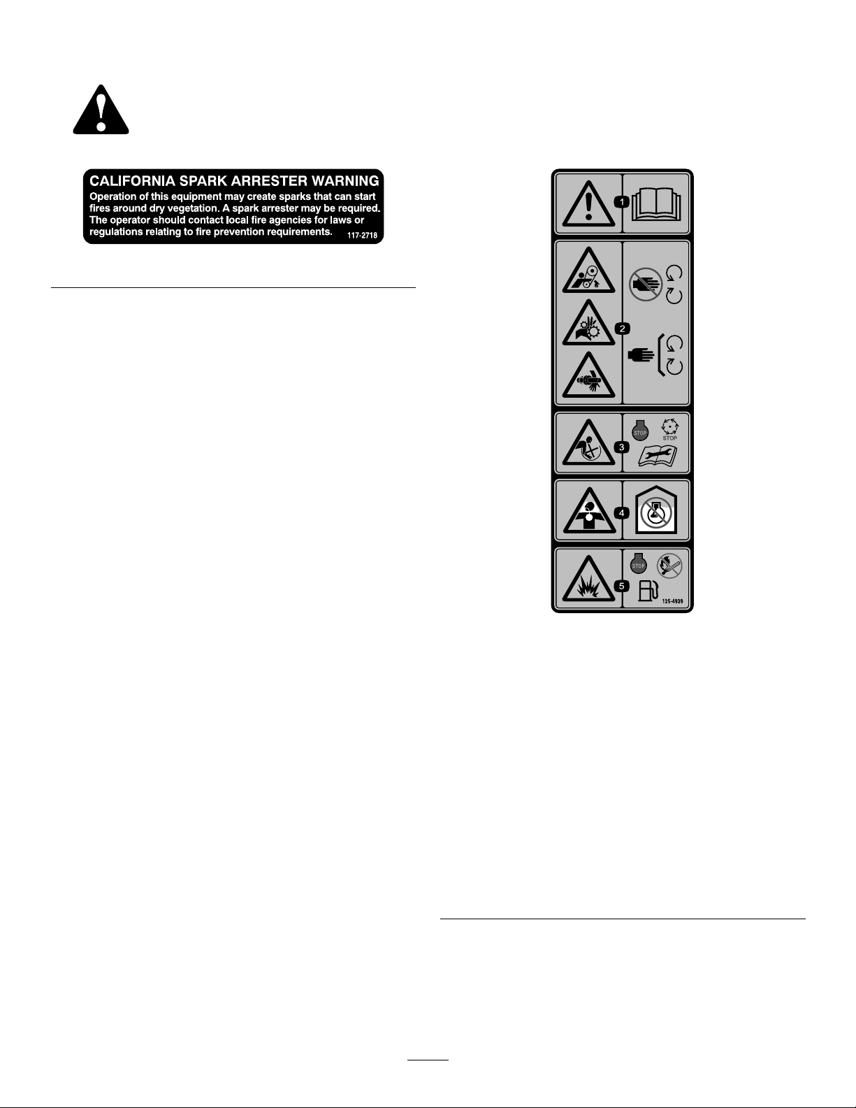
SafetyandInstructionalDecals
Safetydecalsandinstructionsareeasilyvisibletotheoperatorandarelocatednearanyareaofpotential
danger.Replaceanydecalthatisdamagedorlost.
117–2718
125–4939
1.Warning—readthe
Operator’sManual.
4.Toxicgasinhalation
hazard—Don’trunthe
engineinanenclosed
space.
2.Handandarm
entanglementatthe
beltdrive;crushinghazard
ofhand;entanglement
hazardofhandatthe
shaft—keephandsaway
frommovingparts;keep
allguardsandshieldsin
place.
5.Explosionhazard—stop
theengineandkeep
awayfromameswhen
refueling.
3.Entanglementhazardat
paddles—stoptheengine
andwaitforallmoving
partstostopbefore
performingmaintenance.
7
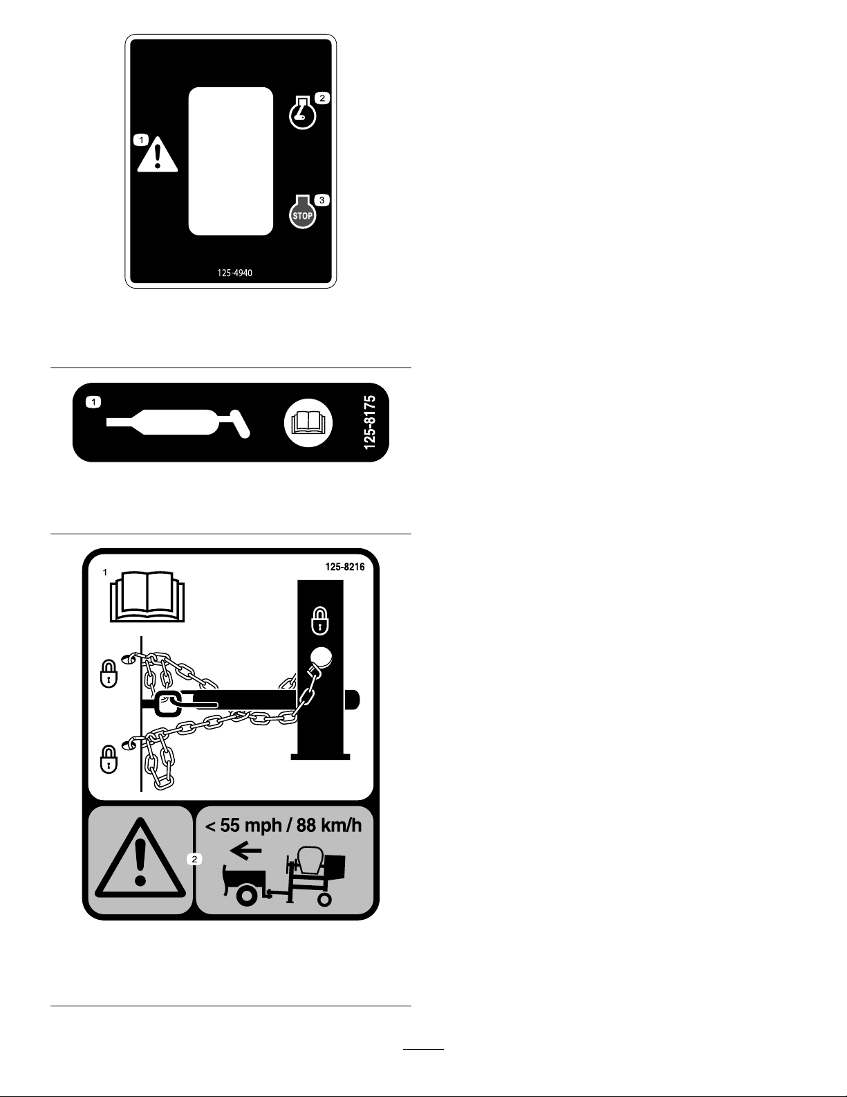
125–4940
1.Warning3.Engine—stop
2.Engine—run
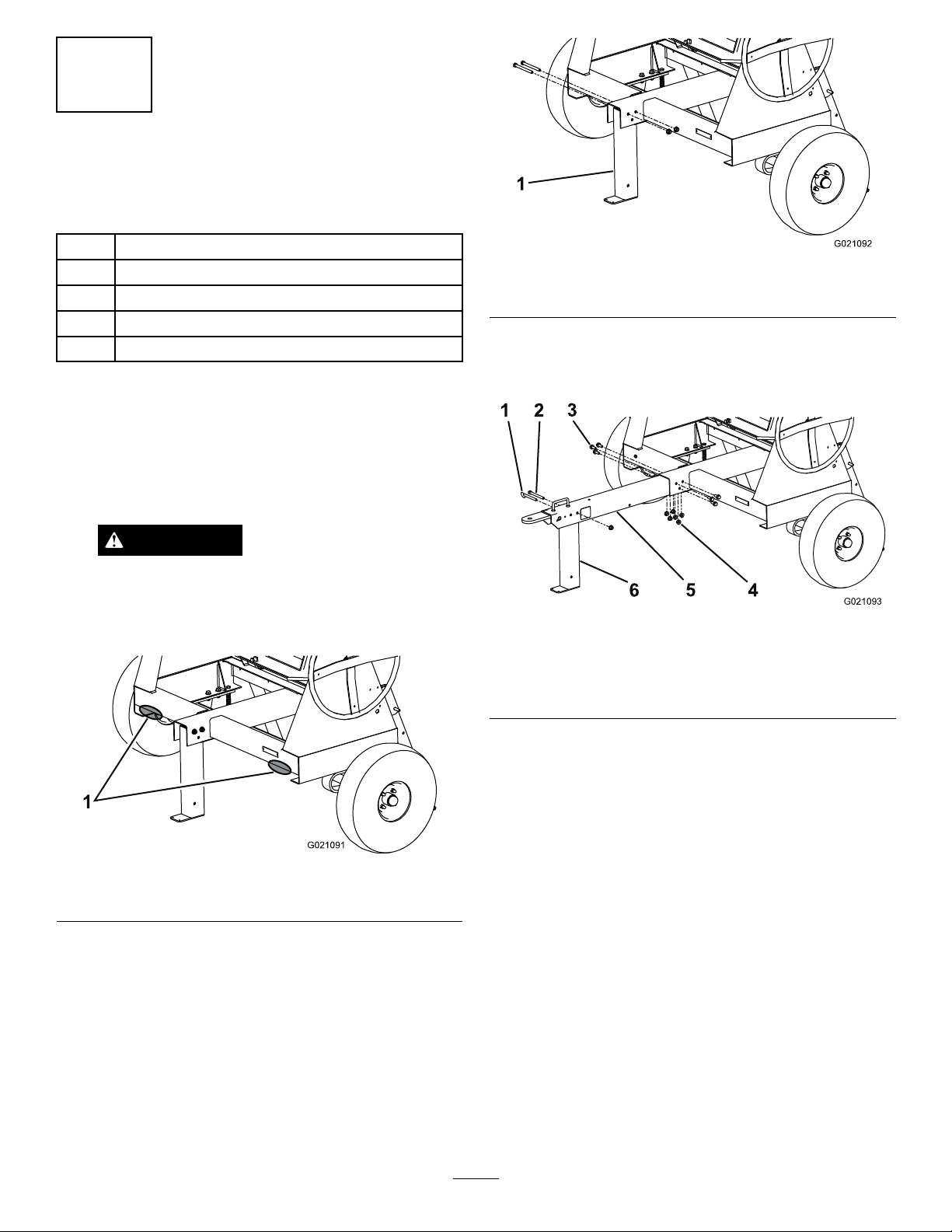
125–8175
1.ReadtheOperator’sManualforinformationongreasing
themachine.
125–8216
1.ReadtheOperator’s
Manualforinformationon
howtotowthemachine.
2.Warning—limittowing
speedtolessthan55mph
/88km/h.
8

Setup
LooseParts
Usethechartbelowtoverifythatallpartshavebeenshipped.
ProcedureDescriptionQty.Use
1Towpolekit(soldseparately)1Installthetowpole.
Tongue1
Frontstabilizerleg1
Shortbolt6
Longbolt1
2
Nut7
Installthetongue.
Safetychain1
3Connectinglink2Installthesafetychain.
1
InstallingtheTow
Pole—Models68004,68006,
and68009
Partsneededforthisprocedure:
1Towpolekit(soldseparately)
InstallingtheTowPoletotheMachine
Note:Thetowpoleispurchasedseparatelyandincludesthe
nutandboltneededforinstallation.
Themachinehasthefollowingtowpoleoptions:
HitchTypeLength
50mm(2inch)ball—stamped78.7cm(31inches)or127cm
(50inches)
50mm(2inch)ball—forged78.7cm(31inches)or127cm
(50inches)
Pintle78.7cm(31inches)or127cm
(50inches)
1.Removetheboltandnutfromthetowpole(Figure4).
5
12
4
6
3
G019804
Figure4
1.Towpole4.Bolthole
2.Frontpost5.Frametting
3.Bolt6.Nut
2.Slidethetowpoleforwardandaligntheholeinthe
polewiththeholeintheframetting(Figure4).
3.Inserttheboltthroughtheholesinthettingandthe
pole(Figure4).
4.Threadthenutontotheboltandtightenthemuntil
theyaretightagainsttheframetting(Figure4).
Note:Iftheself-lockingnyloninsertinthelocknut
wearswithuse,replacethenutwithanewGrade5or
Grade8locknut.
9
2
InstallingtheTongue—Models
68007and68008
Partsneededforthisprocedure:
1Tongue
1Frontstabilizerleg
6Shortbolt
1Longbolt
7Nut
InstallingtheTonguetotheMachine
1.Lowertherearstabilizerlegs;refertoLoweringthe
StabilizerLegs(page20).
2.Placejackstandsunderthefrontframerailtoprevent
themachinefromtippingforward(Figure5).
WARNING
Mechanicalorhydraulicjacksmayfailto
supportthemachineandcauseseriousinjury.
Usejackstandswhensupportingthemachine.
G021091
1
Figure5
1.Supportpoints
3.Removethe2nutsandboltsthatsecurethefront
stabilizerlegtotheframe(Figure6),andremovethe
frontstabilizerleg.
G021092
1
Figure6
1.Frontstabilizerleg
4.Installthetongueintotheopeningatthefrontofthe
machine,andsecureitwith6nutsandshortbolts
torquedto102N-m(75ft-lb);refertoFigure7.
1 2 3
4
5
6
G021093
Figure7
1.Clevispin4.Nut(7)
2.Longbolt5.Tongue
3.Shortbolt(6)6.Frontstabilizerleg
5.Alignthetoprearholeinthefrontstabilizerlegtothe
holepastthehandleinthefrontofthetongue(Figure
7).
6.Installthelongboltthroughtheholes,andsecureit
withanuttorquedto102N-m(75ft-lb);referto
Figure7.
Note:Thestabilizerlegpivotsrearwardonthebolt.
Ifyouinstalltheboltintothewronghole,thestabilizer
legwillnotworkproperly.
7.Inserttheclevispintolockthefrontstabilizerlegin
position(Figure7).
10
3
InstallingtheSafetyChain
Partsneededforthisprocedure:
1Safetychain
2Connectinglink
Models68004,68006,and68009
(Side-dump)
1.Formahookontheendofabendablepieceofrodor
stiffwire,(notincluded),andinsertitthroughboth
keyholesinthefrontpostofthemachine(Figure8A).
A
B
C
D
g019883
2
3
4
3
1
Figure8
1.Keyhole3.Safetychain
2.Rodorwire(notincluded)4.Connectinglink
2.Attachthesafetychaintothelengthofrodorwire
(Figure8A).
3.Pulltherod,orwire,andthesafetychainthroughboth
keyholes(Figure8B).
Note:Ensurethatapproximatelyequallengthsof
safetychainextendfromeithersideofthefrontpost.
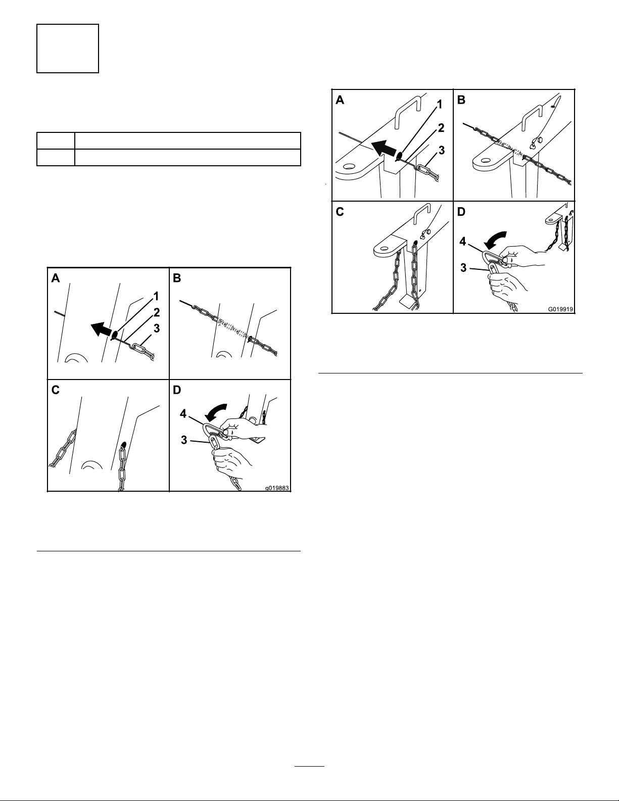
Models68007and68008(End-dump)
1.Formahookontheendofabendablepieceofrod
orstiffwire(notincluded)andinsertitthroughboth
keyholesinthetongueofthemachine(Figure9).
A
B
C
D
G019919
2
3
4
3
1
Figure9
1.Keyhole3.Safetychain
2.Rodorwire(notincluded)4.Connectinglink
2.Attachthesafetychaintothelengthofrodorwire
(Figure9).
3.Pulltherod,orwire,andthesafetychainthroughboth
keyholes(Figure9).
Note:Ensurethatapproximatelyequallengthsof
safetychainextendfromeithersideofthetongue.
InstallingtheConnectingLinks
1.Aligntheconnectinglinktothelastlinkinoneendof
thesafetychain(Figure8DandFigure9D).
2.Inserttheconnectinglinkthroughthechainlinkuntil
theconnectinglinksnapsclosed.
3.Repeatsteps1and2toinstalltheotherconnectinglink
intheotherendofthesafetychain.
11
ProductOverview
G019730
1
2
3
4
5
6
7
8
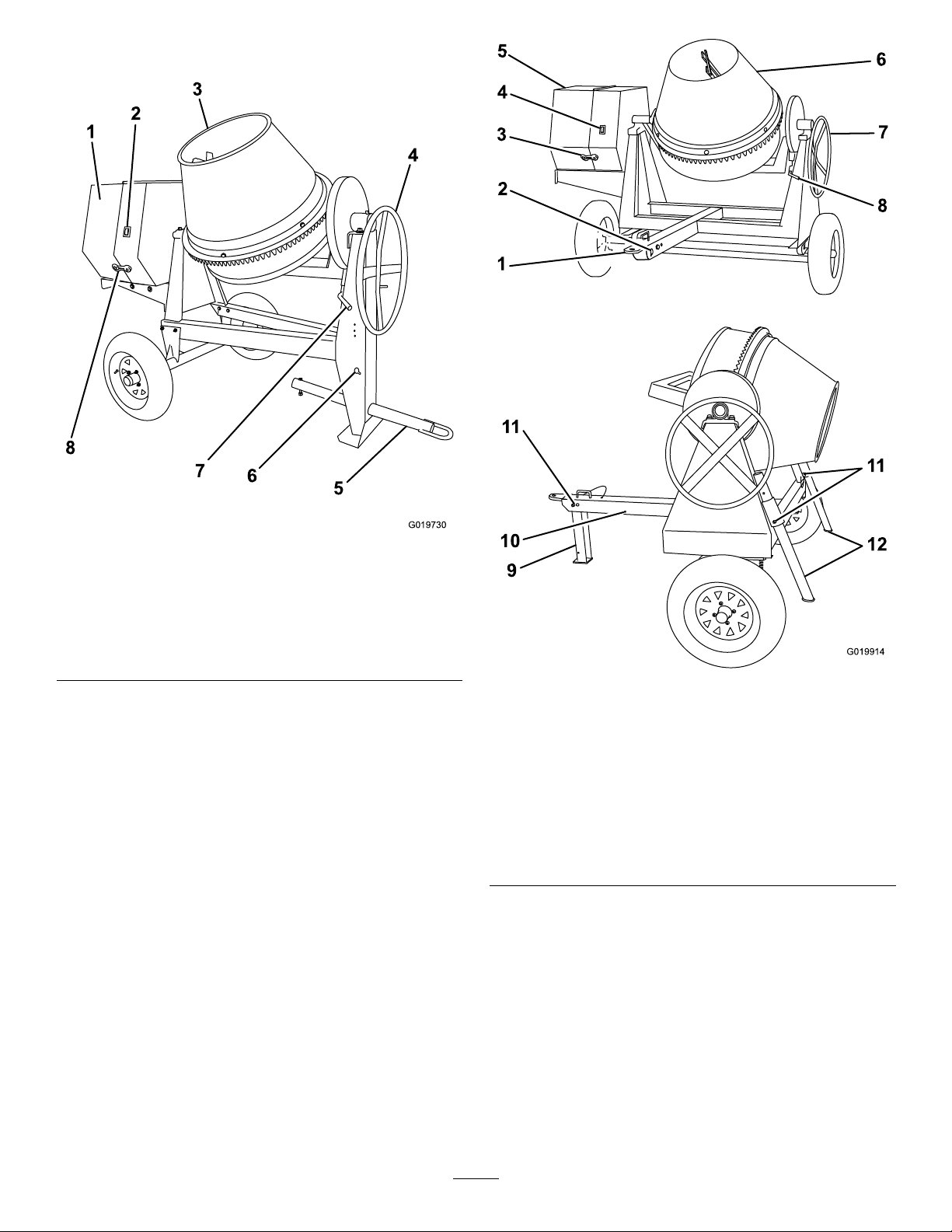
Figure10
Models68004,68006,and68009
1.Enginecowl5.Towpole
2.Engineswitch6.Safety-chainkeyholes
3.Drum7.Drum-tiltbrake
4.Handwheel8.Rubberlatch
5
4
3
2
1
6
7
8
G019914
9
10
11
12
11
Figure11
Models68007and68008
1.Tongue-mountedtow
coupler
7.Handwheel
2.Safety-chainkeyholes8.Drum-tiltbrake
3.Rubberlatch9.Frontstabilizerleg
4.Engineswitch10.Rearwardpinhole
5.Enginecowl11.Clevispin
6.Drum12.Rearstabilizerlegs
12

Controls
Becomefamiliarwithallofthecontrolsbeforeyoustartthe
engineandoperatethemachine.
EngineSwitch
WhentheengineswitchonthecowlisintheRunposition,
itallowstheenginetorun.Movingtheengineswitchtothe
Stoppositionstopstheengine.
Handwheel
Thehandwheelcontrolsthedischargingactionofthedrum.
Drum-tiltBrake
Thedrum-tiltbrakelocksthedrumintoanuprightposition
oradischargingposition.
EngineControls
1
2
3
4
5
6
7
8
G019744
Figure12
1.Recoil-starthandle5.Fuelcap
2.Fuelvalve6.Dipstick
3.Chokelever7.Oil-drainplug
4.Throttlelever8.On/Offswitch
FuelValve
Thefuelvalve(Figure13)islocatedunderneaththechoke
lever.MovetheleverforthefuelvalvetotheOnposition
beforeattemptingtostarttheengine.Whenyouhavenished
mixing,stoptheengineandmovethefuelvalvelevertothe
Offposition.
1
23
G018792
Figure13
1.Fuelvalve3.Throttlelever
2.Chokelever
ChokeLever
Usethechokelever(Figure13)tostartacoldengine.Before
pullingtherecoil-starthandle,movethechokelevertothe
closedposition.Oncetheengineisrunning,movethechoke
levertotheopenposition.Donotusethechokeiftheengine
isalreadywarmeduportheairtemperatureishigh.
ThrottleLever
Thethrottlelever(Figure13)controlsthespeed(rpm)ofthe
engine.Itislocatednexttothechokelever.Itsetstheengine
speedandthereforecanincreaseanddecreasetherotation
speedofthemixingpaddles.Forbestperformance,setthis
controltothefastpositionwhenmixingmaterial.
EngineOn/OffSwitch
TheOn/Offswitch(Figure14)allowstheoperatorofthe
machinetostartandstoptheengine.Thisswitchislocated
onthefrontoftheengine.RotatetheOn/Offswitchtothe
Onpositiontostartandruntheengine.RotatetheOn/Off
switchtotheOffpositiontostoptheengine.
OFF
ON
1
OFF
ON
G021 103
2
Figure14
1.Offposition2.Onposition
13
Recoil-startHandle
Tostarttheengine,pulltherecoil-starthandle(Figure12)
quicklytoturntheengineover.Theenginecontrolsdescribed
abovemustallbesetcorrectlyfortheenginetostart.
Oil-levelSwitch
Theoil-levelswitchislocatedinsidetheengine,anditwill
notallowtheenginetorunintheeventtheoillevelisbelow
thesafeoperatinglimit.
Specications
Note:Specicationsanddesignaresubjecttochangewithoutnotice.
Model6800468006680076800868009
BatchCapacity0.17cubicmeters
(6.0cubicfeet)
0.255cubicmeters
(9.0cubicfeet)
0.255cubicmeters
(9.0cubicfeet)
0.255cubicmeters
(9.0cubicfeet)
0.255cubicmeters
(9.0cubicfeet)
TotalVolume0.255cubicmeters
(9.0cubicfeet)
0.43cubicmeters
(15.1cubicfeet)
0.43cubicmeters
(15.1cubicfeet)
0.43cubicmeters
(15.1cubicfeet)
0.43cubicmeters
(15.1cubicfeet)
DrumMaterialSteelSteelSteelPolyethylenePolyethylene
Length198.1cm
(78inches)
213.4cm
(84inches)
215.9cm
(85inches)
215.9cm
(85inches)
213.4cm
(84inches)
Width116.8cm
(46inches)
142.2cm
(56inches)
215.9cm
(85inches)
215.9cm
(85inches)
142.2cm
(56inches)
Height147.3cm
(58inches)
165.1cm
(65inches)
180.3cm
(71inches)
180.3cm
(71inches)
165.1cm
(65inches)
Weight313kg
(690lb)
362.9kg
(800lb)
396.9kg
(875lb)
396.9kg
(875lb)
380.9kg
(837lb)
Operation
Important:Beforeoperating,checkthefuelandoil
levels,andremovedebrisfromthemachine.Ensurethat
theareaisclearofpeople.
PreparingtoTowtheMachine
Important:Ensurethatyourtowvehiclehastowing
capacityfortheweightofthemachine.
Important:UseaClass2orlargerreceiver.
Note:Ensurethatyourtowvehiclehastheappropriatehitch
totowthemachine;optionsincludea50mm(2inch)ball
hitchorapintlehitch.
Note:Ifthemachineisequippedwithatrailer-lightkit,
ensurethattheelectricalconnectorofthetowvehicleis
compatiblewiththeelectricalconnectorofthemachine.
Ifyourtowvehiclehasadifferenttypeofplug,obtainan
adapterfromanautomotivepartsstore.
1.Ensuretheengineisstopped,thefuelvalveisoff,and
thedrumisempty.
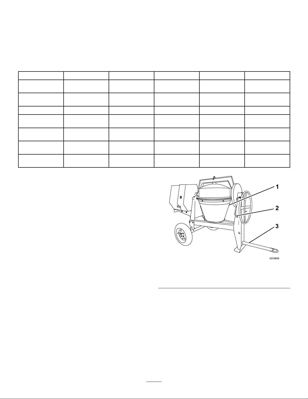
2.Usingthehandwheel,positionthedrumsothatitis
pointingdowntowardtheground(Figure15).
G019806
1
2
3
Figure15
1.Drumpointingdown3.Towpoleboltedinplace
2.Drum-tiltbrakeengaged
3.Lockthedrumintopositionbypushingdownonthe
drum-tiltbrakehandle(Figure16).
14

1
2
G019733
Figure16
Drum-TiltBrake
1.Unlockedposition2.Lockedposition
4.Ensuretheenginecowlisclosedandlatched;referto
ClosingtheCowl(page21).
5.Inspectthetiresandwheels;refertoCheckingthe
TiresandWheels(page15).
CheckingtheTiresandWheels
ServiceInterval:Beforeeachuseordaily—Inspectthetires
andwheels.
WARNING
Failuretomaintaincorrecttirepressuremayresult
intirefailureandlossofcontrol,resultingin
propertydamageandseriousinjuryordeath.
•Checkthetirepressurefrequentlytoensure
properination.Ifthetiresarenotinatedto
thecorrectpressure,theywillwearprematurely.
•Inspectthetireconditionbeforetowingand
afteranyoperatingaccident.
TheDOTtireinformationislocatedontheside
ofeachtire.Thisinformationgivesloadandspeed
ratings.Replacementtiresshouldhavethesame
orbetterratings.Formoreinformationgoto
http://www.nhtsa.gov/Vehicle+Safety/Tires.
Note:Thevariousmachinesinthismanualhavedifferent
weights;refertoSpecications(page14)toensurethatthe
tiresonyourmachinemeetorexceedtheweightrequirements
ofyourmachine.
1.Visuallyinspectthetiresfordamageandwear(Figure
17andFigure18).
G020836
Figure17
1.Exampleoftirewearcausedbyunderination
Figure18
1.Exampleoftirewearcausedbyoverination
2.Ensurethatthetiresareinatedtothecorrectair
pressure.ThefollowingTireAirPressuretableshows
theappropriateairpressureforthetiresasinstalledat
thefactory.
Important:Alwayschecktheinformation
ontheactualtiresforthecorrectairpressure
requirement.
Important:Themostcommoncauseoftire
troubleisunderination.Maintainfullair
pressure.
TireAirPressure
ModelTirepressure
68004CMax414kPa(60psi)
68006C,68007C,68008C,
68009C
Max241kPa(35psi)
3.Ensurethatthewheellugnutsaretorquedto108to
122N-m(80to90ft-lb).
Note:Checkthetorqueofthewheellugnutsinitially
andaftertowing.
Note:Torquethelugnutsinthesequenceshownin
Figure19.
15

1
2
3
4
G021 107
Figure19
RaisingtheStabilizerLegs(Models
68007and68008)
Models68007and68008haveafrontstabilizerlegand2rear
stabilizerlegs.
Raisethestabilizerlegsbeforetowingthemachine.
1.Adjustthemachinesothatthereisnoweightresting
ontherearstabilizerlegs.
2.Pulltheclevispinoutfromoneoftherearstabilizer
legsandthebracket(Figure20).
G019917
Figure20
3.Slidethestabilizerlegupinthebracketandalignthe
pinholeofthebracketwiththelowerholeinthe
stabilizerleg(Figure20).
4.Pushtheclevispinthroughtheholeinthebracketand
thestabilizerleg(Figure20).
5.Repeatsteps1through4fortheotherrearstabilizer
leg.
6.Liftupwardonthetonguesothatthereisnoweight
restingonthefrontstabilizerleg.
7.Pulltheclevispinoutfromthefrontstabilizerlegand
thetongue(Figure21).
G019915
3
2
1
Figure21
1.Removetheclevispin.3.Installtheclevispin.
2.Rotatethestabilizerleg
up.
8.Rotatethefrontstabilizerlegupintothetongue
(Figure21).
9.Pushtheclevispinthroughtherearwardholeinthe
tongueandthefrontstabilizerleg(Figure21).
HitchingaMachinewithaStampedBall
Coupler
1.Applychassisgreasetothesocketofthecouplerand
theareaoftheclampthatcontactstheball.
2.Oilthepivotpointsandslidingsurfacesofthecoupler
withSAE30motoroil.
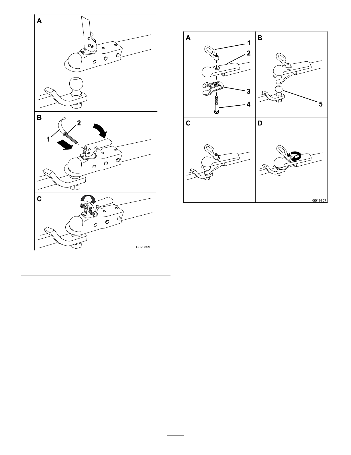
3.Openthecouplerlatch(Figure22).
16
A
B
C
G020359
2
1
Figure22
1.Bail2.Safetypin
4.Positionthecouplerontopofthehitchball(Figure
22A).
5.Closethecouplerlatch(Figure22B).
6.Openthebailonthesafetypin,andinsertthepin
throughtheholeinthelatch(Figure22B).
7.Rotatethefreeendofthebailovertheendofthesafety
pinthatisprotrudingthroughthelatch(Figure22C).
8.Ifthemachineisequippedwithatrailer-lightkit,
connectthewireplugofthetowvehicletothewire
plugofthemachine.
HitchingaMachinewithaForgedBall
Coupler
1.Applyremovablethread-lockingcompoundtothe
threadsofthecouplerbolttopreventthecoupler
handlefromcomingloose(Figure23).
Important:Applythread-lockingcompoundas
neededinthefuture.
A
B
C
D
G019807
5
1
2
3
4
Figure23
1.Couplerhandle4.Bolt
2.Coupler5.Hitchball
3.Clamp
2.Applychassisgreasetothesocketofthecouplerand
theareaoftheclampthatcontactstheball.
3.Pushthecouplerboltupthroughthecouplerclamp
andthecouplertop,andconnectthecouplerhandle
tothebolt(Figure23A).
4.Positionthecouplersothatthesocketisontopofthe
hitchballandtheclampisundertheball(Figure23C).
5.Turnthecouplerhandleclockwisetothreaditontothe
boltuntilitissecure(Figure23D).
Note:Useawrenchtokeeptheboltfromspinning.
6.Ifthemachineisequippedwithatrailer-lightkit,
connectthewireplugofthetowvehicletothewire
plugofthemachine.
17

HitchingaMachinewithaPintleHitch
Coupler
1.Removethepinfromthepintlehitchandopenit
(Figure24).
G019809
Figure24
2.Positiontheringonthetowpoleontothehookofthe
pintlehitch(Figure24).
3.Closethetopofthepintlehitchandsecureitwiththe
pin(Figure24).
4.Ifthemachineisequippedwithatrailer-lightkit,
connectthewireplugofthetowvehicletothewire
plugofthemachine.
HitchingaMachinewithaPinHitch
Coupler
1.Positionthefrontofthepinhitchcouplersothatit
islocatedbetweenthetopandbottomplatesofthe
pin/clevisreceiverhitchofthetowvehicle,andensure
thattheholesarealigned(Figure25B).
A
B
C
D
G020084
1
2
3
4
Figure25
1.Hitchpin3.Pinhitchcoupler
2.Hairpincotter4.Pin/clevisreceiverhitch
2.Inserta19mm(3/4inch)or22mm(7/8inch)hitch
pinthroughtheholesinthecouplerandthereceiver
hitch(Figure25B).
3.Insertahairpincotterthroughtheholeinthebottom
ofthehitchpin(Figure25C).
4.Ifthemachineisequippedwithatrailer-lightkit,
connectthewireplugofthetowvehicletothewire
plugofthemachine.
18
ConnectingtheSafetyChainstothe
TowVehicle
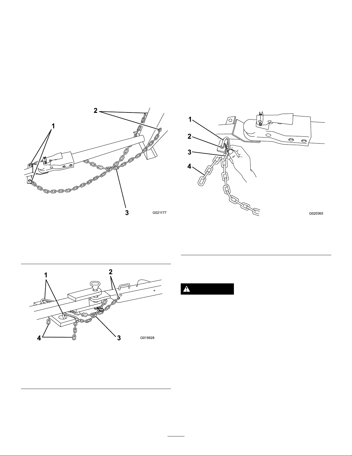
1.Pullthesafetychainthroughtheslotsinthekeyholes,
sothatthelengthsoneachsideareequal.
2.Crossbothlengthsofchainunderthetowpole(under
thetongueforend-dumpmodels68007and68008).
Formodels6800468006,and68009refertoFigure26.
Formodels68007and68008refertoFigure27.
Note:Crossingthechainsdecreasesthechancesof
thefrontofthemachinedroppingtothegroundifthe
hitchdoesnotholdtheconnection.
1
2
3G021 177
Figure26
Models68004,68006,and68009
1.Connectinglinks3.Chaincrossedundertow
pole
2.Keyholesinfrontpost
12
3
4G019928
Figure27
Models68007and68008
1.Connectinglinks3.Chaincrossedunder
tongue
2.Keyholes4.Chain
3.Connecteachlengthofchaintothesafetychain
mountingpointonthetowvehiclewiththeconnecting
links(Figure28).
Important:Ensurethatthechainhasenough
slackforturningaroundcornerswhentowingthe
machine.
Note:Formodels68004,68006,and68009,stow
theexcesschaininsidethebottomofthefrontpost
bypushingitintothekeyholesandlatchingthe
appropriatelinksintothekeyholeslots.
Note:Formodels68007and68008,connectthe
connectinglinkstotheappropriatelinksinthesafety
chain(Figure28).Iftheexcesschainhangstoolowand
touchestheground,connectitagaintotheconnecting
linktoraiseitawayfromtheground.
G020365
1
2
3
4
Figure28
1.Connectinglink3.Chainlink
2.Safetychainmounting
pointontowvehicle
4.Chain
TowingtheMachine
WARNING
Towingthemachineathighspeedincreasesthe
riskofahitchmalfunctionandtirefailure.Higher
speedsalsoincreasethemomentumofthemachine
andbrakingdistance.Ifthemachinebecomes
detachedfromthetowvehicleathighspeed,it
couldcausedamagetoproperty,orinjuryordeath
tobystanders.
Donotexceed88km/h(55mph)whentowingthe
machine.Forpoorroadconditionsorinclement
weather,reducespeedaccordingly.
19
WARNING
Towingthemachinewithmaterialinthedrum
increasestheriskofahitchmalfunctionandtire
failure.Inaddition,materialcouldbounceoutof
thedrumandhitothervehiclesand/orpeople.
Materialinthedrumincreasestheweight,which
affectsmomentumandbrakingdistance.
Donottowthemachinewithmaterialinthedrum.
•ReviewandunderstandSafeOperatingPractices(page4).
•Testthebrakesofthetowvehiclebeforetowing.
•Avoidsuddenstartsandstopswhiletowingthemachine.
PreparingtoUsetheMachine
•Reviewallofthesafetydecalsonthemachine.
•Useahard-hat,hearingprotection,ashirtwithlong
sleevesthataretightatthewrists,tight-ttinggloves
withoutdrawstringsorloosecuffs,eyeprotection,and
adustmaskorrespirator.Ameshvisoralonedoes
notprovidesufcienteyeprotection;supplementwith
protectiveglasses.
•Ensurethatyouarefamiliarwithsafetyregulationsand
shutdownproceduresdescribedinthisOperator’sManual
andtheEngineOwner’sManual.
•Ensurethatallguardsareinplaceandingoodcondition.
•Ensurethatthepaddlesareinplaceandingood
condition.
•Formodels68007and68008,lowerthefrontandrear
stabilizerlegs.
•Checkthefuelandoillevelsoftheengine.
•Whenpreparingtomixmaterial:
1.Movethemachinetoaleveljob-sitesurface.
2.Removethemachinefromthetowvehicle.
3.Chockthefrontandbackofthetirestoprevent
themachinefrommoving.
4.Ensurethatthedrumisinthemixposition
(upright).
5.Ensurethatthedrumlatchisengagedandthatthe
drumdoesnotrotatetowardthedumpposition.
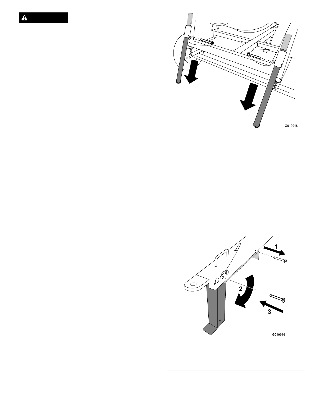
LoweringtheStabilizerLegs
Models68007and68008only
Models68007and68008haveafrontstabilizerlegand2rear
stabilizerlegstokeepthemachinefromtippingforwardor
backwardduringoperation.Movethestabilizerlegsintothe
loweredpositionbeforeoperatingthemachine.
1.Pulltheclevispinoutfromoneoftherearstabilizer
legsandthebracket(Figure29).
G019918
Figure29
2.Slidethestabilizerlegdowninthebracketandalign
thepinholeofthebracketwiththeupperholeinthe
stabilizerleg(Figure29).
3.Pushtheclevispinthroughtheholeinthebracketand
thestabilizerleg(Figure29).
4.Repeatsteps1through3fortheotherrearstabilizer
leg.
5.Liftupwardonthetonguetoprovideclearanceforthe
frontstabilizerleg.
6.Pulltheclevispinoutfromthefrontstabilizerlegand
thetongue(Figure30).
G019916
1
2
3
Figure30
1.Removetheclevispin.3.Installtheclevispin.
2.Rotatethestabilizerleg
down.
7.Rotatethefrontstabilizerlegdowntowardtheground
(Figure30).
20
Other manuals for CM-658H-S
1
This manual suits for next models
14
Table of contents
Other Toro Mixer manuals


