Torq Fusion GT1300PSS User manual
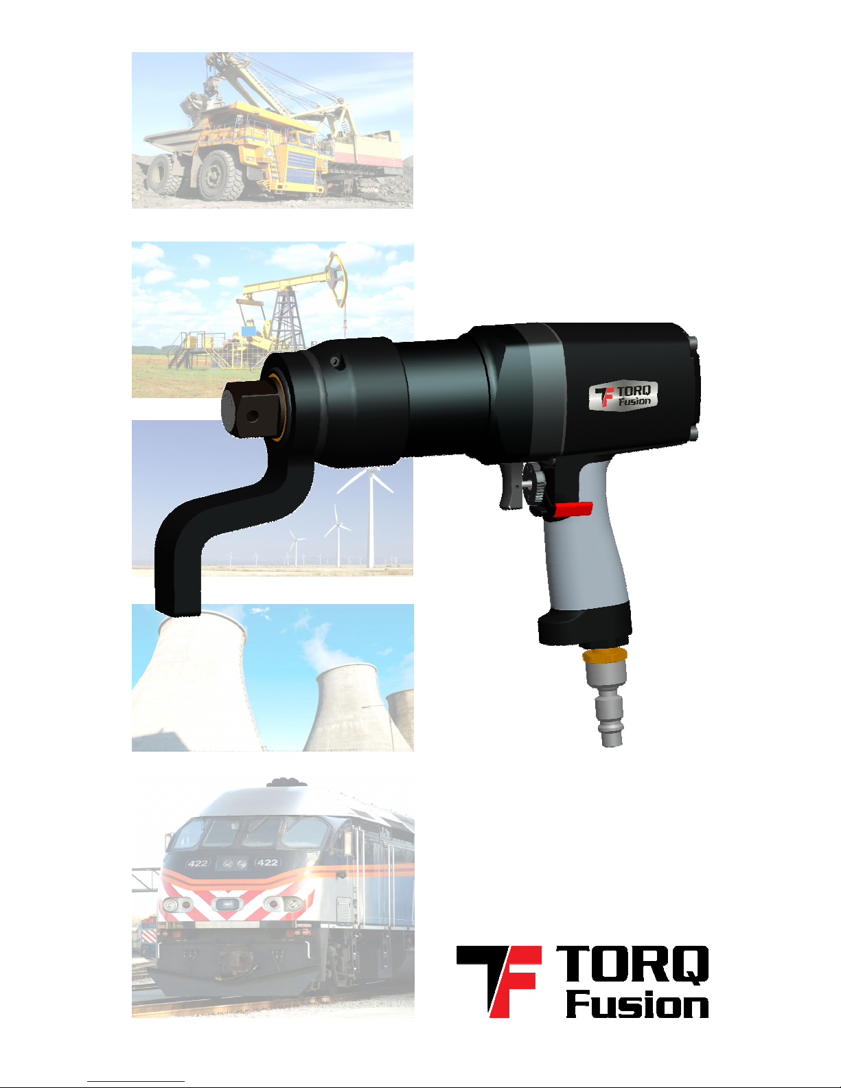
MODEL GT1300PSS
USER MANUAL
®
PNEUMATIC
TORQUE
WRENCH

USER MANUAL: GT1300PSS
©
WWW.TORQFUSION.COM
2 OF 32
REV 1308
®

USER MANUAL: GT1300PSS
©
WWW.TORQFUSION.COM
3 OF 32
REV 1308
®
INTRODUCTION
Than you for choosing TORQ Fusion as your torque tool
manufacturer. We understand that our customers have many
options when selecting their equipment and we truly appreciate
the opportunity to serve your bolting needs.
Our company firmly believes that the development of any product
starts with first understanding the needs of our customers and
apprehending the challenges they encounter with the equipment
they currently use. The TORQ Fusion design team then tac les
these challenges and implements innovative resolutions in the
design it develops. Next we prototype and evaluate our designs
gauging not only performance, but also robustness. Every one of
our designs goes through an exhaustive life test ta ing into
account every possible situation that might occur during normal
operation. As our tools enter the production phase, each unit is
calibrated throughout its operating range and our technical staff
reviews each calibration certificate before signing off and
releasing it.
Please ta e the time to review the rest of this manual, paying
special attention to the safety instructions associated with your
equipment.
If you have additional questions please feel free to contact your
sales representative or the factory by email at
info@torqfusion com
.
Than you again for choosing TORQ Fusion!

USER MANUAL: GT1300PSS
©
WWW.TORQFUSION.COM
4 OF 32
REV 1308
®
TABLE OF CONTENTS
INTRODUCTION .....................................................................................................3
TABLE OF CONTENTS ............................................................................................4
SAFETY.....................................................................................................................5
PPE – (Personal Protective Equipment).......................................................................5
WARRANTY.............................................................................................................6
ABOUT THE TOOL ..................................................................................................7
ABOUT THE FRL.......................................................................................................9
INSTALLATION ......................................................................................................11
OPERATING INSTRUCTIONS................................................................................12
REMOVING AND INSTALLING THE TOOL EXTENSION................................................13
REMOVING AND INSTALLING THE REACTION ARM..................................................13
REMOVING AND INSTALLING THE OUTPUT DRIVE.....................................................15
INSTALLING THE IMPACT SOCKET................................................................................16
DETERMINING THE SET PRESSURE.................................................................................17
LINEAR INTERPOLATION................................................................................................18
ADJUSTING THE SET PRESSURE .....................................................................................19
TIGHTENING ...................................................................................................................20
LOOSENING...................................................................................................................21
BEST PRACTICES ............................................................................................................22
CARE AND MAINTENANCE ...............................................................................22
TORQUE TOOL...............................................................................................................22
FRL - CLEANING THE FILTER ..........................................................................................23
FRL - ADDING TOOL OIL...............................................................................................23
FRL – REPLACING THE BATTERY ...................................................................................24
TOOL CALIBRATION............................................................................................25
TROUBLESHOOTING............................................................................................26
TOOL SPECIFICATION .........................................................................................27
PARTS & ACCESSORIES ......................................................................................28
DIMENSIONS ........................................................................................................28
GT1300PSS......................................................................................................................28
FRL...................................................................................................................................29
TABLE OF FIGURES...............................................................................................30
USER MANUAL: GT1300PSS
©
WWW.TORQFUSION.COM
5 OF 32
REV 1308
®
SAFETY
Safety is our primary concern and we want to ensure that our
customers enjoy the benefits of our tools while observing all
appropriate safety measures. Our tools are designed to be
operated by trained, s illed personnel.
Never disassemble or modify any portions of the tool or the FRL
supplied by TORQ Fusion – doing so may result in personal injury
and the product warranty to become void. Never stri e or force
any portion of the torque wrench or the FRL as this may cause
damage to the equipment, create an unsafe situation and void
the warranty.
Reading this manual in its entirety is mandatory prior to
operating the equipment described in it. Additional training may
be required by your company’s training or safety advisor.
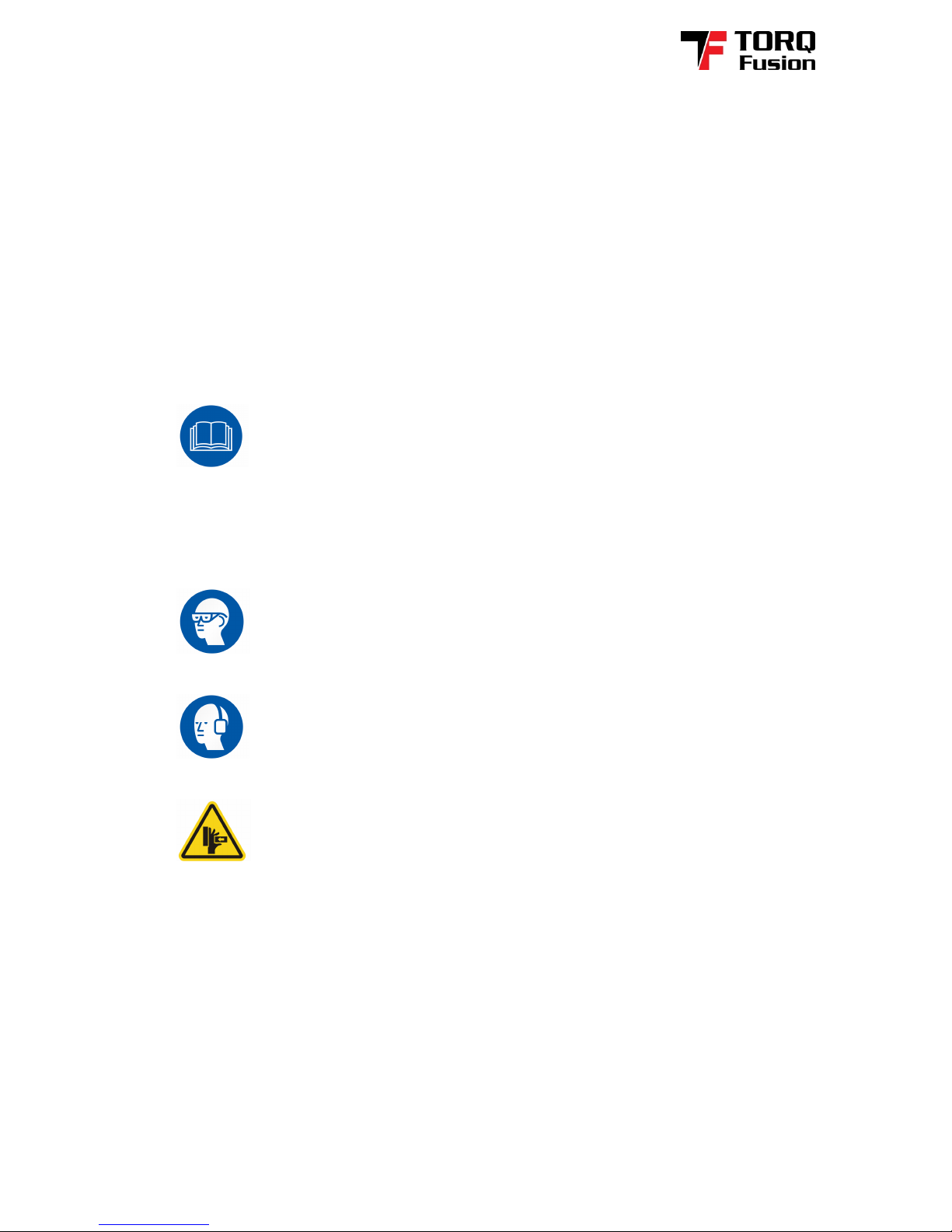
PPE – (Personal Protective Equipment)
Always wear protective eyewear when operating power
tools or entering an industrial environment.
Always wear hearing protection when operating power
tools or environmental conditions may exceed 85 dB(A) of noise.
Never place your hands or other body parts near the
reaction arm or any moving component – avoid pinch points.
It is a good practice to also wear wor gloves, a hard hat, steel toe
shoes and any other protective equipment suitable for the tas
being performed. Please consult with your company’s safety
advisor for more information.
Table of contents
Popular Nail Gun manuals by other brands

Metabo HPT
Metabo HPT NR 3675DD Instruction and safety manual

EXTOL PREMIUM
EXTOL PREMIUM 8894580 Translation of the original user manual

DeWalt
DeWalt XR Li-Ion DCN680D2 Original instructions

Performance Tool
Performance Tool M643 owner's manual

Hitachi
Hitachi VH650 - Fencing Nailer, Full Head instruction manual

Parkside
Parkside PET 25 B1 Operation and safety notes


