TORXUN AUTOPED M10S.0039 User manual

Autoped Installation Manual rev 2.0 (100722)1
AUTOPEDTM OPERATOR
INSTALLATION MANUAL
©2022

Autoped Installation Manual rev 2.0 (100722)2
TORXUN reserves the right to make changes in the products described in this manual without notice and without obligation of TORXUN
to notify any persons of any such revisions or changes. Additionally, TORXUN makes no representations or warranties with respect to
this manual.
This manual is copyrighted 2022 TORXUN Vehicle Access Systems, all rights reserved.
No portion of this manual may be copied, reproduced, translated, or reduced to any electronic or digital medium without prior
written consent from TORXUN.

Autoped Installation Manual rev 2.0 (100722)3
TABLE OF CONTENTS
WELCOME LETTER FROM ART HIRD ……………………………………………………………………………………….……
7
AUTOPED PARTS AND COMPONENTS………………………………………………………………………………….………..
8
PARTS/COMPONENT LIST AND DESCRIPTIONS ………………………………………………………………………...
8
IMPORTANT INSTALLATION NOTES ……………………………………………………………………………………………...
9
A. AUTOPED CONVERSION: LEFT-HAND TO RIGHT-HAND (OR VICE VERSA) ……………………………………
9
B. AUTOPED ARM TYPES: PUSH ACTION (STANDARD ARM) OR PULL ACTION (TRACK ARM) ……………...
10
C. GENERAL REQUIREMENTS FOR INSTALLING THE AUTOPED ……………………………………………………
11
D. RECOMMENDED TOOLS FOR INSTALLATION ………………………………………………………………………..
11
SECTION I. INSTALLING THE AUTOPED ON HEADERS 4” OR BIGGER …………………………………………………
12
I.1 INSTALLATION: LEFT-HAND MOUNTED AUTOPED …………………………………………………………………
13
I.2 INSTALLATION: RIGHT-HAND MOUNTED AUTOPED ……………………………………………………………….
14
SECTION II. INSTALLING THE AUTOPED ON HEADERS SMALLER THAN 4”…………………………………………...
15
II.1 INSTALLATION: LEFT-HAND MOUNTED AUTOPED ………………………………………………………………..
16
II.2 INSTALLATION: RIGHT-HAND MOUNTED AUTOPED ………………………………………………………………
17
SECTION III. INSTALLING THE STANDARD ARM ASSEMBLY (P/N: M10S.0028) ………………………………………...
18
III.1INSTALLATION: STANDARD ARM ASSEMBLY………………………………………………………………..…..…
19
SECTION IV. INSTALLING THE TRACK ARM ASSEMBLY (P/N: M10S.0039) ……………………………………………...
22
IV.1 INSTALLATION: CONFIGURING THE AUTOPED FOR PULL ACTION ……………………….……………..…...
23
IV.2 INSTALLATION: TRACK ARM ASSEMBLY……………………………………………………………………..……..
24

Autoped Installation Manual rev 2.0 (100722)4
SECTION V. INSTALLING THE 3-FUNCTION ROCKER SWITCH (OR OPTIONAL KEY SWITCH) ………………………
26
V.1 INSTALLATION: 3-FUNCTION ROCKER SWITCH .…………………………………………........………………….
27
SECTION VI. CONNECTING THE AUTOPED TO AC POWER SOURCE …………………………………………………….
29
VI.1 CONNECTING TO 115 VAC POWER SOURCE …………………………………………………………………….
30
SECTION VII. INSTALLING THE OPTIONAL POSITIVE STOP (P/N: M10S.0040) ………………………………………….
31
VII.1 THE POSITIVE STOP KIT ……………………………………………………………………………………………….
32
VII.2 INSTALLING THE POSITIVE STOP ……………………………………………………………………………………
32
SECTION VIII. CLOSING-SPRING PRELOAD ……………………………………………………………………………….…...
34
VIII.1 ADJUSTING THE CLOSING - SPRING LOAD ..………………………………………………………………………
35
SECTION IX. INSTALLING DOUBLE DOOR AND INTERLOCK SALLY PORT CONFIGURATIONS ………...…………
36
IX.1 SETUP SEQUENCE FOR DOUBLE DOOR/GATE OPERATION ………………………………..……………..…...
37
IX.2 SETUP SEQUENCE FOR INTERLOCK/SALLY PORT AIRLOCK …………………………………………………..
39
SECTION X. INSTALLING ELECTRIC LOCKS, STRIKES AND SAFETY/ACCESS CONTROL DEVICES ………….….
40
X.1 ELECTRIC LOCKS AND STRIKES SETUP …………………………………………………..………………………...
41
SECTION XI. QUICK START PROGRAMMING ………………………………………………………………………………….
42
XI.1 PROGRAMMING FLOW GUIDE CHART …………………………………………………..………………………...
43
XI.2 PROGRAMMING SEQUENCE FOR SINGLE DOOR/GATE OPERATION …………..…………………………….
41
XI.3 ADDITIONAL PROGRAMMING OPTIONS ……………………………………………..……………………………...
48
XI.4 FINAL ADJUSTMENTS AND COMPLIANCE TO ANSI 156.19 ……………………………...………………………
48
XI.5 REATTACH CONTROL BOX COVER AND OPERATOR FRONT COVER…………………………………………
49

Autoped Installation Manual rev 2.0 (100722)5
SECTION XII. MENUS AND PROGRAMMING …………………………………………………………………………………...
50
XII.1 MENU GLOSSARY ………..………………………...……………………………………….…………………………..
51
XII.2 CONTROL UNIT LED LIGHTS ……………...………………………………...…………….…………………………..
51
XII.3 LCD SCREEN GLOSSARY ……………………...…………………………………..….………………………………
51
XII.4 CHART FOR MENUS AND WHAT THEY DO .…………………………………………….………………………….
52
XII.5 PARAMETER MENU: SETTINGS FOR DOOR/GATE MOVEMENT ………………………………………..…...…
52
XII.6 CONFIGURATION MENU OPTIONS AND DEFINITIONS .……………………………………………………….....
55
XII.7 DOUBLE DOOR MENU CHART ………………………………………………………………...…………………..….
56
XII.8 DIAGNOSTIC TABLE ……………………………………………………………………………………...……………..
56
XII.9 REINIT MENU (RESET BACK TO FACTORY DEFAULT) ……………………………..……………...…..……..….
57
XII.10BLOCK/UNBLOCK MENU: LOCK KEYS ………………………………………………….……………….………...
57
XII.11TEACH MENU ……...………………………………………………………………………….……………………...…
58
SECTION XIII. TROUBLE SHOOTING AND ERROR CHARTS ……………………………………………………………….
59
XIII.1 ERROR CODE DEFINITIONS …………………………………………………………………………………………
60
SECTION XIV. TERMINAL CONNECTIONS AND WIRING SCHEMATICS …………………………………………………..
65
XIV.1 TERMINAL CONNECTION CHART ………………………………………………………….………………………..
66
XIV.2 WIRING SCHEMATIC DIAGRAMS ……………………………………………………….…………………………...
68
SECTION XV. SERVICE PARTS ……………………………………………………………………………………………………
77
XV.1 SERVICE PARTS/COMPONENTS VISUAL GUIDE ……….…….…………….…………………………………….
78
XV.2 STANDARD PARTS LIST …………………………………………..……………….…………………………………..
79
XV.3 OPTIONAL PARTS LIST ……………………………………………..……………….…………………………………
79
SECTION XVI. PRODUCT WARRANTY AND REGISTRATION ……………….………….………………………………….
80
XVI.1 TORXUN LIMITED WARRANTY……………………………………………...………...……………………………...
81
XIV.2 PRODUCT REGISTRATION …………………………………………………………………….……………………..
82

Autoped Installation Manual rev 2.0 (100722)6
The above QR code will takeyou to a video demonstration of an AutoPed installation performed by Torxun.
The video demonstrates a basic installation with a Standard PushArm Assembly (P/N: M10S.0028).

Autoped Installation Manual rev 2.0 (100722)7
Welcome - thank you for your purchase! Our commitment to quality and innovation will become evident as you become
familiar with the features, performance, and easy installation of this expertly engineered AutoPed heavy duty pedestrian swing
Door/Gate operator.
Some of its features are:
oFully outdoor rated
oBuilt for continuous, heavy duty use for gates up to 250 lbs and 63”wide
oUL 325 listed and designed to meet ANSI 156.19 low energy operated swinging door standards
oA single model works for left and right-hand door/gates and push and pull applications
Installers - I love you folks! I have been installing gate systems for decades. We have organized these instructions to keep
things simple. This manual contains the instructions to install the AutoPed on a variety of header structures. You will find a
“Quick Start Programming”in Section XI to get the AutoPed up and running its basic functions. Whenyou needthe AutoPed to
perform its more complex functions and features, this manual provides you the additional “Menus and Programming”in Section XII.
Throughout, we will point you right to the section to which you need to refer.
Be safe! - think about your own safety during the installation. Also think about the safety of the public who will be using this
automated gate for years to come. You NEED to be familiar with ANSI 156.19 standards. It is your responsibility to install and
program the AutoPed to comply with these standards which include the velocity of the gate-in-motion, the force of the gate
panel and the safety/warning labels. This manual will remind you of these responsibilities, but at the end of the day, you are
the one in the field and are responsible for the publics’ safety!
Options - some installations will require optional parts that you will need to order from your distributor to complete your
installation. Refer to Section XV for AutoPed’s standard and optional parts components before you head out to install to confirm
you have what you need.
Owner/User - you are in for a treat! This operator is going to bring the satisfaction of automation to your property making
residents and users happy that life has gotten just a little easier. Safety first! Please make sure that someone is responsible
for daily checks of the gate system. For service, use only qualified and trained technicians.
I want you to love this AutoPed Operator. I have been in this industry since 1976 and have never stopped trying to make
products better. So let me know what you would like improved... AND what you appreciate.
Art Hird, President
Autoped Installation Manual rev 2.0 (100722)8
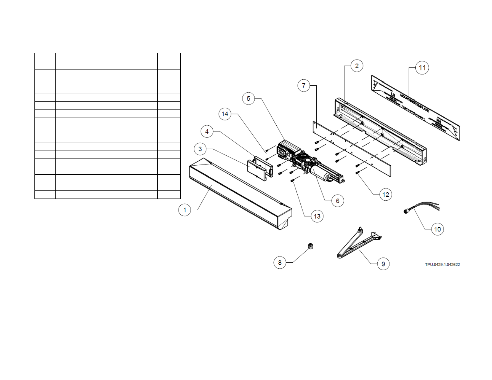
AUTOPED OPERATOR STANDARD PARTS AND COMPONENTS
Item
Description
Qty
1
Enclosure - Front Cover
1
2
Enclosure - Rear Cover
(Chassis)
1
3
Control Unit Cover - Front
1
4
Control Unit Cover - Rear
1
5
Control Unit
1
6
Motor-Gearbox Assembly
1 set
7
Assembly Plate
1 set
8
Spindle Extension; 20MM
1
9
Standard Arm Assembly
1
10
3-Function Rocker Switch
1 set
11
Mounting Template
1
12
Assembly Plate Mounting
Screws
6
13
Motor-Gearbox Assembly
Mounting Screws
4
14
Control Unit Mounting Screws
2

Autoped Installation Manual rev 2.0 (100722)9
IMPORTANT INSTALLATION NOTES
A. CONVERSION: LEFT-HAND INSTALLATION TO RIGHT-HAND INSTALLATION (or vice versa)
The AutoPed operator can be used in a left-hand or right-hand, push or pull door/gate system application without need for
conversion adapters or modification. To change the Hand of the Operator Installation:
•Remove the motor-drive assembly attached to the assembly plate from the chassis by removing the
six (6) M6x12 bolts; Fig 1
•Rotate the assembly plate with the motor-drive clockwise or counter-clockwise to facilitate
either left- or –right-hand installation.
•Chassis is neutral, Orientation is the same for left- or right- hand installation
•Left-hand operator installation: Control unit is to the left of the motor-drive
•Right-hand operator installation: Control unit is to the right of the motor-drive
Fig I.1 Changing Operator Installation: Left-hand to Right-hand or vice versa

Autoped Installation Manual rev 2.0 (100722)10
B. AUTOPED ARM TYPES: PUSH ACTION (STANDARD ARM); PULL ACTION (TRACK ARM)
B.1 Push Action –Standard Arm Assembly; P/N M10S.0028
If the required operation is “push open”the Door/Gate, the AutoPed is fitted with a Standard Arm; Fig B.1
Note that in this configuration, the door hinge is located on the side of the door frame opposite the location of the AutoPed.
When the AutoPed is energized, the Standard Arm “pushes”to swing the door or gate open away from the AutoPed.
B.2 Pull Action –Track Arm Assembly; P/N M10S.0039
If the required operation is to “pull open”the Door/Gate, the AutoPed is fitted with the Track Arm; Fig B.2
Note that in this configuration, the door hinge and the AutoPed are both located on the same side of the door frame. When
the AutoPed is energized, the Track Arm “pulls”to swing the door or gate open from under the AutoPed.
Fig B.1 Standard Arm
Fig B.2 Track Arm

Autoped Installation Manual rev 2.0 (100722)11
C. GENERAL REQUIREMENTS FOR INSTALLING THE AUTOPED
1. Important: The AutoPed requires that the Door/Gate rest against some type of actual stop in the closed position. The unit will self-
check the closed limits by attempting to close past the closed limit. If the unit does not sense the resistance of a stop, a locking device,
or a door jamb, etc., the AutoPed will go into a soft shutdown.
2. The AutoPed cannot be installed on a Double acting door: a door that swings both in and out.
3. TORXUN recommends installing the AutoPed on Door/Gate headers measuring four inches (4”) or more in height.
4. For installation on headers less than four inches (4”) in height, TORXUN requires the use of the StiffenerPlate or equivalent to add
rigidity to the installation of the operator; refer to Sections II.1 and II.2.
D. RECOMMENDED TOOLS FOR INSTALLATION
•Hammer
•Center punch set
•Portable power drill and bits (1/16”, 1/8”)
•Micro flat head screwdriver
•Flat head screwdriver ( 2mm)
•Philips head screwdriver #1
•3mm Allen key
•5mm Allen key
•6mm Allen key
•Wire stripper
•Level gauge
•Wire nuts 22~14 gauge
•Masking tape
•Ladder or step stool
•Zip ties

Autoped Installation Manual rev 2.0 (100722)12
SECTION I
INSTALLING THE AUTOPED
ON HEADERS 4”OR BIGGER
Autoped Installation Manual rev 2.0 (100722)13
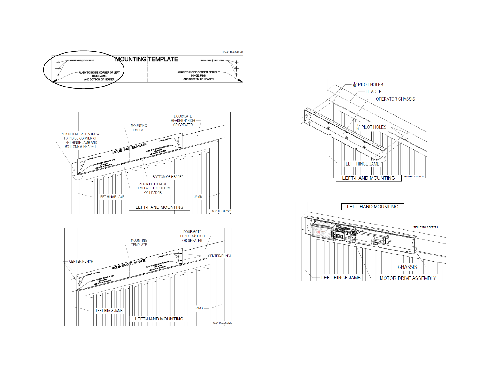
I.1 INSTALLATION: LEFT-HAND MOUNTED AUTOPED ON HEADERS 4”OR BIGGER
STEP 1 Use left-hand side of Mounting Template
STEP 2 Align arrow to inside corner of left hinge jamb and
bottom of header
STEP 3 Center-punch mounting holes through Template
STEP 4 Drill 1/16” pilot holes on header through
Template
STEP 5 Mount
1
operator Chassis directly to header
STEP 6 Mount
2
Motor-Drive assembly to operator Chassis
STEP 7 Proceed to Section III or IV to continue installation of the
swing arm assembly
1
Type, size and material of fastener by installer
2
Use Screw M6 x 1.0 x 12 included in kit

Autoped Installation Manual rev 2.0 (100722)14
I.2 INSTALLATION: RIGHT-HAND MOUNTED AUTOPED ON HEADERS 4”OR BIGGER
STEP 1 Use right-hand side of Mounting Template
STEP 2 Align arrow to inside corner of right hinge jamb and
bottom of header
STEP 3 Center-punch mounting holes through Template
STEP 4 Drill 1/16” pilot holes on header through Template
STEP 5 Mount
3
operator Chassis directly to header
STEP 6 Mount
4
Motor-Drive assembly to operator Chassis
STEP 7 Proceed to Section III or IV to continue installation of the
swing arm assembly
3
Type, size and material of fastener by installer
4
Use Screw M6 x 1.0 x 12 included in kit

Autoped Installation Manual rev 2.0 (100722) 15
SECTION II
INSTALLING THE AUTOPED
ON HEADERS SMALLER THAN 4”
For installation of the AutoPed on headers less than four inches (4”) in height,
TORXUN requires the use of the StiffenerPlate (P/N: M10S.011) or its equivalent to
add rigidity to the installation of the operator.

Autoped Installation Manual rev 2.0 (100722) 16
II.1 INSTALLATION: LEFT-HAND MOUNTED AUTOPED ON HEADERS LESS THAN 4”
STEP 1 Put up the StiffenerPlate on the header
STEP 2 Align the StiffenerPlate to the corner of the left
hinge jamb and bottom of header; marked “X”on
the drawing
STEP 3 Center-punch pilot holes 1,2,3
STEP 4 Drill 1/16” pilot holes 1,2,3
STEP 5 Fasten
5
StiffenerPlate through holes 1,2,3
STEP 6Mount
6
operator Chassis to StiffenerPlate
STEP 7Mount
7
Motor-Drive assembly to operator Chassis
STEP 8 Proceed to Section III or IV to continue installation of the
swing arm assembly
5
Type, size, and material of fasteners by installer
6
Use screws NF 7/16 x 20 x 3/4 included in kit to mount
7
Use screws M6 x 1.0 x 12 included in kit to mount

Autoped Installation Manual rev 2.0 (100722) 17
II.2 INSTALLATION: RIGHT-HAND MOUNTED AUTOPED ON HEADERS LESS THAN 4”
STEP 1 Put up the StiffenerPlate on the header
STEP 2 Align the StiffenerPlate to the corner of the right
hinge jamb and bottom of header; marked “X”on
the drawing
STEP 3 Center-punch pilot holes 1,2,3
STEP 4 Drill 1/16” pilot holes 1,2,3
STEP 5 Fasten
8
StiffenerPlate through holes 1,2,3
STEP 6 Mount
9
operator Chassis to StiffenerPlate
STEP 7 Mount
10
Motor-Drive assembly to operator Chassis
STEP 8 Proceed to Section III or IV to continue installation of the
swing arm assembly
8
Type, size, and material of fasteners by installer
9
Use screws NF 7/16 x 20 x 3/4 included in kit to mount
10
Use screws M6 x 1.0 x 12 included in kit to mount

Autoped Installation Manual rev 2.0 (100722) 18
SECTION III
INSTALLING THE
STANDARD ARM ASSEMBLY
(PUSH ACTION OPERATION)
P/N: M10S.0028
Autoped Installation Manual rev 2.0 (100722) 19
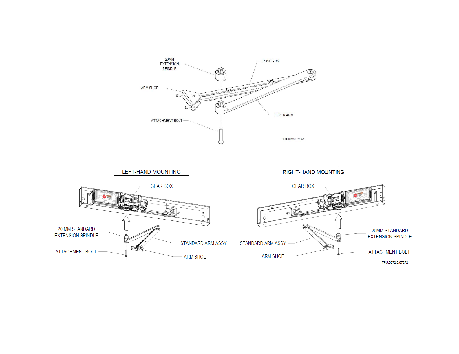
III.1 INSTALLATION: STANDARD ARM ASSEMBLY
STEP 1 Assemble the Standard Arm Assembly
STEP 2 Insert Standard Arm assembly with 20MM standard Extension Spindle to the Operator Gear Box
NOTE: 30mm (M10S.0018) and 50mm (M10S.0055) Spindle Extension are available as optional parts
ordered separately. If needed, it may be used instead of the 20mm to lower further the Standard
Arm assembly to accommodate wider clearance/gap between bottom of AutoPed operator and
top of Arm Shoe.
Autoped Installation Manual rev 2.0 (100722) 20
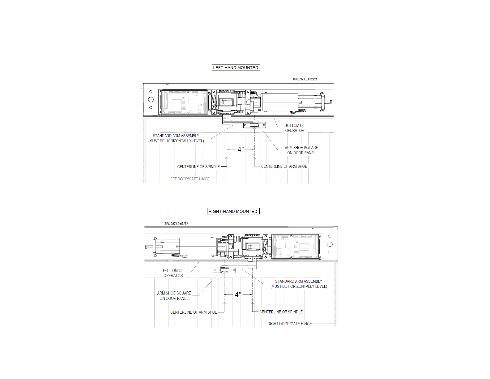
STEP 3 Sit the Arm Shoe squarely on the face of the Door/Gate frame (or panel)
STEP 4 For a left-hand mounted AutoPed, place centerline of Arm Shoe 4” to the right of the centerline of spindle.
For a right-hand mounted AutoPed, place centerline of Arm Shoe 4” to the left of the centerline of spindle.
NOTE: Make sure the Standard Arm is inserted to the Gear Box snugly and installed level.
This manual suits for next models
1
Table of contents
Popular Door Opening System manuals by other brands

Schartec
Schartec Prime 600 Installation and operating instructions

SOMFY
SOMFY Yslo Flex 2 RTS installation guide

Prismatibro
Prismatibro Prisma Button 800 installation manual

Assa Abloy
Assa Abloy Yale 3000 Series installation instructions

Dormakaba
Dormakaba 8900 T installation instructions

FAAC
FAAC A951 quick start


