manuals.online logo
Brands
  1. Home
  2. •
  3. Brands
  4. •
  5. Lamp
  6. •
  7. Door Opening System
  8. •
  9. Lamp KF111-H User manual

Lamp KF111-H User manual

1
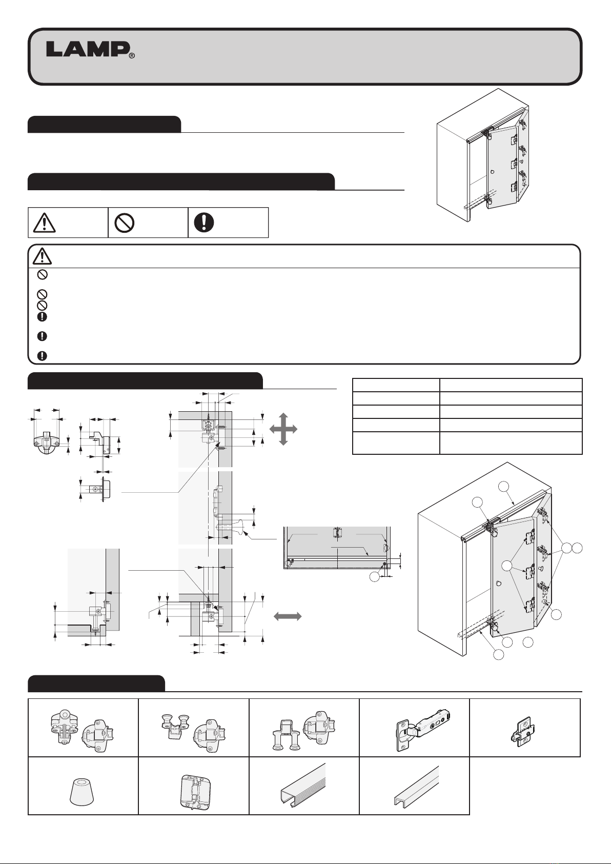
KF111-H FOLDING DOOR SYSTEM
Installation Manual
Door Width Max. 450 mm per door
Door Height Max. 2400 mm
Door Thickness 18-30 mm
Door Weight Max. 10 kg per door
Coverage Max. 26 mm
(with Sugatsune H360 hinge)
1
8
9
7
4 5
2 3
or
6
5mm
5m
m
8mm
17 16 15
32.5 15
3
φ40
6.5
59
48
24
Min80
8
Min36
4.5
27.5 2
(7)
(10)
22 13
8
15
32
22 13
3216
45
38
34
14
26
φ40
42
24
16
12
18
Adjustment
UpperRollerHinge
Knob
(Option)
LowerRollerHinge
Adjustment
Lowerroller-L
(Recessed)
Lowerroller-S
(Undermount)
Example of
“Lower - Roller - S”
Thank you for selecting our product. Before starting installation, please read this manual
thoroughly to ensure correct installation. Please keep this manual at hand for future reference.
・This product is parts set for installation of folding door system for cabinets.
・The rails can be hidden by the overlay door panels.
ABOUT THIS PRODUCT
FOR YOUR SAFE WORK AND CORRECT INSTALLATION
INSTALLATION DRAWING (EXAMPLE)
COMPONENT PARTS
Min40
Min
17
Side boardSide board
Bottom board
 6
⑥Stopper
①Upper roller
FD111-TRH
②
Lower roller - S FD111-BRSH
③
Lower roller - L FD111BRLH
④Concealed hinge H360-26-26T
⑤
Mounting plate 360-P4W-32T
⑥Stopper K-2017 ⑦Center Hinge CH-75 ⑧Upper rail ⑨Lower rail
Hinge part Hinge part Main body
Main body
Main body Hinge part
Caution :
Prohibited
Warning
Caution Required
Meaning of symbols
If not followed, it may result in injury or damage.
Provide a cabinet that can withstand the weight and impact of opening and closing the door. Be sure to use the specified screws and tighten them securely.
If the mounting strength is insufficient, the door may fall and cause injury.
Do not disassemble or modify any parts other than those described in this document.
Follow the specified dimensions, specifications, and alignment of the cabinet. Warping, tilting or twisting of the cabinet or door may cause failure.
Make sure to follow the designated measurements and specifications as well as horizontal and verticals angles. Make sure that the cabinet is not warped,
since it may affect the movement of the door.
This product is a part for furniture. After installation, please check the function and safety of the final product. Please inform the end user how to use the
product safely.
Make sure to check the screws for slack at regular intervals (one month from first usage, half a year, and then one time every year is recommended).
2
The drawing describes the right handed opening type.
The left-handed opening type is a mirror image.
Cutting rails
1Installing upper rail
2
Application
Hinged door at 90°open Hinged door at 95°open Other door at 87.5°open
2 Doors folding
W = Width of inside cabinet
W1= Width of door ①and ④
W2= Width of door ②and ③
W3= Width of door ③′
E = Coverage
θ° = Opening angle at hinged door
W1= W + 2E - 3.3
2
W2= W1+ 1.7
W1= W + 2E - 6.8
2
W2= W1+ 5.2
W1= W + 2E - 1.6
2
W2= W1
2 Doors folding and 1 swing open W3= W1
W1= W + 2E - 7.3
3
W2= W1+ 1.7
W3= W1
W1= W + 2E - 10.8
3
W2= W1+ 5.2 W1= W + 2E - 5.6
3
W1= W2= W3
W3= W2
W1= W + 2E - 9
3
W2= W3= W1+ 1.7
W3= W2
W1= W + 2E - 16
3
W2= W3= W1+ 5.2
2 Doors folding and 2 Doors folding
W1= W + 2E - 10.6
4
W2= W1+ 1.7
W1= W + 2E - 17.6
4
W2= W1+ 5.2
W1= W + 2E - 7.2
4
W1= W2
E
E
1.6
W2
W3W1
W
Min. 4
E
E
1.6
1.6
W2
W
W1
W2
W1
Min. 4
E
W2
E
1.6
W1
W
Door Hinge
2Door 1
Hinge Hinge
Door 2 1
Hinge Hinge
4 3 Door 2Door 1
θ°
θ°
θ°
θ°θ°
3
Required Parts
Door Height
Concealed hinge ④
Mounting plate ⑤
(pcs)
Center hinge ⑥
(pcs)
900 mm 2 3
1600 mm 3 3
2000 mm 4 4
2400 mm 5 4
Coverage at
Hinge door side
C1-
Dimension
C2-
Dimension
22 mm 4 mm 5 mm
23 mm 5 mm 6 mm
24 mm 6 mm 7 mm
25 mm 7 mm 8 mm
26 mm 8 mm 9 mm
Opening clearance for Hinge door side
C1
(mm)
Door thickness (mm)
18 22 26 30
4 0.1 0.5 1.2 5.0
5 0.1 0.5 1.2 4.0
6 0.1 0.5 1.1 3.0
7 0.1 0.5 1.1 2.1
8 0.1 0.5 1.1 2.0
Knob Installation (Sold separately)
Recommended knob mounthing position Ⓐfor opening & Ⓐ′ for closing the door.
Install one knob at Ⓑposition is also applicable for both opening & closing.
12
25
32
E2
FE1
φ40 x 15
34 42
32
C1C2
Min 60 Min 70
Hinge door side
Min
60
Min
70
Approx
40
Approx
40
φ40 x 15
A B A
Position for
Mounting plate
Cut Upper rail & Lower rail to the required length.
Length = W - 1.5
Insert Upper roller to Upper
rail before mounting.
Upper rail
Upper roller
E1= Coverage (top)
E2= Coverage (bottom)
F = Gap between door bottom and oor (10mm)
CABINET / DOOR WIDTH DIMENSIONS
DOOR PROCESS DIMENSION
INSTALLATIOIN PROCEDURE
Remove any dirt or aluminum chips from the rail
as they would cause noise during operation.
Causion
When installing the rails, ensure that upper rail
and lower rail are parallel.
Causion
3
Installing knob
As for the position of the knob, please refer to "Door
Process Dimensions" on page 2 and
"How to operate the knob" on page 4.
5
Hanging the doors
Put a support of suitable height under the doors, clip on the
hinges on the door to the mounting plates on the cabinet.
8
Checking the door movement
Open and close the door for several time and check
if the door moves smoothly. Then re-tighten the xing
screws of all parts.
13
Installing concealed hinges, upper roller
Install Concealed hinge for Pivot side door.
Install the hinge of Sliding guide for moving door.
3
Installing center hinges
4
Countersunkheadtappingscrew
4x16(Notincluded)
Springcase
Inside
Outside
Pivotsidedoor Fitthispartonthedoor.
Fixthescrewswhilepushing
theMovingdoor.
Pivotsidedoor Movingdoor
STEP 1 : Mount the hinge on
the Pivot side door
STEP 2 : Fix the Moving door
Fixing the mounting plates for Pivot side
door
7
Door adjustment
9
Installing Upper roller
Topboard
Upperroller①
Movingdoor
Adjustscrew
Screwdriver
Fixingscrew
Reference
pisition
(1) Insert Hinge part in
the socket part of
Upper roller, while
adjusting the height.
(2) Tighten the xing
screw temporarily
at the reference
position.
Installing Lower roller
11
10
Bottom board Moving
door
Lower roller - S ②
Under mount
Bottom board
Moving
door
Recessed mount
Fixing screw
Reference pisition
(1) Insert Lower roller in the
Lower rail.
(2) Insert Hinge part in the
socket part of Lower roller.
(3) Tighten the xing screw
temporarily at the
reference position.
Raised countersunk head tapping
screws 3.5 ×15 (Not included)
Pivot side door
(Rear surface)
90°
Side
board
Top
board
Door
Forward
Up
Right
Left
Down
1
3
2
Top
board
Side
board
Door
Backward
1
2
3
Side
board
Top
board
Door
Forward
Up
Right
Left
Down
1
3
2
1
2
3
Top
board
Side
board
Door
Backward
Assembling door panels
Couple the hinge
parts as shown
in the right gure,
then insert the
hinge pin from
above.
12
Pin
Pivot side door
Moving door
Separating door panels
Pull out the pin from
center hinge as shown
in the below gure.
6
Pin
Mounting plate ⑤
Raised countersunk head tapping
screws 3.5 x 15 (Not included)
a
P1
P2
P1
a
P2
Pivot side door
(Rear surface)
Periodically check if all of the screws are not loose.
If the looseness is found, tighten it.
Causion
4
How to closeHow to open
Two knobs
One knob
Moving
door
Pivot side
door
B
A
Side
board
Pivot side
door
Moving
door
B
A
OK
OKOK
〈1〉
〈2〉
〈3〉
A =B A >B
When the door is inclined a lot like the right illustration,
adjust the door by the adjustment screws on the concealed
hinges. Do not try to adjust it by the screws on the sliding
guide.
There are three ways of adjustment as below..
〈1〉Reduce the upper gap by the top and middle hinges.
〈2〉Reduce the upper gap by the top hinge and increase
the lower gap by the bottom hinge.
〈3〉Increase the lower gap by the bottom hinge.
Adjust the fore-and-aft position of the concealed hinges so
that the both A and B gaps are the same.
How to closeHow to open
Two knobs
One knob
Moving
door
Pivot side
door
B
A
Side
board
Pivot side
door
Moving
door
B
A
OK
OKOK
〈1〉
〈2〉
〈3〉
A =B A >B
If "A" is bigger than "B", the closing action would not be
smootht. Re-adjust the gaps as below.
1. Loosen all fore-and-aft-adjustment screws on the
concealed hinges, and reduce the gap A, then re-tighten
the screws.
2. If "A" is still bigger "B", increase the gap B by ajusting
the screws on the sliding guides.
ADJUSTMENT OF THE INCLINED DOOR
SUGGESTIONS FOR DOORS IN EQUAL WIDTH
HOW TO OPERATE THE KNOB
SUGATSUNE KOGYO CO.,LTD  
Tokyo, JAPAN
Phone: +81 (0)3 3866 2260 E-mail:[email protected]
SUGATSUNE KOGYO (UK) LTD  
Reading, UK
Phone: +44 118 9272 955
 
E-mail:[email protected]
SUGATSUNE EUROPE GmbH  
Dusseldorf, GERMANY
Phone: +49 211 53812900
 
E-mail:[email protected]
SUGATSUNE SHANGHAI Co., LTD  
Shanghai, CHINA
Phone: +86 21 3632 1858  E-mail:[email protected]
Guangzhou, CHINA  
Phone: +86 20 6639 3552  E-mail:[email protected]
SUGATSUNE KOGYO INDIA PRIVATE LIMITED  
Mumbai, INDIA
Phone: +91 22 28314490/91 E-mail:[email protected]
SUGATSUNE AMERICA, INC  
California, USA
Phone: +1 310 329 6373 E-mail:[email protected]
Chicago, USA  
Phone: +1 312 461 1081
E-mail:[email protected].
SUGATSUNE CANADA, INC.  
Phone: +1 514 312 5267
E-mail:[email protected]
2021.06 0805-5

Other Lamp Door Opening System manuals

Lamp FD30EX User manual

Lamp

Lamp FD30EX User manual

Lamp FD80-H User manual

Lamp

Lamp FD80-H User manual

Lamp HDSN-30K User manual

Lamp

Lamp HDSN-30K User manual

Lamp FD35EV User manual

Lamp

Lamp FD35EV User manual

Lamp FD50-H User manual

Lamp

Lamp FD50-H User manual

Lamp FD35EV User manual

Lamp

Lamp FD35EV User manual

Lamp FD80-AFH User manual

Lamp

Lamp FD80-AFH User manual

Lamp FD35EV User manual

Lamp

Lamp FD35EV User manual

Lamp KF28 User manual

Lamp

Lamp KF28 User manual

Lamp HC-70 User manual

Lamp

Lamp HC-70 User manual

Lamp FD30-F User manual

Lamp

Lamp FD30-F User manual

Lamp FD35EV User manual

Lamp

Lamp FD35EV User manual

Lamp AZ-AT230-HL Instruction Manual

Lamp

Lamp AZ-AT230-HL Instruction Manual

Lamp XL-GC07D-CR User manual

Lamp

Lamp XL-GC07D-CR User manual

Lamp FD30EX User manual

Lamp

Lamp FD30EX User manual

Lamp Lapcon J160 User manual

Lamp

Lamp Lapcon J160 User manual

Lamp SLUN-N User manual

Lamp

Lamp SLUN-N User manual

Lamp FD50-H User manual

Lamp

Lamp FD50-H User manual

Lamp FD30-F User manual

Lamp

Lamp FD30-F User manual

Lamp LDD-S User manual

Lamp

Lamp LDD-S User manual

Lamp FD50-H User manual

Lamp

Lamp FD50-H User manual

Lamp HCZ-80 User manual

Lamp

Lamp HCZ-80 User manual

Lamp AZ-GD231 User manual

Lamp

Lamp AZ-GD231 User manual

Lamp MonoFlat FAD-5 User manual

Lamp

Lamp MonoFlat FAD-5 User manual

Popular Door Opening System manuals by other brands

Dorex 1900 Series installation instructions

Dorex

Dorex 1900 Series installation instructions

Design Hardware F1000V Series installation instructions

Design Hardware

Design Hardware F1000V Series installation instructions

Assa Abloy SW100 user manual

Assa Abloy

Assa Abloy SW100 user manual

Mhouse GD0 Installation instructions and warnings

Mhouse

Mhouse GD0 Installation instructions and warnings

Detex AO19-1 manual

Detex

Detex AO19-1 manual

Genie GCL-LT manual

Genie

Genie GCL-LT manual

Assa Abloy Norton 1600 UniTrol quick start guide

Assa Abloy

Assa Abloy Norton 1600 UniTrol quick start guide

Genius MIDEL22 installation instructions

Genius

Genius MIDEL22 installation instructions

Eco SR-EF BG TS-41 G Assembly instruction

Eco

Eco SR-EF BG TS-41 G Assembly instruction

BFT VIRGO installation manual

BFT

BFT VIRGO installation manual

Dormakaba EN 2-5 Mounting instructions

Dormakaba

Dormakaba EN 2-5 Mounting instructions

Becker a100/25 Assembly and operating instructions

Becker

Becker a100/25 Assembly and operating instructions

MOTION4 EvoDrive+ Maintenance manual

MOTION4

MOTION4 EvoDrive+ Maintenance manual

Dorma ES 200 Easy Mounting instruction

Dorma

Dorma ES 200 Easy Mounting instruction

Stanley Hardware V8177 installation instructions

Stanley Hardware

Stanley Hardware V8177 installation instructions

BFT VISTA SW 260 SXL user manual

BFT

BFT VISTA SW 260 SXL user manual

Eco EF TS-41 Assembly instruction

Eco

Eco EF TS-41 Assembly instruction

Dorma PORTEO Assembly instruction

Dorma

Dorma PORTEO Assembly instruction

manuals.online logo
manuals.online logoBrands
  • About & Mission
  • Contact us
  • Privacy Policy
  • Terms and Conditions

Copyright 2025 Manuals.Online. All Rights Reserved.