BFT TELEC MA User manual

TELEC MA
D811266 23-09-00 Vers. 02
AUTOMATION
FOR SPRING
OVERHEAD DOORS

287
1) GENERAL SAFETY
WARNING! An incorrect installation or improper use of the product
can cause damage to persons, animals or things.
•The “Warnings”leaflet and “Instruction booklet”supplied with this
product should be read carefully as they provide important information
about safety, installation, use and maintenance.
•Scrap packing materials (plastic, cardboard, polystyrene etc) according
to the provisions set out by current standards. Keep nylon or polystyrene
bags out of children’s reach.
•Keep the instructions together with the technical brochure for future
reference.
•This product was exclusively designed and manufactured for the use
specified in the present documentation. Any other use not specified in
this documentation could damage the product and be dangerous.
•The Company declines all responsibility for any consequences resulting
from improper use of the product, or use which is different from that
expected and specified in the present documentation.
•Do not install the product in explosive atmosphere.
•The construction components of this product must comply with the
following European Directives: 89/336/CEE, 73/23/EEC, 98/37/EEC
and subsequent amendments. As for all non-EEC countries, the above-
mentioned standards as well as the current national standards should
be respected in order to achieve a good safety level.
•The Company declines all responsibility for any consequences resulting
from failure to observe Good Technical Practice when constructing
closing structures (door, gates etc.), as well as from any deformation
which might occur during use.
•The installation must comply with the provisions set out by the following
European Directives: 89/336/CEE, 73/23/EEC, 98/37/EEC and
subsequent amendments.
•Disconnect the electrical power supply before carrying out any work on
the installation. Also disconnect any buffer batteries, if fitted.
•Fit an omnipolar or magnetothermal switch on the mains power supply,
having a contact opening distance equal to or greater than 3mm.
•Check that a differential switch with a 0.03A threshold is fitted just before
the power supply mains.
•Check that earthing is carried out correctly: connect all metal parts for
closure (doors, gates etc.) and all system components provided with an
earth terminal.
•Fit all the safety devices (photocells, electric edges etc.) which are
needed to protect the area from any danger caused by squashing,
conveying and shearing.
•Position at least one luminous signal indication device (blinker) where
it can be easily seen, and fix a Warning sign to the structure.
•The Company declines all responsibility with respect to the automation
safety and correct operation when other manufacturers’components
are used.
•Only use original parts for any maintenance or repair operation.
•Do not modify the automation components, unless explicitly authorised
by the company.
•Instruct the product user about the control systems provided and the
manual opening operation in case of emergency.
•Do not allow persons or children to remain in the automation operation
area.
•Keep radio control or other control devices out of children’s reach, in
order to avoid unintentional automation activation.
•The user must avoid any attempt to carry out work or repair on the
automation system, and always request the assistance of qualified
personnel.
•Anything which is not expressly provided for in the present instructions,
is not allowed.
2) GENERAL OUTLINE
The TELEC MA system is compatible with the EElink protocol for fast
installation and maintenance.
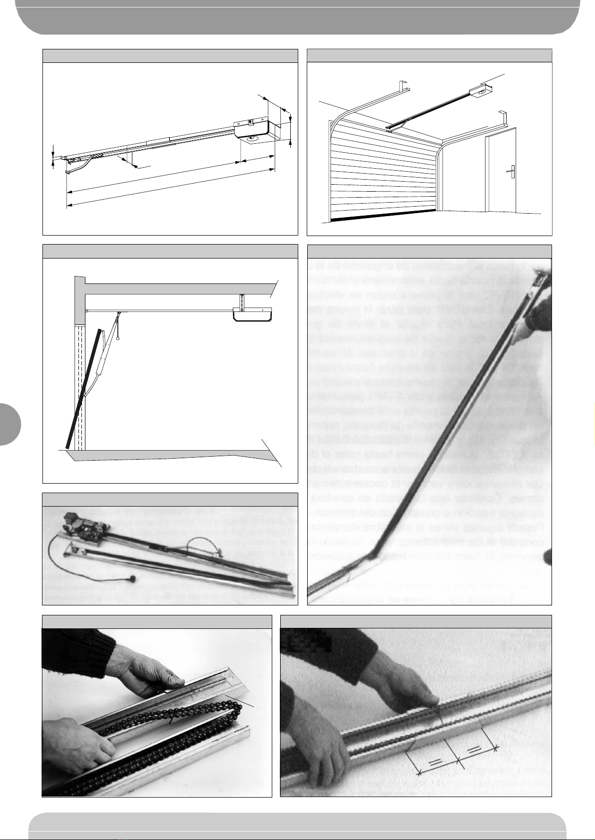
It is suitable for motorising sectional doors (fig.14), protruding fully retracting
spring-operated overhead doors (fig.2) and counterweight overhead doors
provided with an appropriate towing arm (fig.3). The overhead door must
not be higher than 2.5 metres (3.5m with extension). It is easy to install and
fast to fit and does not need the door to be modified. The irreversible
gearmotor keeps the door locked in the closing position. The control unit is
built-in. It controls the operation relays and the safety devices (photocell,
rubber skirt) before performing every manoeuvre.
3) TECHNICAL SPECIFICATIONS
3.1) Actuator
Power supply: ................................ 230V ±10%, 50-60Hz Single-phase(*)
Motor voltage: ................................................................................... 24Vdc
Max power absorbed from mains:................................................... 140W
Lubrication: ................................................................... Permanent grease
Towing and pushing force: ................................................................ 600N
Working stroke:............................ 2.55m (extended to 3.5m in Mod.PT1)
Average speed: .............................................................................. 7m/min
Impact reaction in closing:......................Ampere-stop (Stop and reverse)
Manoeuvres in 24 hours: ...................................................................... 100
Limit switches: .................................................... Electrical and adjustable
Courtesy light:........................................................... 230V 25W max, E14
Working temperature: .......................................................... -15°C / +60°C
Degree of protection: ......................................................................... IP30
Total weight: ..................................................................................... 12 kg
Noise: .......................................................................................... <70dB(A)
Dimensions: ..................................................................................See fig.1
(*) Available in all mains voltages.
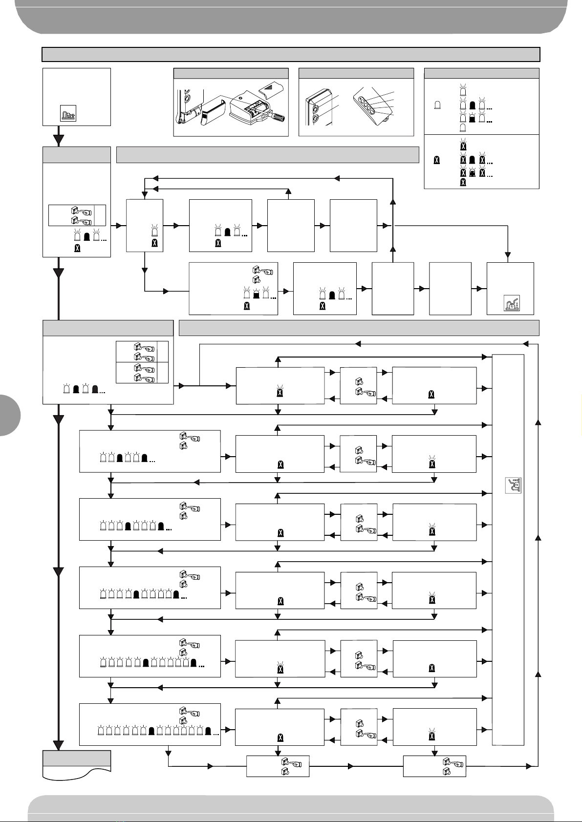
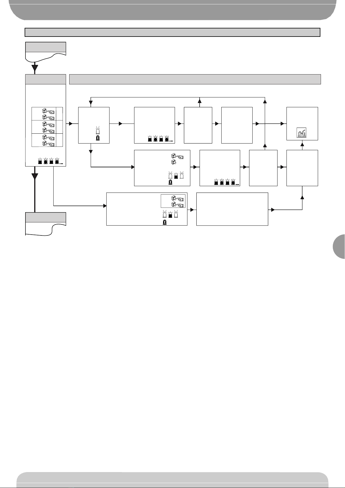
3.2) QTELEC MA control unit (fig.16)
Supply to accessories: ..................................................... 24Vac (1A max)
Ampere-stop setting: ........................................... On closing and opening
Automatic closing time: ..................................................... From 2 to 120s
Working time: ....................................................................... From 1 to 60s
Reverse pause: ........................................................................ Approx. 1s
Blinker connection: ........................................................ 230Vac max 40W
Service light switching time: ................................................................. 90s
Pre-alarm time: ....................................................................................... 3s
Parameter and option setting: ........... By means of LEDs and small keys
Incorporated Rolling-Code radio receiver: ............ Frequency 433.92MHz
Coded by means of: .............................................. Rolling-Code algorithm
No. combinations: ........................................................................ 4 milliard
Impedance antenna:.......................................................... 50Ohm (RG58)
Max no. of radio controls to be memorised: .......................................... 64
3.3) Transmitter
Key colour : .......................................................................................... Red
Power supply : ........................................................... 12V Alkaline battery
Range : ............................................................................... 50-100 metres
Transmitter versions: ..................................................................................
TRC1 - Single-channel, TRC2 - Double-channel, TRC4 - Four-channel.
4) ACTUATOR INSTALLATION
4.1) Preliminary checks
•Check that the door is balanced.
•Check that the door slides smoothly along its entire travel.
•If the door has not been newly installed, check the wear condition of all
its components.
•Repair or replace faulty or worn parts.
•The automation reliability and safety are directly influenced by the state
of the door structure.
4.2) Fitting
After being unpacked, the door opener looks as illustrated in fig.4.
Remember to dispose of all the packing elements by separating the
different types of material (cardboard, polystyrene, PVC etc.) according to
the provisions set out by the current standards.
•Remove the existing locking bolt from the cremone bolt of the door.
•Position joint “G”as shown in fig.5.
•Position the half track as in fig.6, and lower it to the supporting surface
while tensioning the chain and therefore obtaining a whole track.
•Fit the joint to overlap each of the two half tracks by half its length, as in fig.7.
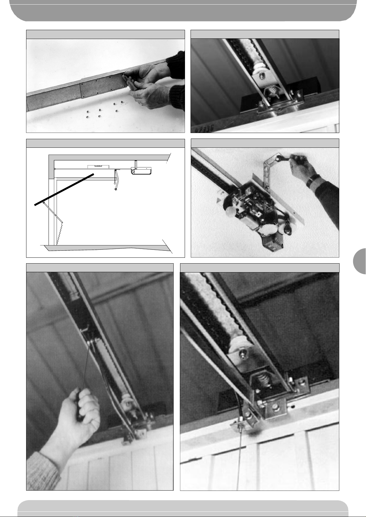
•Secure the joint by tightening the appropriate screws supplied, as in
fig.8. The door opener is thus ready to be installed.
•Mark the mid-point of the door and fix the track articulated joint to the
door frame, as in fig.9. If the ceiling is high enough, the articulated joint
can be fitted higher up and fixed to the masonry lintel by means of
dowels.
•With the help of an adequate support, lift the motorised head until the
track is levelled, as in fig.10.
•Fix the two supporting brackets to the ceiling, as in fig.11. Recheck
everything and fix the two supporting brackets to the gearmotor
base plate.
•Release the towing carriage (fig.12) by pulling the wire, and bring the
towing arm as far as the door panel. Fix the towing arm to the door panel,
as in fig.13, using the screws supplied.
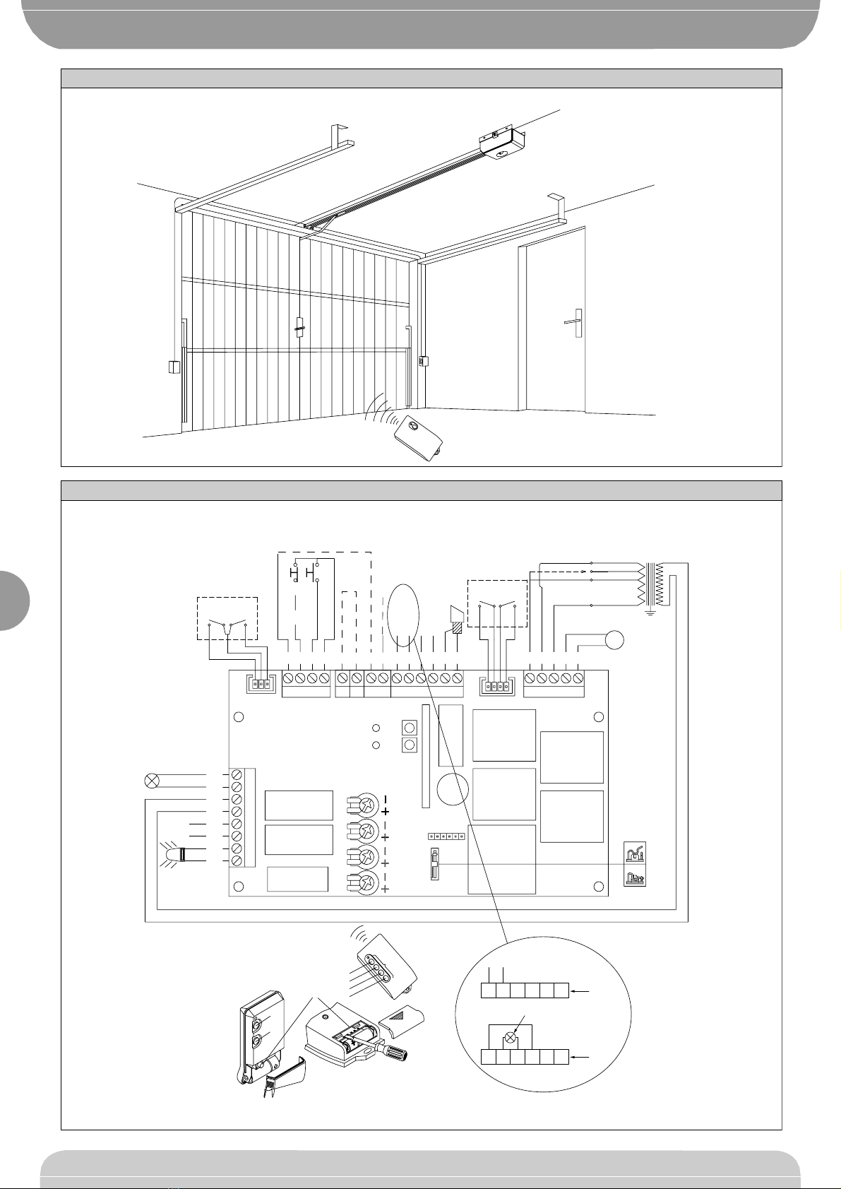
5) ELECTRICAL INSTALLATION SET-UP (fig.14)
I) Type-approved omnipolar circuit breaker with at least 3-mm contact
opening, provided with protection against overloads and short circuits,
suitable for cutting out automation from the mains. Place, if not al ready
installed, a type-approved differential switch with a 0.03A threshold just
TELEC MA
TELEC MA
AUTOMATION FOR SPRING OVERHEAD DOORS
D811266_02

288
before the automation system.
Qr) Control panel and incorporated receiver
M) Actuator
Ft) Transmitter photocell
Fr) Receiver photocells
T) 1-2-4 channel transmitter.
Connect the accessories, safety and control devices to the motor unit,
making sure that the mains voltage connections are kept totally separate
from the low voltage accessory connections. Proceed as illustrated in the
electrical diagram (fig.15). When this operation is completed, the appliance
is ready to work by means of a remote control.
5.1) Terminal board connections
The automation device is to be operated after all the safety devices have
been connected and checked. See terminal board diagram in fig.15.
JP1
1-2 Motor connection (1 Green - 2 Brown)
3 Transformer connection 0Vac
4 Transformer connection 25Vac
5 Transformer connection 15Vac
JP3A Stop microswitch connector
JP3
11-12 Antenna connection (11 signal, 12 braid)
13-14 Supply to accessories 24Vac
15-16 Free contact (N.O.) to be used as Open Gate Warning light (24Vac
max 3W) or 2nd radio channel This option can be set from menu A-
B, see paragraph on programming.
17-18 24 Vac output supplying power to the safety devices (photocell
transmitter and rubber skirt transmitter).
N.B. Output enabled during the operation cycle only.
19 Connection to FAULT safety devices (see point 6).
JP5
22-23 START button (N.O.)
22-24 STOP button (N.C.). If not used, leave bridged.
25 Electric edge photocell PHOT input (see point 6).
JP6
26-27 Courtesy light connection 230Vac max 25W
28-29 Transformer supply 230Vac
30-31 Single-phase supply 230Vac, 50/60Hz (30N-31L)
32-33 Blinker connection 230Vac max 40W
JP7
Slow-down microswitch connector.
6) CONNECTION TO SAFETY DEVICES
Note:only use safety devices whichcanreceivewith a free changeover
contact (refer to fig.12).
To connect the photocells refer to the diagram in fig.12 taking into account
the number of pairs used: 1 pair box 1C, 2 pairs box 2C.
The control unit performs the test of 2 safety devices. The additional
devices must be equipped with internal self-diagnosis and connected in
series. If photocells are not used, leave the jumpers aligned between
terminal 25/18, and between terminal 19/22 of the Q TELEC MA board.
The connection of the infrared rubber skirt must be performed in the same
way as for the photocells, i.e. by energizing the transmitter from terminal 13/
14 and the receiver from terminal 17/18.
7) MANUAL PROGRAMMING OF CONTROL UNIT
7.1) Tests
In order to facilitate the automation setup tests, to control the opening and
closing manoeuvres, you can use the remote control or temporarily connect
a button between the two terminals 22 and 23 (START).
7.2) Trimmer adjustment (fig.15)
WARNING! Before any adjustment, close jumper J1.
Set the trimmers to the requested value considering that the set value is
increased by turning the relevant trimmer clockwise.
WARNING! The values set using the trimmers must be stored in the
memory.
This operation can be carried out in 2 different ways:
a) Disconnect and then reconnect the power supply (reset) after any
correction to the trimmer. After completing the adjustment, wait at least
5 seconds from system reset and open the J1 jumper.
b) Enter “Menu A”after adjusting the trimmers (press SW1-SW2 one time
simultaneously). Check that Check that the LED flash correspond to
that of the “Menu A”(the Green LED flashes in a constant way). After
each trimmer correction, enter “Menu A”to store the new value.
TCA) Dwell time after which the door is automatically closed. Can be set
from 20 to 120 s.
AMPC) Sets the amperometric limit switch trigger current during the closing
manoeuvre (antisquash sensitivity). When the limit switch is triggered,
it stops the door and reverses the movement.
AMPO) Sets the amperometric limit switch trigger current during the
opening manoeuvre. When the limit switch is triggered, it stops the door
movement.
WARNING: Excessive value setting can jeopardise antisquash
safety. Setting must be calibrated to the minimum value needed to carry
out complete opening and closing strokes.
In any case, the pushing force at the edge of the door must be within the
limits provided for by the current standards.
TW) Sets the motor operation time, after which the motor stops. The value
set must be slightly greater than the time needed to close the door.
Can be set from 0 to 60s.
7.3) Setting of programmable parameters and functions
To program the required functions, follow the sequence described in the
“PROGRAMMING”pages. These include a “LEGEND”which explains the
types of signal indication provided by the green and red leds. For “Menu
B”, the on/off condition is specified in each individual function.
N.B. To enable function setting or modification, you must close
jumper J1 (fig.15).
Programming is divided into three menus:
A) Radio control storage
B) Function logic setting
C) Memory cancellation
To gain access to each individual programming menu, simultaneously
press keys SW1 and SW2 for a short time, as follows: once for menu A,
twice for menu B and three times for menu C.
If you do not carry out any selection within a working time of 60 seconds
after entering the programming mode, you will automatically exit
programming. When setting is completed, set J1 to Off (open the jumper).
To initialise the control unit with the required setting, disconnect the
mains power supply for a few seconds, and then reconnect it.
7.4) Transmitter storage
See the “Menu A”diagram shown on the “PROGRAMMING”page.
7.5) Function logic setting
See the “Menu B”diagram shown on the “PROGRAMMING”page.
The red led (DL1) condition (on/off) shows the function selected. The value
given within square brackets [ ] is the value predefined by the manufacturer.
Here follows a detailed explanation of “Menu B”programmable functions:
Opening photocell [ Red LED On ]
Red DL1 on: when obscured, it excludes photocell operation on opening.
Immediately reverses during the closing phase.
NB.Todisablethe opening photocell, close the J2 jumper, otherwise
the setting is not active.
Red DL1 off: when obscured, the photocells remain active during both
opening and closing. If the photocell is obscured during closing, it only
reverses the movement after the photocell has been released.
Opening impulse blocking [ Red LED Off ]
Red DL1 on: the start impulse has no effect during the opening phase.
Red DL1 off: accepts start commands during opening.
Automatic closing [ Red LED Off ]
Red DL1 on: activates automatic closing after a dwell time set by trimmer
TCA.
Red DL1 off: excludes automatic closing .
4 or 2 step logic [Red LED Off ]
Red DL1 on: 2 step logic. A start impulse given while the gate is closing,
causes the direction to reverse; during opening, it causes it to stop.
Red DL1 off: 4 step logic. A start impulse given while the gate is
moving, causes it to stop; the subsequent impulse causes the
direction to reverse.
N.B.: The start impulse during the opening phase has no effect
when the opening impulse blocking is enabled (DL1 On).
Gate-open or 2nd radio channel warning light [Red LED On]
Red DL1 on: operation as gate-open warning light (see connection fig.15).
This warning light is off when the gate is closed, blinks when it closing
and stays on when the gate is open or being opened.
Red DL1 off: operation as 2nd radio channel (see connection fig.15).
Allows other devices to be controlled through the second radio channel
of the receiver.
Pre-alarm [Red LED Off ]
Red LED on: the blinker comes on 3 seconds before the motor starts.
Red LED off: the blinker comes on at the same time as the motor starts.
7.6) Cancellation storage
See the “Menu C”diagram shown on the “PROGRAMMING”page.
D811266_02
TELEC MA
TELEC MA
AUTOMATION FOR SPRING OVERHEAD DOORS

289
8) UNIPRO UNIVERSAL PROGRAMMER (see fig.25)
The QTELEC MA control unit can be programmed by means of the
UNIPRO programmer in the following modes:
•TRC series radio control programming
•Function logic programming (No Trimmer)
•Memory cancellation
•Parameter reading
Leave the JP jumper open.
The UNIPRO connection only allows reading of those values set using the
trimmers. Connect the UNIPRO programmer to the TRC transmitter by
means of the UNITRC and UNIFLAT accessories supplied.
Connect the UNIPRO programmer to the QTELEC MA control unit by
means of
the UNIDA and UNIFLAT accessories supplied.
N.B.: The QTELEC MA control unit cannot supply the UNIPRO
programmer.
For the programming procedure, refer to the appropriate UNIPRO
instruction manual.
9) CHAIN TIGHTENER ADJUSTMENT
The automation device supplied is already calibrated and inspected.
Should the chain tension need to be adjusted, proceed as shown in fig.16.
WARNING:Theanti-tearspring must never be completely compressed.
Scrupulously check that the spring does not become totally
compressed during operation.
10) LIMIT SWITCH ADJUSTMENT
The controller is provided with a limit switch adjustment unit which is
supplied already adjusted for the maximum stroke available.
The limit switch unit has 2 microswitches for each direction: the first to be
intercepted activated slow-down operation, the second to be intercepted
stops the controller.
WARNING: Before carrying out any adjustment operation, disconnect
the power supply from the system.
Eachtime the system isdisconnectedfromthe power supply, the electronics
is reset. When the system is supplied with power, the first starting command
always activates the opening manoeuvre.
To set the opening and closing microswitches, proceed as follows:
•If the towing carriage is in the manual release position, bring it over to
the chain coupling by manually moving the door until it is hooked, and
supply the system with power.
•Press START: the first command always activated the opening
manoeuvre. Press START to stop the door when it is fully open. To set
the stroke limit, lift the retaining spring away from the cam teeth by
means of a screwdriver (fig.17), turn the opening cam in the direction of
the “OPEN”microswitches until you hear the first and second limit
switches click. Lower the spring until one of the cam teeth is engaged.
•Supply the system with power and press START to activate the closing
manoeuvre. Press START when the door is fully closed. Lift the
retaining spring away from the cam teeth by means of a screwdriver
(fig.18),turntheclosingcaminthedirectionofthe“CLOSE”microswitches
until you hear both the limit switches click. Lower the spring until one of
the cam teeth is engaged.
•Supply the system with power and check that the door slows down and
stops in both directions. Check that the opening and closing stop actions
do not require excessive towing or compression force.
•Repeat the complete opening and closing manoeuvres a few times to
check that the limit microswitches operate correctly. If necessary,
readjust the cam position.
•The retaining spring must always be engaged in the cam toothing to
keep the cams into position.
•Refit the cover on the controller.
11) SLOW-DOWN SPEED AND TORQUE
N.B.: In the case where, during the final opening and closing phases,
the pushing force does not allow the required manoeuvre to be
completed, the gearmotor force can be increased by moving the
transformer connection from terminal 3 to terminal 4, as in fig.19.
12) EMERGENCY MANOEUVRE
In case of electric power failure or system malfunction, the manoeuvre must
be carried out manually by pulling the wire connected to the carriage, as in
fig.12. For garages which are not provided with a second exit, it is
compulsory to fit an external key release device like Mod. SM1 (fig.20) or
Mod. SET/S (fig.21).
13) AUTOMATION CHECK
Before the automation device finally becomes operational, scrupulously
check the following conditions:
•Check that all the safety devices (limit microswitches, photocells,
electric edges etc.) operate correctly.
•Check that the pushing force (antisquash) of the door is within the limits
provided for by the current standards.
•Check that the chain tightener spring is not completely compressed
during manoeuvre.
•Check the manual opening control operation.
•Check the opening and closing operations using the control devices fitted.
•Check the normal and customised operation electronic logics.
14) AUTOMATION DEVICE USE
Since the automation device can be remotely controlled by means of a radio
control device or a Start button, and therefore when not in sight, all the
safety devices must be frequently checked in order to ensure their perfect
efficiency. In the event of any malfunction, request immediate assistance
from qualified personnel.
Children must be kept at a safe distance from the automation
operation area.
15) AUTOMATION CONTROL
The use of this control device allows the gate to be opened and closed
automatically. There are different types of controls (manual, radio control,
magnetic card access etc.) depending on the installation requirements and
characteristics.Forthevariouscontrolsystems,seetherelevantinstructions.
The automation device users must be instructed on control and operation.
16) MAINTENANCE
Before carrying out any maintenance operation, disconnect the system
power supply.
•Periodically check chain tensioning (twice a year).
•Occasionally clean the photocell optical elements, if installed.
•Have a qualified technician (installer) check the correct setting of the
electronic clutch.
•When any operational malfunction if found, and not resolved, disconnect
the system power supply and request the assistance of a qualified
technician (installer).
When the product is out of service, activate the manual release device
to allow the door to be opened and closed manually.
17) ACCESSORIES
SM1 External release device to be applied to the cremone bolt already fitted
to the overhead door (fig.20).
SET/S External release device with retracting handle for sectional doors
measuring max 50mm (fig.21).
PT1 1-metre extension for doors measuring up 3.50m (fig.22).
APT Extension and bracket accessories used to fit the product away from
the door or close to the ceiling (fig.23).
ST Automatic bolt release device for spring-operated overhead doors. Fitted
to the control arm, it automatically releases the side door bolts (fig.24).
18) SCRAPPING
Warning! This operation should only be carried out by qualified
personnel.
Materials must be disposed of in conformity with the current regulations.
In case of scrapping, the automation devices do not entail any particular
risks or danger. In case of materials to be recycled, these should be sorted
out by type (electrical components, copper, aluminium, plastic etc.).
19) DISMANTLING
Warning! This operation should only be carried out by qualified
personnel.Whentheautomationsystemisdisassembledtobereassembled
on another site, proceed as follows:
•Disconnectthepower supply and the entire external electrical installation.
•In the case where some of the components cannot be removed or are
damaged, they must be replaced.
The descriptions and illustrations contained in the present manual
arenotbinding.TheCompanyreservestherighttomakeanyalterations
deemed appropriate for the technical, manufacturing and commercial
improvement of the product, while leaving the essential product
features unchanged, at any time and without undertaking to update
the present publication.
D811266_02
TELEC MA
TELEC MA
AUTOMATION FOR SPRING OVERHEAD DOORS

290
Simultaneously press
control unit keys
SW1 and SW2
twice and release
Green
1 blink 1 pause
SW1
SW2
SW1
SW2
1
2
11Red
[
On
]
Green
2 blinks 1 pause
1 1
OPENING PHOTOCELLS
ACTIVE
SW2
Press
OPENING PHOTOCELLS
EXCLUDED
Red
[
Off
]
Green
3 blinks 1 pause
Press
Red
[
Off
]
Wait for 60s to exit programming or disconnect supply
OPENING IMPULSE BLOCK
EXCLUDED
Red
On
Red
[
Off
]
AUTOMATIC CLOSING
EXCLUDED
AUTOMATIC CLOSING
ACTIVE
Red
[
On
]
4 STEP LOGIC ACTIVE
2 STEP LOGIC ACTIVE
Green
4 blinks 1 pause
Press
1 1
1 1
SW1
SW1
Red
[
Off
]
Red On
SW1
GATE-OPEN WARNING
ACTIVE (no 2nd channel)
2nd CHANNEL ACTIVE
(no gate-open warning)
Green
5 blinks 1 pause
Press
1 1
Red
[
On
]
Red Off
SW1
1 1
PREALLARME ESCLUSO
PRE-ALARM ACTIVE
Green
6 blinks 1 pause
Press
Red
[
Off
]
Red On
SW1
Press SW1
Menu A
Menu B
Menu A - TRANSMITTER STORAGE
Menu B - FUNCTION LOGIC SETTINGS
Menu C
OPENING IMPULSE BLOCK
ACTIVE
Open jumper J1 at the end of programming
SW2
SW2
SW2
SW2
SW2
Press
Press
Press
Press
Press
Press
Press SW1
Check that J2 is closed.
Green
LED
Red
LED
On
Blinking
Off
Emits 1 blink
On
Blinking
Off Emits 1 blink
1
1
Red
Press P1
(see fig. 1A)
Green
Red
Press T1,T2,T3 or T4
(see fig. 2A)
Green
Red
START
2nd RADIO
CHANNEL
NOTE: Set
2nd channel
in Menu B
Press SW1
in control unit
Red
Emits 1 blink
Press T1,T2,T3 or T4
(see fig. 2A)
Green
Red
To memorise another transmitter in the
Start
Wait for 60s
to exit
programming
or disconnect
supply
To memorise another transmitter in the 2nd Radio channel
SW1
SW2
1
SW1
SW2
1
Simultaneously press
control unit keys
SW1 and SW2
once and release
OFF
P1 T1
T2
T1
T2
T3
T4
TRC 1-2 TRC 4
FIG. 1A
FIG. 2A
TRC 1-2 TRC 4
LEGEND
ON
Close jumper
J1
in the control unit
Open jumper
J1at the
end of
programming
OFF
Wait for 60s
to exit
programming
or disconnect
supply
Transmitter
key T is
memorised
as
2nd RADIO
CHANNEL
Transmitter
key T is
memorised
as
START
Green
D811266_02
TELEC MA
TELEC MA
AUTOMATION FOR SPRING OVERHEAD DOORS
PROGRAMMING

291
Press P1 on the
transmitter to be
cancelled
(see fig. 1A)
Red
Press T1,T2,T3 or T4
to be cancelled from
QTELEC memory
(see fig. 2A)
Cancellation
of START
on memorised
transmitters
Press SW1
on control unit
Press T1,T2,T3 or T4
to be cancelled from
QTELEC memory
(see fig. 2A)
To cancel another T key from the transmitter itself or another transmitter
Key T on the
transmitter,
memorised as
[START]
is cancelled
from QTELEC
memory
2nd CHANNEL
cancellation
on memorised
transmitters
Simultaneously press SW1 and
SW2 for 10 seconds on Qtelec
control unit
Red Off
Green On, emits 1 blink
All memorised transmitters are cancelled
and all QTELEC parameters modified.
Only parameters set by manufacturer
are left and specified in paragraphs
“Function logic settings”between
square brackets [ ].
Total cancellation of QTELEC
transmitter memory and
modifications
(only data set by
manufacturerleft)
Green
Alternate blinking
Green-Red
Alternate blinking
Green-Red
Red Off
1
1111
1111
1
SW1
SW2
Simultaneously press
control unit keys
SW1 and SW2
3 times and release
SW1
SW2
SW1
SW2 1
2
Menu C Menu C - QTELEC CONTROL UNIT MEMORY CANCELLATION
Alternate blinking
Green-Red
1111
SW1
SW2 3
Wait for 60s
to exit
programming
or disconnect
supply
Key T on the
transmitter,
memorised as
[2 CHANNEL]
is cancelled
from QTELEC
memory
Wait for 60s
to exit
programming
or disconnect
supply
Menu A
SW1
OFF
Open jumper
J1
at the end
of programming
Menu B
Green On emits
1 blink
D811266_02
TELEC MA
TELEC MA
AUTOMATION FOR SPRING OVERHEAD DOORS
PROGRAMMING

292
D811266_02
Fig. 1
Fig. 4
Fig. 5
207
40
132
67
370
3350
2980
Fig. 2
G
Fig. 3 Fig. 6
Fig. 7
TELEC MA
TELEC MA
AUTOMATION FOR SPRING OVERHEAD DOORS

293
D811266_02
Fig. 8 Fig. 9
Fig. 11
Fig. 13
Fig. 10
Fig. 12
TELEC MA
TELEC MA
AUTOMATION FOR SPRING OVERHEAD DOORS

294
D811266_02
Fig. 15
Fig. 14
Qr
M
T
Ft Fr
22
4x1mm
2
2
4x1mm
2x1mm
LINE 3x1.5mm
LINEA •LINE •LIGNE
LEITER •LINEA •LINHA
L
N
2425 23 22 151617181920 1113 1214
31
32
33
30
29
28
27
26
5 4 123
1
JP10
SW1
SW2
DL1
DL2
BL-STOP N.C.
START N.O.
COM
SCA - 2ϒCh.R
JP14
JP15
JP13
25-27V
20-21V
15-16V
0V
230V 25W
230V
MAX 40W
STOP-OPEN
STOP-CLOSE
RAL-OPEN
RAL-CLOSE
M=
JP1
JP3A
JP3JP5
JP7
JP6
ON
OFF
J1
AMPO
2ϒCh.R
AMPC
TCA
TW
FUSE T2A
FUSE T1.6A
QTELEC
T4
T3
T2
T1
T2
T1
P1
P1
TRC1-2-4
TRC4
16 15 14 13 12 11
2ϒCh.R
24Vac 3W
16 15 14 13 12 11
SCA
24Vac
COM
24 VAC TX
P1
FOT. PHOT. PHOT. PHOT FOT. FOT.
COM •COMMON •COMMUM •GEMEINSAM •COMÚN •COMUM
RAL-APERTO •RAL-CHIUSO
RAL-OPEN •RAL-CLOSED
RAL-OUVERT •RAL-FERME
RAL-OFFEN •RAL-GESCHLOSSEN
RAL-ABIERTO •RAL-CERRADO
RAL-ABERTO •RAL-FECHADO
STOP-APERTO •STOP-CHIUSO
STOP-OPEN •STOP-CLOSED
STOP-OUVERT •STOP-FERME
STOP-OFFEN •STOP-GESCHLOSSEN
STOP-ABIERTO •STOP-CERRADO
STOP-ABERTO •STOP-FECHADO
FUSIBILE •FUSE •FUSIBLE •SCHMELZSICHERUNG •FUSIBLE •FUSÍVEL
GUASTO •FAULT •SCHADEN •AVERIA •AVARIA
FAULT
TELEC MA
TELEC MA
AUTOMATION FOR SPRING OVERHEAD DOORS

295
D811266_02
Fig. 16
Fig. 19
Fig. 17
Fig. 18
1
2
1
2
JP1
JP1
-
---
-
----
-
---
-
2314545312
1APERTO •2CHIUSO
1OPEN •2CLOSED
1OUVERT •2FERME
1OFFEN •2GESCHLOSSEN
1ABIERTO •2CERRADO
1ABERTO •2FECHADO
1APERTO •2CHIUSO
1OPEN •2CLOSED
1OUVERT •2FERME
1OFFEN •2GESCHLOSSEN
1ABIERTO •2CERRADO
1ABERTO •2FECHADO
TELEC MA
TELEC MA
AUTOMATION FOR SPRING OVERHEAD DOORS

296
D811266_02
Fig. 21
Fig. 20
UNIDA
UNIFLAT
UNITRC
UNITRC
UNIFLAT
UNIPRO
UNIFLAT
Contatti
TRC1-2-4
QTELEC
Fig. 22
Fig. 23
Fig. 24
Fig. 25
CONTATTI
CONTACTS
CONTACTS
KONTAKTE
CONTACTOS
CONTACTOS
CONNETTORE JP10
CONNECTOR JP10
CONNECTEUR JP10
STECKVERBINDER JP10
CONECTOR JP10
CONECTOR JP10
TELEC MA
TELEC MA
AUTOMATION FOR SPRING OVERHEAD DOORS
Table of contents
Other BFT Door Opening System manuals