QUAD EZ-7000 Service manual

- 1 -
361-510-4149 Service
361-884-8006 Sales
Owner and Installation Manual For:
QUAD EZ-7000
LOW ENERGY AUTOMATIC SWING
DOOR OPERATOR
PLEASE READ THIS ENTIRE MANUAL AND FOLLOW ALL GUIDELINES TO
ENSURE PROPER INSTALLATION AND SAFETY
PROUDLY DISTRIBUTED BY…
ANSI/UL 991, 325 & CAN/CSA 27 Listed
REV. 1.29.19

- 2 -

- 3 -
READ THIS FIRST!
Quick Start Instructions
Caution: When used in a low energy installation, the EZ-7000 operator and
associated ES500 control must be installed and adjusted in accordance with
ANSI 156.19.
Warning: The ES500 control must remain connected to the operator at all times.
Never leave the operator without a control connected, as the closing speed will be
uncontrolled and may cause severe damage to the operator or door. Manual
operation must never be permitted with the control removed.
Attention: This unit has been pre-programmed to a generic 90-degree opening
position. Please follow the instructions below.
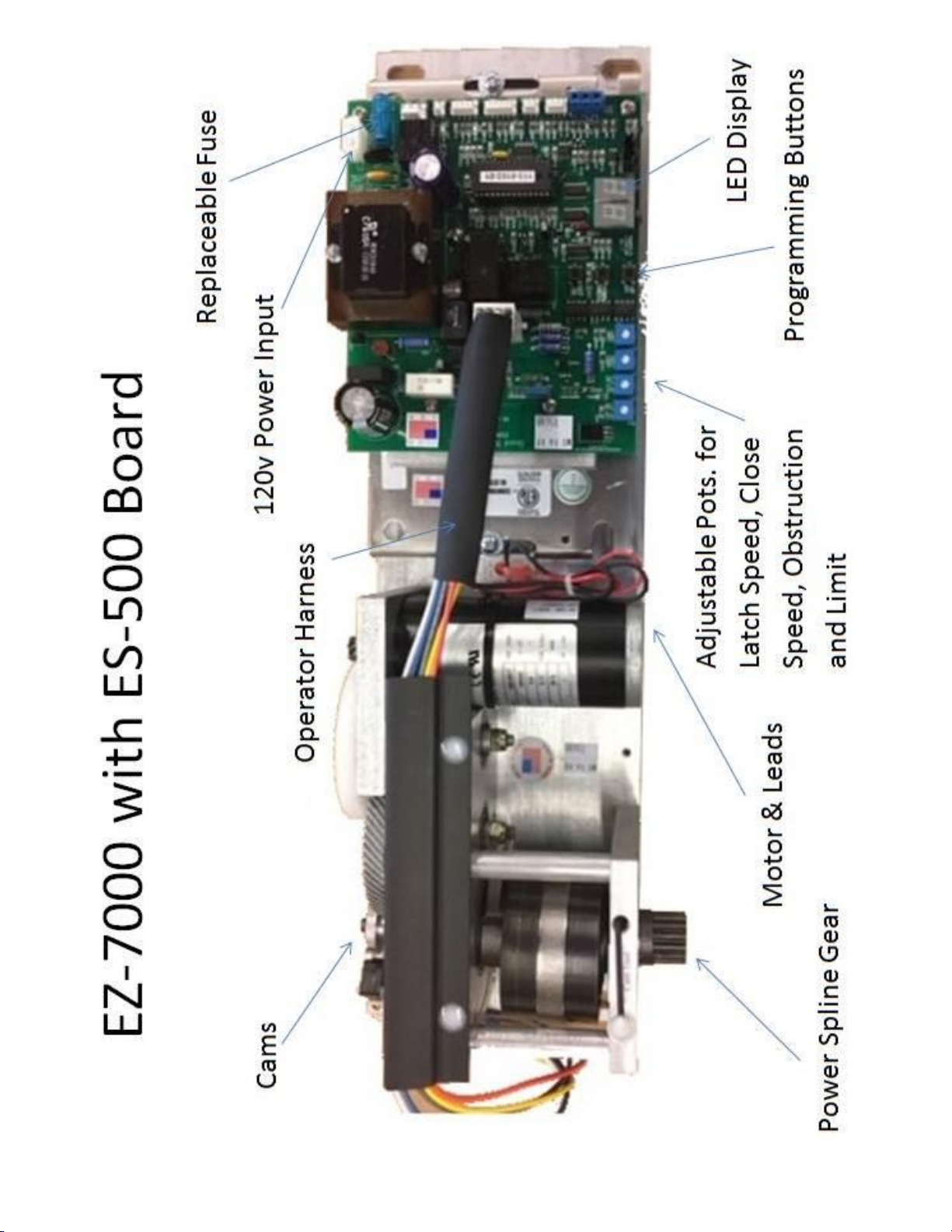
1. Plug in the wiring harness from the controller to the operator.
2. Plug in the Hold-Automatic-Off (HOA) harness ONLY. Do not plug in any
additional accessories, i.e. safety switches, door lock switches or actuating
devices.
3. Plug in motor and check for polarity. (Motor should return slowly to the stop
position when closed manually if wired correctly).
4. Plug in power supply. Turn HOA switch to the HOLD position. The motor should
open to the full hard stop position.
5. Install arm and check the outside cam. The cam switch arm should be in the
down position (flat part of cam).
6. Turn power off and let door close completely. Check inside cam. The switch
should be in the down position (flat part of cam)
7. Turn power on. After a couple of seconds, the Id light should be on. Test door
by pressing the Down button on the control board.
You are now ready to fine tune the Controller and install accessories. Please refer to
the ES500 Swing Control Installation instructions attached.
Note: Due to the method used for synchronization, it is not possible to have different
values for the standard delay (d1) and the close recycle delay (d3). Delays d1 and d3
should be set to the same value in each operator, and must also be set identically on
both operators. The push-n-go delay (d2) may be different from d1/d3, but should
also be set identically on both operators. This restriction does not apply to single
operators.

- 4 -

- 5 -
CAUTION
An improperly installed and/or adjusted Automatic Door can cause injury and
equipment damage.
Door must be installed and adjusted as described in this Owner’s Manual by a certified
professional.
All required safety devices must be in place and operational.
Door must be inspected DAILY. If the door is not functioning correctly it must be taken
out of Automatic Service immediately until a Certified Technician inspects and repairs
the unit.
DO NOT ATTEMPT TO ADJUST OR REPAIR THE DOOR YOURSELF
CALL YOUR AUTOMATIC DOOR SUPPLIER FOR REPAIRS
To our Customers
The purpose of the manual is to familiarize you with your automatic door system. It is essential that you
know your system and that you recognize the importance of maintaining your door system in compliance
with the industry standards for safety.
It is your responsibility, as owner or caretaker of the equipment, to inspect the operation of your door
system on a daily basis, and after any loss of electrical power, to ensure that it is safe for use by your
invitees, customers, or employees.
Daily Safety Checks are the responsibility of the equipment owner or caretaker. The Following safety checks
are to be done daily and/or after any electrical power outages:
1. When actuated, the door should slowly open at a smooth pace (5 seconds min.) until gently stopping
at the pre-set fully open position.
2. The door should hold open for the pre-set time of not less than 5 seconds
3. The door should then slowly close at a smooth pace (5 seconds min.) and stop gently.
4. Make sure the traffic path and threshold area are clean and clear inside and outside of doorway
5. Inspect the door, safety decals, connecting arms, hardware and glass for wear or damage.

- 6 -
NOTE: The Association of Automatic Door Manufactures (AAADM) has established a program
to certify automatic door inspectors. Though this program, the inspectors are trained to
check your door systems for compliance with the American National Institute’s standard
ADSI/BHMA A156.10
WARRANTY:
Quad Systems, LLC (seller) warrants to the Buyer all products which Quad Systems, LLC
manufactures to be free from defects in material and workmanship, under normal use and
service, for twelve months from the date product is purchased. The Seller’s obligation under
this warranty is limited to the repair or replacement at the factory, of any parts which shall
be returned to the Seller with transportation charges prepaid and which after examination,
prove to be defective. This warranty shall not apply to such products which have been
altered or repaired by other than an authorized agent. Authorization shall be in writing by
Quad Systems, LLC. Warranty does not apply if products have been subject to misuse,
negligence or accident.
There is no expressed or implied warranty by Quad Systems, LLC except as specifically stated
above.
Quad Systems, LLC shall not be liable for special or consequential damage, nor for claims of
any third party against the buyer.
NOTE: Quad Systems, LLC units are identified by serialized numbers (stamps or stickers) and
recorded by sales purchase order numbers, date sold, date made and date tested. Removal
or defacing of serial number tags will void warranty.
SERVICE AVAILABILITY:
Quad Systems, LLC products are distributed throughout the United States and Canada by a
network of authorized distributors for sales, installation and service.
IF YOUR AUTOMATIC DOOR IS NOT WORKING PROPERLY
TURN IT OFF, AND
CALL YOUR AUTOMATIC DOOR SUPPLIER.

- 7 -

- 8 -

- 9 -
Quad Systems, LLC
EZ-7000 Automatic Door Operator
Mounting Instructions
Attention: Important Installation Instructions. Read and follow all Installation
Instructions. Save these Instructions.
This device is to be installed by an experienced, trained installer in accordance with ANSI A156.19
American National Standard for Power Assist and Low Energy Power Operated Doors as well as all
local codes.
WARNING: The EZ-7000 may be used for Residential or Commercial interior doors only with widths up to
48" (1220 mm) and a maximum weight of 200 lb. (91 kg). The operator can open the door up to an opening
angle of 110° for maximum accessibility. All switching devices must be in sight of the door it operates.
120-volt electrical supply supplied by others in accordance with all local codes. This unit must be
grounded.
Do NOT connect opener to source of power until instructed to do so.
Step One-Mounting the Header
•Make sure the mounting area has proper support for the unit. Wood studs or blocking in wallboard
is recommended.
•On each side of the door frame the header should overlap by 1½” on each side. If the header does
not overlap each side by 1 ½”, the output shaft should measure 4” from center to the inside of the
hinged side of the opening.
•The bottom of the unit should be ¾” to the inside of the doorframe (see drawing below).
•Drill holes in back of header and install a minimum of 6 correct fasteners for the wall material. The
unit must be mounted level and in a secure manner.
NOTE: If door is an In-Swing, allow 8” minimum between header and opposing wall to allow
clearance for the Pull Arm.
8”

- 10 -
Step Two-Mounting Operator-Controller
•Move square nuts provided in header slots to pre-marked positions.
•Lift unit into header and secure with the 4 bolts provided making sure output shaft is at center of
opening.
WARNING: The closing speed control is built into the Controller. DO NOT wind or rotate the motor until
the Controller is installed and plugged in or serious damage could be inflicted on the Controller as well as the
installer.
•Install the Hold-Open-Automatic (HOA) switch into the end cap hole provided on each end and
plug in wiring harness from switch and operator into marked pins.
WARNING: Do NOT connect opener to source of power until instructed to do so.
NOTE: At this point do not install any other device into the controller i.e., switch harness lock
harness, safety harness, radio harness, etc…
Step Three-Mounting the Arm, Rod and Rod Swivel
•Install Rod Swivel as shown below using dimension chart below.

- 11 -
Installing Power Arm and Rod
•Prepare Power Arm and Rod as per drawings and charts.

- 12 -

- 13 -
ES-500 Swing Control Installation
WARNING: When used in a low energy installation, the EZ-7000 operator and associated ES500
control must be installed and adjusted in accordance with ANSI 156.19 documentation.
WARNING: The ES500 control must remain connected to the operator at all times. Never leave the
operator without a control connected, as the closing speed will be uncontrolled and may cause
severe damage to the operator or door. Manual operation must never be permitted with the control
removed.
1.0 Wiring –On/Off Switch and Incoming Power
If the installation consists of a synchronized pair of operators,
see the special note on page 5.
Install the supplied on/off/hold switch in the desired location and route the switch lace into the
header. Plug the connector into SWTCH input CN4 on the control.
Verify that the circuit breaker in the AC panel supplying power to the operator is off. Connect the
power cable supplied to the incoming wires (black, red or blue incoming in to black on power cable
and the white wire to the white wire). The incoming ground wire must be connected to the frame of
the operator using the ground screw provided. Restore power via the building circuit breaker, but do
not plug the line power harness into the control yet.
The actuating devices, plus any optional devices, will be wired in a later step. If a lock is present,
temporarily disable it to keep it from jamming the door while setting up the operator.
2.0 Initial Setup
WARNING: In the next step you will be applying power to the operator in order to install the
operator arm. Avoid all moving parts!
Turn the unit on and set the on/off/hold switch to the “Hold” “=” position. Physically inspect the
operator to ensure that it is against the internal open stop. Next, position the door at the full open
position and securely install the arm on the operator. The exact steps needed will vary depending
on the type of door installation (in-swing or out-swing). Refer to the operator instructions for further
details.
1.2 Adjustment Procedure
During the following sections, if any delays, options, or speeds (other than the closing speeds) need
adjustment, switch the on/off/hold switch to the off position. An indicator on the display will begin
winking, and the display will switch to the menu of adjustable parameters. Use the UP or DOWN
buttons to find the parameter you wish to change. When you have located it, press and hold the
SET button. The display will change to the current value of that parameter. While continuing to hold
the SET button, use the UP or DOWN buttons to find the new value you wish to use. When you’ve
found it, release the SET button. Switch the door back on and check the operation using the new
value(s). Refer to Section 1.7, Parameter List, for descriptions of the parameters and their factory
defaults.

- 14 -
Important: Be sure to save any changes you make before leaving the jobsite! Changes are not
stored in the ES500 control’s permanent memory until you save them. To save your
parameters, with the door in normal operation, press and hold the SET button until the display
winks dS (data Saved). Your parameters are now stored in the control’s permanent memory.
WARNING: The LIMIT, OBST, CLS SPD, and LAT SPD screwdriver adjustments are in close
proximity to electrically hot parts. Be careful to avoid contact with any parts while making
adjustments.
1.3 Closing Adjustments
After the arm is installed, turn the on/off/hold switch to the “Off” position. The door will close.
Physically inspect the latch check switch (switch with the blue, gray, and white wires) and its
associated cam. The switch arm should be on the CENTER flat side of the cam. (The arm of the
latch check switch should remain depressed from the full open position until the door is
approximately 10-15° from the full closed position, and then it must release.) Adjust the cam
as necessary. Next, adjust the CLS SPD (close speed) and LAT SPD (latch speed) pots for the
desired closing operation. DO NOT ADJUST WHEN THE DOOR IN IN MOTION. The door may be
manually opened as many times as necessary to complete these adjustments.
1.4 Opening Adjustments
Turn the on/off/hold switch to the “Hold” position and let the door fully open. Physically inspect the
open check switch (switch with orange and yellow wires) and its associated cam. The switch arm
should be on the CENTER flat side of the cam. (The arm of the open check switch should
remain depressed until the door is approximately 30° from the full open position, and then it
must release.) Do not proceed further until you have verified the adjustment of this cam.
Temporarily set both the LIMIT pot and the OBST pot fully counterclockwise. Insure that the
on/off/hold switch is in the ON position.
If the display is upside down, unplug the unit, press and hold the bottom button while plugging the
power connector back into CN9 on the control until it lights up, then release. This will flip the display.
HINT: If the door remains closed but the display does not switch to Id, insure that the latch check
cam has been adjusted properly (Section 1.3, Closing Adjustments) and that the rocker switch is in
the ON position. If the door tries to open, insure that the rocker switch is not in the HOLD position
instead of the ON position.
Cycle the door by pressing and holding the DOWN button (this button functions as an actuate signal
when the door is in normal operation, allowing easier testing). The door should cycle open. The
display will show OS (Open Speed) before the open check switch releases. It will switch to OC
(Open Check) in the open check zone. If the DOWN button is held long enough, the display will
switch to HO (Hold Open).

- 15 -
When the DOWN button is released, the door will begin closing after the d1 time delay expires.
Cycle the door several times using the DOWN button and check for proper operation. If any speeds
or delays need to be changed, follow the instructions in Section 1.2, Adjustment Procedure.
WARNING: The following two paragraphs describe the limit and obstruction sensing features of the
ES500 control. The limit feature must be set properly for low energy applications. It is also highly
recommended that the obstruction-sensing feature be used for maximum pedestrian safety. The
open speed and check speeds should be properly set before attempting to adjust the added safety
features.
The limit feature, when properly adjusted, allows faster open speed while maintaining safety by
limiting the maximum torque output of the operator. Adjust the LIMIT pot clockwise to reduce the
opening force to the desired maximum. Clockwise adjustment increases the limiting and reduces
the force available.
The obstruction sensing feature of the ES500 control, when properly adjusted, switches the door
to a much lower hold-open force if an obstruction is encountered during door opening. Adjust the
OBST pot clockwise sufficiently to obtain an obstruction response when an obstruction is
encountered. When an obstruction is sensed, the display will switch from OS to Ob (Obstruction)
and the control will switch to hold open voltage. After a brief delay, the display will switch to SS
(Seek Speed) and the door will creep the rest of the way open, after which normal operation will be
restored. Set the seek speed just high enough to ensure that the door creeps open following an
obstruction response timeout.
Note: If the LIMIT adjustment is turned up too far, it may not be possible to get the
obstruction response.
1.5 Actuating & Accessory Wiring
Remove power from the control. Wire the actuating device(s) to ACT connector CN2 as shown in
the wiring diagram. Note that total accessory device current draw should be limited to 0.5A or less.
A radio receiver may be wired directly into CN2, or for easier installation, an optional dedicated
harness may be plugged into RADIO connector CN3 and wired to the receiver.
The remaining connectors are for optional features and are normally unused in low energy
installations. If they are used, wire them as shown in the wiring diagram.
The control directly supports the use of automatic locks of either the mortise or magnetic type. An
optional lock harness must be obtained from Quad Systems. If a lock is to be used, wire it to the
lock harness as shown in the diagram. Typically, the normally closed relay contact is used with
magnetic locks and the normally open contact for mortise strikes. Be sure to adjust lock parameters
LL and UL as shown in Section 1.7, Parameter List, before attempting operation with a lock.
Do not attempt to power the lock from the control unless the total accessory current draw,
including lock, is 0.5A or less.
After all other devices are wired, power the control back up and check for proper operation. The
green ACT(ACTuate) indicator should light whenever an external actuating device (including the
radio receiver) triggers the door to open. The Red SAF (SAFety) or yellow SNS (Stop-N-Seek)
indicators should light if any of the optional safety devices are active. If any auxiliary switches or
devices are used (see the AF parameter description below), the yellow AUX (AUXiliary) indicator
should light whenever they are triggered.

- 16 -
1.6 Display Codes
During normal operation, the ES500 control displays its current status via the display as follows:
Id Idle, awaiting open command
SA SAfety device active, door prohibited from opening
OS Opening door at Open Speed
OC Opening door at Open Check speed
HO Holding Open
OP Manual Opening detected (with PG turned off)
CL CLosing door, with speed set by close speed adjustment
LC Closing door at Latch Check speed, latch check delay running
SS Opening door at Seek Speed (following obstruction)
Ob Obstruction detected, door stalled**
d1 Time delay 1 in use (delay for hold open time) *
d2 Time delay 2 in use (delay for push and go actuation) *
d3 Time delay 3 in use (delay for touch-stop recycle) *
The normal display sequence during a cycle is OS –d1 (or d2) –OC –HO, then CL –LC –Id.
1.7 Parameter List
The following list shows all adjustable parameters in the ES500 control, along with a brief
description of their function and their factory default values.
OS Open Speed. Sets the opening speed of the door before the open check switch is released.
Possible values are 0-15, and default is 4.
OC Open Check. Adjusts from 0-15. Default is 9. Determines opening speed after the open check
switch is released (within the last 15-45° of door opening).
HO Hold Open. Adjusts from 0-15. Default is 3. Should be adjusted to the minimum POWER (not
time) required to keep the door from drifting closed after the display switches to HO.
SS Seek Speed. Adjusts from 0-15. Default is 5. Should be adjusted to make the door creep open
following the "obstruction" response (see Section 1.4).
AC ACceleration. Determines how fast the door ramps up to open speed following an actuate
command. Possible values are 0-15, and the setup default is 15 (maximum acceleration).
dC decceleration. Determines how fast door slows down after the open check switch is released.
Possible values are 0-15. The setup default of 0 switches door immediately from "speed" to "check"
with no ramp-down.
UJ UnJam power. Determines amount of power the control applies in the closing direction to unjam
the lock and/or door prior to opening. Possible values are 0-16, and the setup default is 0 (do not
apply unjam power). Note that unjam power may be used with or without a lock present.
d2 Time delay 2 (push and go). This delay is used only when the door has been actuated by a push
and go signal. The time delay begins when the door reduces speed to open check. Possible values
are 1-99 seconds and the setup default is 1 second.
Note: d1 takes priority over d2. If the door is opened via push and go, then a standard actuating
signal (pushbutton etc.) is received, d1 replaces d2.
d3 Time delay 3 (close recycle). This delay is used only when the door has been recycled by an
obstruction detected while attempting to close. The time delay begins when the door reduces speed
to open check. Possible values are 1-99 seconds, and the setup default is 1 second.

- 17 -
For paired operation, d3 must be set the same as d1 (see notes on page 10).
LC Latch Check delay. This delay begins when the door reduces speed to latch check. It should be
set to ensure that the door is fully closed before the display switches from LC to Id. It prevents the
safety devices, if any, from being re-enabled too early during the closing sequence. The safety
devices are automatically "locked out" while the door is closing (display shows CL) and while the
latch check delay is running as well (display shows LC). Possible values are 1-99 seconds; default
is 3 seconds.
UL UnLock delay. This delay should be set to ensure that the lock retracts before the door begins
opening. It is displayed in 0.1second intervals, and possible intervals are 0.1-9.9 seconds. The
default of 0.8 seconds is sufficient for most magnetic locks.
AF Auxiliary Function. This parameter defines the function of auxiliary input connector CN7. The
default value of 1 enables CN7 to be used as a close monitor switch input. Setting AF to 2 allows
this connection to be used for approach side sensors that function only as recycle/hold open
devices (the devices are ignored when the door is closed). Setting AF to 3 allows this connection to
be used for a safety beam input. Other values of AF are reserved and disable the CN7 input when
selected.
ct Cycle Test. This cycles the door at regular intervals for testing. Default is off.
PG Push And Go. This automatically completes a cycle if someone begins pushing the door open
manually. Default is off (no push and go). Also see the d2 parameter.
Cr Close recycle. This recycles the door open if an obstruction is encountered, during closing, prior
to the door entering latch check. Default is on.
SL SLower open speeds. This reduces all open speed settings by approximately 50%, allowing the
use of very slow open speeds if desired. Remaining speeds (open check, hold open, etc.) are not
affected by SL. Default is off (use normal open speeds).
LL Lock present. When the LL parameter is on, the control will trigger the lock relay prior to
opening. It will also attempt to unjam the door, if requested (see the UJ and UP parameters), and
will wait through the unlock delay (see the UL parameter) before opening the door. Default is off (no
lock).
HS Hold Strike. If the HS parameter is left off, the lock will be released approximately 1 second after
the door begins opening. This is normally the preferred setting, as it prevents burn out or buzzing of
inexpensive mortise type strikes. If HS is turned on, the lock will be held in the released condition for
the total duration of the open cycle, the close cycle, and the latch check delay (see the LC
parameter). Default is off (do not hold strike through open cycle).
U1-3 User Parameters 1-3. These parameters adjust from 0-99 and are not used in any way by the
control itself. They may be set to any data the installer wishes to save (month/year of installation,
date of last service, technician code, etc.).
SPECIAL NOTES ON SYNCHRONIZED PAIRS
A six-conductor synchronization harness is supplied with paired operators. It is strongly suggested
that this harness be left unplugged until each door of the pair is set up properly and operating
normally as an independent unit. The harness may then be plugged into SYNC connector CN5 on
each control to synchronize the two doors.
Connections for actuating and safety devices as well as the on/off/hold switch may be made to
either control. It is not necessary to connect them to both.
Due to the method used for synchronization, it is not possible to have different values for the
standard delay (d1) and the close recycle delay (d3). Delays d1 and d3 should be set to the same

- 18 -
value in each operator, and must also be set identically on both operators. The push-n-go delay
(d2) may be different from d1/d3, but should also be set identically on both operators. This
restriction does not apply to single operators.
EZ-7000 Power Consumption
The measured currents and power consumptions for the EZ-7000 operator are as follows:
-Idle, door closed: 0.066 amperes, 8 watts
-Opening, operator only (no door attached), peak measurement: 0.46 amperes, 56 watts
-Holding open: 0.265 amperes, 32 watts
The opening power will be somewhat higher with a door attached to the operator. A conservative
estimate would be a factor of roughly two times the given figure (0.82 amperes or 112 watts) for
any reasonable door weight (up to 100-125 pounds).
The control has a 3.15 ampere fuse, so in no case will the prolonged current draw be more than
this figure, as the fuse would blow.
Another question which seems to be asked frequently regards cost of operation. It is estimated that
the cost of operation is well below $0.01 per door cycle.
It was also determined that if the door is held open all day long, 24 hours a day, the total cost per
month is $2.84.
The dollar figures given are based on energy cost of $0.12 per kilowatt hour.

- 19 -

- 20 -
Table of contents
Other QUAD Door Opening System manuals
Popular Door Opening System manuals by other brands

Assa Abloy
Assa Abloy Norton PR1601BF installation instructions

ENTRO
ENTRO D0701 installation instructions

PDQ
PDQ 3100 Instruction

Assa Abloy
Assa Abloy SARGENT 281 Series installation instructions

Hettich
Hettich InLine P Mounting-instructions and technical data

Cal-Royal
Cal-Royal CR801 Series installation instructions