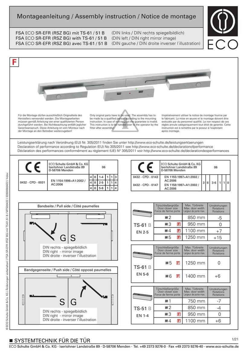
Micom 2ES ALE User manual

68MB000009
instruction
manual
revision
GENERAL
This appendix contains changes that have been made since the printing of your Owner’s Guide number
68P02952C60-A. Use this information to update your Owner’s Guide.
REVISION DETAILS
The new model numbers are M80AMN0KV5BK, M81AMN0KV5BK and M85AMN0KV5BK.
Please add the attached chapters to the above Owner’s Guide.

DATE: 10.12.01
68MB000009
PAGE 1 OF 4 PAGES
MODIFICATIONS ON MICOM-2ES
IN CONTRAST WITH MICOM-2E
CONTENTS
MICOM-2ES ALE Front Mount Model Complements & Accessories………………………………….2
MICOM-2ETS ALE Trunk Mount Model Complements & Accessories…………………………….…2
MICOM-2RS ALE Rugged Model Complements & Accessories……………...…………………….....2
TABLE: New Pin (from 26 to 44) Assignments of Accessory Connector J5……….…………………..3
RETROFIT INSTRUCTIONS FROM MICOM2 TO MICOM2S………………………………………3
MULTI – NET…………………………………………………………………………………………...3
DESCRIPTION………………………………………………………………………………...3
OPERATION OF THE MULTI-NET APPLICATION…………………..……………………4

DATE: 10.12.01
68MB000009
PAGE 2 OF 4 PAGES
MICOM-2ES ALE MODEL COMPLEMENTS
Front Mount –MODEL M80AMN0KV5BK
FLN2768A Low RF Assembly
FHN5781A Low RF Hardware
FLN9339A Lord For Micom3
FIXED ADAPTOR ACCESSORY
09MB000011 Interface connector from 25 to 44 (Note 1)
MICOM-2ETS ALE MODEL COMPLEMENTS
Trunk Mount –MODEL M81AMN0KV5BK
FLN2768A Low RF Assembly
FHN5781A Low RF Hardware
FLN9339A Lord For Micom3
FIXED ADAPTOR ACCESSORY
09MB000011 Interface connector from 25 to 44 (Note 1)
MICOM-2RS ALE MODEL COMPLEMENTS
Rugged Mount –MODEL M85AMN0KV5BK
FLN2769A Lord Unit RUG
FHN5962A Low RF Hardware RUG
FLN9339A Lord For Micom3
FIXED ADAPTOR ACCESSORY
09MB000011 Interface connector from 25 to 44 (Note 1)
Note 1: The MICOM-2ES ALE, MICOM-2ETS ALE, MICOM-2RS ALE accessory connector is 44
pin. For connecting MICOM-2E ALE, MICOM-2ET ALE, MICOM-2R ALE accessory
devices is required to connect first the fixed adapter 09MB000011. The fixed adapter is pin to
pin compatible.

DATE: 10.12.01
68MB000009
PAGE 3 OF 4 PAGES
Table: New Pin (from 26 to 44) Assignments of Accessory Connector J5
P
in
N
u
m
b
e
r
Pin Name Function
I
n
p
u
t
/
O
u
t
p
u
t
N
ot
es
26 GND Ground Output
27 GND Ground Output
28 ALE_CHANNEL_CHANGE Interrupt Change channel. Input
29 TXD_ Point to Point protocol to HOST. Input Option
30 SPARE_1 I/O Option I/O Not connected
31 AUDIO_SW Digital switch open Tx Rx audio
channel. Input
32 TX_AUDIO_OUT Audio Input to audio Tx from accessory
device. Input
33 RXD_ Point to point protocol to HOST Input
34 RX_AUDIO_OUT Audio Input to Rx audio from accessory
device. Input
35 RX_AUDIO_IN Audio Output from Rx audio to
accessory device. Output
36 ALC_500W Maintain cons. Power at 500W
transceiver output. Input
37 OPT_OUT Digital Output. Output
38 OPT_IN_OUT Digital I/O. Input/
Output
39 SPARE_2 I/O Option I/O Not connected
40 TX_AUDIO_IN Audio Output from Rx audio to
accessory device. Output
41 EXT_RX_AUDIO(2)+ HYBRID Option Output Not connected
42 EXT_TX_AUDIO(2)+ HYBRID Option Output Not connected
43 EXT_TX_AUDIO(2)- HYBRID Option Output Not connected
44 EXT_RX_AUDIO(2)- HYBRID Option Output Not connected
RETROFIT INSTRUCTIONS FROM MICOM2 TO MICOM2S:
1. Switch the LORD BOARD from FRN5869A to FLN9339A.
2. Place 150Ω-(0611077A54) resistor, parallel to R274 on the HIGH POWER BOARD.
3. Use FIXED ADAPTOR ACCESSORY- (09MB000011) to Interface connector from 25 to 44 ( If
necessary).
4. Calibrate the Power output parameters of the Radio via the Radio RSS INTERFACE, into
TECHNICIAN MODE.

DATE: 10.12.01
68MB000009
Multi-Net:
Description:
Multiple net operations:
The radio is capable of operation in multiple nets simultaneously. A net is defined as a group of
stations that scan the same frequencies. The MICOM can support, at least 20 nets. Each net includes
the following elements:
A group of receiveing and associated transmiting frequencies.
The self-address and net address that will be used when responding to calls.
The radio responds according to the selected net self-address, the total of all self-addresses are 20.
The sounding is per net (group of channels) for all channels one by one .
The starting time is 10 minute after the power is switched on. And the sounding group interval is
according to the sounding auto time that was programmed by the ALE-RSS.
PAGE 4 OF 4 PAGES
In actual operation, the MICOM radio will be scanning all the frequencies that make up the nets.
When it receives a call, it will respond with the self-address that is programmed in the radio for that
net. When initiating a call, the MICOM looks up the frequencies that are associated with the station
you are calling and uses only those frequencies to call that station. LQA exchanges or sounds will use
only those frequencies associated with the net that is selected.
Operation the Multi-Net application:
Programming and Operation:
1.Program each net according to the RSS ALE (Channels, Members and etc..)
2.After programming the ALE through the RSS the radio default scanning mode is according to the
selected NET.
3.Operating in Multi-Net:
From the control panel enter to the ALE programming menu and under the OPT tree find the Mnt
function and active this mode.
4.Calling sign length:
The default length of the calling sign is according to the channel numbers associate in the net or in all
nets in Multi-Net operation.
Under the same OPT tree we add the MxCh mode to change the calling sign length.
The MxCh numbers the channels multiply to the constant scanning time.
5. Sounding intervals:
The sounding intervals are per net.
From the control panel enter to ALE programming enter to NET programming and enter to SOND.
Define the sounding interval per net, or use the ALE RSS to define the sounding time interval.

DATE: 10.12.01
68MB000009
6. Calling in Multi-Net:
Press CALL, select the NET # , Press ENTER, select the address and press SEND.
7. Calling from single NET radio to a Multi-Net radio:
In those cases the on single NET radio you should defined the ALE signaling length according to the
channels associate in the Multi-Net radio.
Use the MxCh parameter and define the number of channels associate in the Multi-Net radio.
When selecting AUTO the radio is calculating the ALE calling sign according to the channels associate
on your radio in single NET or in Multi-Net.
This manual suits for next models
2
Table of contents
Other Micom Door Opening System manuals
Popular Door Opening System manuals by other brands
FAAC
FAAC A951 manual

Erreka
Erreka VIVO-D103 Quick installation and programming guide

Langer & Laumann
Langer & Laumann TSG Sinus Drive Installation instruction

Rubek Automatic Doors
Rubek Automatic Doors Structural Operator's manual

B&S
B&S Smart Pro SDO-9V3 installation instructions

Power Access
Power Access 2300JL installation guide
