manuals.online logo
Brands
  1. Home
  2. •
  3. Brands
  4. •
  5. Toshiba
  6. •
  7. Cassette Player
  8. •
  9. Toshiba KT-R2 User manual

Toshiba KT-R2 User manual

i6bA
STEREO
CASSETTE
RECORDER
KT—R2
CONTENTS
1:
(OPERATING
CONTROUS
:
cuss
waded
eves
Vee
ee
alu
ceeeoaseee
Ses
3
2.
DISASSEMBLY
INSTRUCTIONS
............
0.0000.
e
eee
eee
eee
4
to
5
3;
BLOCK
DIAGRAM
«60.3
o5-4.4
thveuh
weeds
be
chee
Hie
be
bee
esdlea
eos
6
4..
ALIGNMENT
INSTRUCTIONS
<.c5eesseeee0e
neh
seaesemeene
eS
7
to
8
5.
ELECTRICAL
PARTS
LOCATION
...............
000
cece
eee
eeee
9,
11
5-1
CASSETTE
RECORDER
SECTION
.............
000
cece
eee
eeeeee
9
5-2.
FM
TUNER
PACK
SECTION
...........
0.0
ccc
ee
eee
eee
een
enes
11
6.
SCHEMATIC
DIAGRAM
............
0.00
cece
eee
ee
eens
salah
tn
Set
10,
12
6-1
CASSETTE
RECORDER
SECTION
..............00
0c
cece
eee
eee
10
6-2.
FM
TUNER
PACK
SECTION
............
0.0.00
eee
eee
eee
naee
12
7.
MECHANISM
EXPLODED
VIEW
.........
0.0...
ccc
eee
eee
ean
13
8:
MOTOR
REPEACEMEN
TD
vs
s.0
du
ceu
cy
iyk
boa
Res,
paddies
kat
Shawaces
14
9.
CABINET
EXPLODED
VIEW
..............
0...
cee
eee
eee
eens
15,
18
9-1
CASSETTE
RECORDER
SECTION
.............00cc
cee
ee
ceuuaes
15
92.
EM)
TUNER:
PACK
SECTION
e055
25
Sach
duis.e
Sow
dane
ares
OBA
ae
19
10;.
PARTS
EIS
E
soto
bach
n
ee
scot
is.g
Wee
canes
Gn
ee
ae
a
16, 17,
18,
20,
23
10-1
MECHANISM
&
CASSETTE
RECORDER
CABINET...............-.
16
10:2.
“CASSETTE
ARECORDER
«a
bitch.
dy
aru
dd
hero
eke
bee
ee
ae
17,
18
10:3:
FM
TUNER
PACK:
tbc
ott
xi
eee
been
dvacada
tied
capteat
20
10-4;
SACCESORVES:
sinus
aceent
also
uteu
Goans
Dore
BA
ew
we
tds
Wie
bee
e
eeewe
23
11;
“HEADPHONE
“SECTION
(ic,
ooh.
et
sod
tbrsnerarera
dene
ating
«aun
eg
Pe
es
SRY
21,
22
11-1
HEADPHONE
EXPLODED
VIEW
(TA,
TC,
AY)...........
0.000000
21
11-2.
HEADPHONE
PARTS
LIST
(TA,
TC,
AY)...........
000 cee
eee
eees
21
11-3.
HEADPHONE
EXPLODED
VIEW
(YY,
EY,
RY,
MY).....
afi
cease
ne
22
11-4
HEADPHONE
PARTS
LIST
(YY,
EY,
RY,
MY)........000c00eeeeeee
22
Name
Label
(RP-S2)
Nameplate
(KT-R2)
TOSHIBA
amg
STEREO
CASSETTE
RECORDER
MM
MODEL
NO.
KT-R2
POWER
SOURCE
~
pc
6vV
|}
*?
SUM-3
(AA
SIZE
CELL)x4
TOSHIBA
CORPORATION
MADE
IN
JAPAN
632
Name
Label
(RP-S2)
(AY,
YY,
EY,
MY)
TOSHIBA
Toshiba
FM
STEREO
TUNER
PACK
TY,
Fas]
Oo]
od
ON)
USE
IN
COMBINATION
WITH
TOSHIBA
STEREO
CASSETTE
PLAYER
KT-S2
TOSHIBA
CORPORATION
MADE
IN
GAPAN
(TA,
TC)
TOSHIBA
FM
STEREO
Secs
eli
ed
MODEL
NO.
RP-S2
USE
IN
COMBINATION
WITH
TOSHIBA
STEREO
CASSETTE
PLAYER
KT-S2
TOSHIBA
CORPORATION
1
On|
eM
-WOb
4=>.¢-V
iV
lalon
|
TOSHIBA
MADE
IN
JAPAN
ROLS
[<4
PLAY/|RADIO]
ON]
button
[m
4
STOP/EJECT,
[RADIO]
OFF]
button
FUNCTION/PAUSE]
switch
|
:
[@
|REC!]
record
button
Pee
FF/MQTS]
fast-forward/MOTS
button
paver
el
be
REW/MOTS]
rewind/MOTS
[RADIO]
/TAPE)
button
[
(
[RADIO]
indicator
lamp
[
[D
|
|
[REC/BATT]
indicator
beirut
iMOTS
S|
SK/EDITOR]
button
-
IN
6V]
jack:
[PEAY/BATT]
indicator
Tomy
#0
nd
————-One-point
stereo
microphone
[MIC/AUX]
microphone/auxiliary
input
jack
r—[PHONES]
jack
EXT.
SPEAKER]
jack
Figute:
t.
[a
INPUT)
input
selector
|
|
Ae]
selector
:
poe
NE)
switch
(HIGH/
LOW)
Eee
nase,
er
counter
and
reset
button
Tuning
dial
pointer
[TUNING]
knob
acct
Yas
————
[STEREO/MONO]
switch
When
a
received
FM
stereo
program
is
disturbed
by
ex-
cessive
noise,
set
this
switch
to
MONO.
Otherwise,
usually
set
this
switch
to
STEREO.
OCK]
tab
tacit
ca
Figure
2.
ISASSEMBLY
INSTRUCTIONS
CABINET
BACK
REMOVAL
PAN
Screw
PAN
Screw
ip
ha
hadt
1.4¢
x
4mm
1.76
x
11mm
On
ee
Chromium-plated
Chromium-plated
)
2.
Loosen
each
set
screw
(A)
and(B)
on
the
reverse
side
9
®
of
the
back
cabinet,
two
set
screws(C)on
the
bottom
side
and
two
set
screws(D)on
the
flank
side
for
union
with
the
front
cabinet.
The
back
cabinet
will
be
ready
for
removing.
Battery
Cover
Figure
3.
Figure
4,
BID
Screw
2¢
x
8mm
©)
Chromium-plated
PAN
Screw
oN
f
1.49
x
3mm
Y
Chromium-plated
Figure
5.
=
®
BID
Tapping
Screw
€
BID
Tapping
Screw,
RED
FRONT
PANEL
REMOVAL
2%
x
6mm
\%
2.68
x
8mm
1.
Remove
the
back
cabinet.
2.
Loosen
and
remove
one
mechanical
set
screw
(E).
3.
Loosen
and
remove
one
set
screw
(F)
for
assemblying
G
the
microphone
and
(DC
in
6V)
jack
©.
The
front
(DIC
in
6V)
cabinet
is
now
ready
for
removing.
sack
FLT
Tapping
Screw
BLK
|
Figure
6.
HOW
TO
OPEN
P.C.
BOARD
1.4¢
x3.5mm
(1)
1.
Remove
the
back
cabinet.
~
aap
2.
Remove
the
PC
plate
and
one
set
screw(H)
for
the
mechanical
body.
3.
Open
the
cassette
cover
and
remove
the
base
for
the
*
t
#
fGN
rr
mechanical
body
and
the
set
screw
(1)
for
the
connector,
Figure
7.
REPAIRING
FM
TUNER
PACK
1.
Remove
six
special
screws
Gh)
on
the
bottom
side
of
3.
Open.
the
cassette
cover
of
the
recorder
and
insert
the
tuner
pack.
into
the
body
with
the
cabinet
top
removed.
This
2.
Remove
the
cabinet
top
of
the
tuner
pack.
particular
condition
permits
also
the
inspection
of
the
pattern
side
of
the
tuner
pack
PC
plate.
J)
Special
Tapping
Screw
Figure
8.
BRE
NERD
oa
IMS
ES
SEER?
CASSEITE
SLOABOE
a
at
KT—R2
3.
BLOCK
DIAGRAM
YOLdVGV
OV
|
WOVd
=
YANAL
£oor
YOLIINNOD
|
INOHdOV3H
soor
2/I
2
3NOHdGV
3H
900f
2/1
2
SNOHd
OV
3H
goof
2/|
I
SNOHdOV
3H
coor
est
pctems
bXZWEWNS
€0S
‘2060
#SzzSz¥1L
2/1
L0v0
WYvily
SLOW
Ob
‘Cod
|
!
|
NOI193130
Vel
JOVLIOA
|
AV1d/9348
|
|
|
|
AS9'0
YOLVIIONI
ONIUNG
LNVLSNOD
39N343434
206
‘106
‘vosSd
3Alua
YOLOW
dOLS
ONIUNC
90S
‘soso
INVLSNOD
©
wad
parrert
SD
en
eters
ae
a
a
DIN
NI
LTING
|
|
sezcau
2!
|
'
\
)
dWV
03
|
404
D1Ddwo>
SIOW
oe
ecclee
tse:
——
Se
9
ee
a
hte
a
tee
D
Sena
|
1
|
aye
NI
3NI1
JIW
LX3
|
LINDEID
eos
voor
2/i
a
popeenepesfpoe
Move
dS
1x3
90+0
102S
200
dWV
IW
03
334
193138
AW1d
/334
dBGOLVL
2/1
dWV
03/934
dWV
4344N8
49379S
AW1d/33a
KP
YoY
LP
ee
|
ER
av
aH
AW]d
#934
v0!
YO1D3NNOD
MOWd
YINAL
ONILOAW
401103
/
av3H
jong,
|
|
aonvawe
meee
a
CC
ova
8060
‘10b7
193738
FS
4?
1
Seas
S
aes
SS
oes
d@S9V1L
2/1
reer
a
<a
Sag
eae
19373S
dWV
03/934
£0!
a
AW1d
34
Liv
.
yo
NIo3NIT
JIW
1X3
LINDT
NOIL9310ud
IWNINA
193735
voor
2/I
dVElELVL
COLO
16€u
10¢S
GOvd
&
yo7
JIN
NILTING
Figure
12.
|
KT—R2
KT—R2
:
Generator
Couping
Hook-Up
4.
ALIGNMENT
INSTRUCTIONS
S
Curve
Supply
Figure
16.
Figure
17.
FM-RE
ALIGNMENT
BIgune)
9;
Turn
on
the
signal
generator
and
the
VTVM,and
allow
a
fifteen-minute
warm-up
period.
_
Connect
the
signal
generator
output
through
a
75
ohm
dummy
antenna
across
FM
ANT.
Connect
the
VTVM
across
a
15K
ohm
dummy
load.
Adjust
the
signal
generator
frequency
as
indicated
in
FM-RF
ALIGNMENT
CHART,
and
maintain
a
sufficient
]
.
Q201
signal
output
level
to
provide
a
measurable
indication.
E
SIO
R204
5.
Proceed
as
outlined
in
the
FM-RF
ALIGNMENT
CHART.
FM-RF
ALIGNMENT
CHART
step
|
Signal
Generator
Radio
Dial
Setting
Remarks
Figure
13.
|
87.5
MHz
Tuning
Knob
fully
OCS.
Coil
Adjust
for
maximum
LOO2
Output
indication
BwWN
=
Counterclockwise
(Lowest
Frequency)
EM-IF
ALIGNMENT
|
2
108
MHz
Tuning
Knob
fully
OSC.
Trim
Adjust
for
maximum
, ;
Clockwise
Sere
1.
Turn
on
both
sweep
generator
and
oscilloscope,
and
allow
a
fifteen-minute
warm-up
period.
(Highest
Frequency)
C004
output
indication
2.
Connect
the
RF
SWEEP
SIGNAL
OUTPUT
from
the
signal
generator
through
the
loop
antenna
to
the
receiver.
3
Repeat
steps
1
and
2
as
required.
RF
Coil
L001
Adjust
for
maximum
Tune
to
signal
Ant.
Trim.
Output
indication
C003
5.
Proceed
as
outlined
in
the
FM-IF
ALIGNMENT
CHART.
106
MHz
FM-IF
ALIGNMENT
CHART
3.
Connect
the
oscilloscope
vertical
input
directly
to
the
test
point
L
or
R=
and
connect
the
shielded
lead
to
the
9OMH
2
4.
Connect
the
SWEEP
VOLTAGE
OUTPUT
of
the
sweep
generator
to
the
oscilloscope.
5
Ee
Repeat
steps
4
and
5
as
required.
CAUTION:
When
realigning
the
FM
Receiving
Frequency,
the
highest
end
of
the
frequency
range
should
not
ae
be
more
than
108
MHz
and
the
lowest
end
of
the
frequency
range
should
not
be
less
than
87.5
MHz,
Connect
sweep
Sweep
Tuning
Knob
|
Set
scope
for
con-
Turn
the
coil
T102
fully
in
order
to
comply
with
FTZ
regulations
in
West
Germany.
generator
Output
to
generator
of
|
fully
counter-|
necting
output
counterclockwise
to
obtain
poco
ocer
oe
a
three-turn
loop
10.7
MHz
clockwise
signal
from
TUN
a
single
peak.
Fig.
16
antenna
of
10cm
center
freq.
|
(Highest
OUT
to
vertical
Adjust
coil
T1101
in
order
To
signal
generator
diameter.
with
10.7
Frequency.)
|
axis
of
scope
‘’V”
until
the
best
single
peak
(SG
imp.
50
ohm)
To
receiver
MHz
marker.
and
sweep
gener-
is
obtained.
ator
output
to
Finally
turn
the
coil
T102
i
:
E
horizontal
axis
to
obtain
S
curve.
Fig.
17
7
pee
75
ohm
dummy
antenna
FREE
RUN
FREQUENCY
ALIGNMENT
nécord
Play
wacke
Head
a
IF
Sweep
Test
Adjust
R204
under
no
signal
condition
so
as
to
obtain
76
kHz
+
150
Hz.
\
Receiver
under
test
FM
Sweep
Generator
SWEEP
VOLTAGE
OUTPUT
RECORD/PLAYBACK
HEAD
ADJUSTMENT
A
6.3
kHz
standard
tape
must
be
used
for
this
adjustment.
Connect
a
VTVM
or
an
oscilloscope
to
the
EXT
Speaker
jack
and
adjust
the
azimuth
by
using
a
phillips
screwdriver
to
maintain
the
maximum
output
voltage.
Figure
18.
Record/Playback
Head
Adjustment
3-turn
Loop
Antenna
located
near
the
LOO1
Figure
14.
KT—R2
KT—R2
(4)
aduoj90dD4
(A)
a60j/0A
Burysom
a
/
XVN
YA
-----
wolipuog
juawanspay
|
ywG¢
98
---
(U@)
saxDadg
yo
aon
vwg2'92-~--
(UZ)
auoydpoay
|
yo
3S5f
934
yuo.
g9
~----
(Ug)
Jayoads
|
$0
3Sn
yucl
89
----
(UE)
avoydpoay
|
#3SN
AWId
|
yuo?¢g
-----------
WWpl|------------
ie
aon
|
NOILdGWNSNOD
INSYYND
|
acs
(Z/|
08S
GB
)-
490
2
-
JNOHdOW3H
900r
(Z/|
03salS
GE
g)
490f
|
-
INOHdOV3H
oor
(0918IS
GE
@)
UI~
OY
¥0F
dS-1X3
poor
|
|
|
|
|
|
|
|
|
|
|
|
|
|
|
|
|
|
|
OASBO:
ABET
y
O/°88
“Eo,
t0
2
ee
ee
Gc
are
|
FONTLAW
!
3WM10A
aie
{|_Siow|
JINV
8
nee
he
oe
ne
PO
scared
ae
y9
-Siglos2
fe
tesa
pie
(ele
tea
COdgu
IL
>
[dWV_Y3MOd
=
ee
d0c92¥1
ee
|
2
|
ispd
|
a
10€0
Sr
a
Se
fone
dOLb
6000
|
he
ry
«
4
ip)
YOLVIION!
AVId
/
934
+
aso
Tee
EVOL
LOO]
|
Kenic:
nines
cone
:
=
dO06E
|
SIE)
10d
|
|
copa,
Wevea}
+
|
*OEE,
91/0)
40
62vu
>
a
;
.
+4
:
A
SRE
An
A
AEEEEEEIOD
c'ov022
|22
204
|
OS
E20)
|
OL2
1¢by
U2]
(DUIS
AW
Td
#3]
99)
4m
oo,
ccs
eee
ara)
‘+
§
ott
OG
ee
7
gory
10€9
60IS
se:
E
fess,
10s
(6)
8
»
wer
obey
ouis
(tet)
Baas
at
Biel
Spates
Suiulees
YOLIQ3
se
u9-Sigiose
|
|
_
ANY
Jad/
dv
03/334
SOvo
Ag90
ied
epee
fat
Opa
oa
ee
ee
eet
ea
eo
nest
{Oy
+
‘ie
6S619S2
8bOlySz
dVEIELVL
soiids
SOCMIL
oe
|
2vu|
feoro™
ae
oa
acv2
982,
o
|
Pd
ape
|
|
¥9o-Tesp2osz
8
Ger
<
02S
e
x
100
|
avs
9900
|
\0b9
~@-
a
ea
ee
dNV
DIN
ye
Ore
"
dBGOL
ML
S0r0
=
pot
0
--
£0¢
9
ee
ASEO
ART
wae
ASE
TAO
I-LO.
AO
n850
490
ASO.
youida
934
avad
4°
ee
ae
l
9
@)
yop¢
auoydsnz
oy
~*"8
fal
GUVOE
Id
NIV
eee
Nouding
0
22
|
WEES
uA
JINVIVE
GHVYOE
®
*718
Id
NIVIA
OL
coor
aay
MOVE
90
LX3
“PaJDIIPUl
JOWIIOdDY
DIYAjosj9a}9
pb
0!
/
lsd
SpiDjosoiw
ul
PayDIPUl
BJD
SsoylDDdDI
IY ¢
Se
ee
ae
ear
Le
ASSSISI
AS
MB@/I
Wl}
YOGIDD
aD
sioysisas
tty
Z
ASSSISI
|
l2s4
0S
AO
W00!
OOO!=-%
“SwYO
Ul
PayDIpul
aso
sJoysisau
iy
|
|
9060
a
ea
ee
ee
MS
Wit,
(AQ)
AGGGISI
WOOT”
"Z0SY
NIV
XDAWNS
:
=
—
KEGO~
910
‘
W22
€9by
891000
af
iojola
v9°SZ20
60¢d
BOS
Nessie
wot
49-86b29S2
;
10ZS
7
2060
yo0¢
ys
|
Pa,
[
waere)
aia
1060
:
NO.
<
noel
:
i
A
ost
10
s-6g610821
TTTRTT
NOILONN
J“
TOaWAS
TindeID
(1069
me
2063
xe")
SLOW
ABE'S
ae
es
cole
|
d
&)
6d
ee
=A
at
c2su
Samer
5068
sevsrsz?
gerZ7sz
cee
10°0
2069
90%
0
49-8Sb29S2
lt
soso
[LASIO
gogo
7060
Yo-eSp2sz
J,
L5°
208
a
le
£060
1065
49-8POlVSZ
eres
aa
1060
109
CO
SE
eee
$
a00I'
60691
4001
"9268
FATed
HOLON
SLOW]
MG)
CVE
ee
oe
Rd
:
|
lene
-
sue
q
ei
Ws
—t-4
my
Pp
Tioubis
wa
|
[quis
siow
|
*82
29P8
AL?
EE
so
fgny
OST
|
4G
a
f
pace?
eeu
LeSuy
A8
yo
-
wiv
10H
4
;
-
oe
;
SLOW
—
t=
007
4
:
See
oe
Ee
ce
|
pOSt
db
BIED
einen
sere
nines
wee
=
Je
HOL03NNOD
Y3NNL
|
Wie
hl
5
5
+
|
MB
98H]
z0¢s
|
100d
i
OusSm
|
——
a
oy
joubis
i
4
wt
100
02
—
:
4
.
if
¥9-S1gi9sz
ae
gee
|
oe
|
ee
|
EO
oor
p22
SNTTOA
+
gorawnse
|
Se
HOLD
rol
X22
¢
97001
eee
peg
c0ed
NIV
ered
P2bt
Dene
Ofby
wey
82bd
=
POH
T+:
1Op0
t
OSA
bem]
Para:
SGGIS!
001
ON/Olg
at)
4
ee
re
8000
T
popu?
|
9IvdI+
i
|
401“
oy
3
|
:
'
9/022
:
lo
ber
foes
sere
dOLb
|
ce
pit)
dept
tht
vin
||
ao-
$1819S2
|
ced
80v0!
WI
|dOOl
-.
Ov!
O22
482
PD!
12nd
¥Zbd)
Ip
rGbu|
SSpy
\0€7
NEO!
A96S
AESO:
AEOO:
—
$eeGlvL
punos
YA
NIV
YDHIMS
493}aS
JNOL
fustime
loalac!
YO}IMG
193/85;
JIN
/
XAV
£00d
Quvog
@
auvodg
Jd
NIVW
OL
QHVOE
Id
MOVE
T"
INd
NI
f
Oldva
'€
NOWAC)
iW
Ixye
NOWAOD
2’
OBE
auodau
¢!
NOWWOD
2
Pee,
|
WOVEAV
Id
i:
NOLLONN
ae
a
tH
te}
1-49-
8992982
20F
d
YOHMS
NOILINAS
/
aay
P10984
/
YODGADI|d
rn
:
Pi2lys
SNOILVOOT
SLYVd
IWIIYLIATS
NOILOSS
YAqdHOOSY
ALLASSVO
—
‘Lg
ma},
ine
Y3L103/dIxS
YOyIMS
03181S
G-¢
u9i~9
yoDP
YIN
IS
boor
(@)—-
03lalS
oC-¢
900°
‘Soor
@)—--—
QGuVOd
Id
Y3LIGS/dIxS
20
10
DW
yODP
auoyd
pdeH
S3INOHd
ASL
‘1X3
60b4
L008
GOby
easier
Ul
-
qINg
20
att
‘1X3
c00r
|
|
|
|
|
|
|
|
|
|
'
QDeH
AW1d/934
‘200
t
!
|
i
{yeuboy)}
‘PDH
|
i
aSDAQ
i
00H
|
i
Yo")
POaH
|
AY
1d/934
i
100H
yo
|
yoor
|
|
|
|
oxo,
|
|
|
|
|
|
OH
1x4
1oor
yo]
QUOYDOINIA)
Ul-
JINg
1OOW
Figure
20.
Figure
19.
KT—R2
KT—R2
428
yd
€2619S2
dVEzeldvl
dVvISZVL
OZ
|
A
w0z2
0
nop
y
:
on
|
O41]
dve]
100
4109S
u
123
Pratt
eee.
:
2009|
009|2109
|
1
109
ynoai)
vad
Ng
66
=
HD
d9
d9
10}S1S3
S
Ped
9024
xX
£109
0109
juawysnly
(4%)
aduo0y190d04
(A)
aB0);0A
Bulysom
aes
"Pa;DIIPU!
JOJIDDdD>)
IiyAjO14da]Q
ob
90!
_
“SPDIDJOIIIW
Ul
PasyDIIPU!
|a4D
|IUDJIIDGO)
|iy
¢
|
OOO!l=
Y
“SWYO
Ul
PajDIIPUl
a10
adUDJsISad
|iy
Z
"U0I4ISOd
ONOW
—--
($93919S
ONOW/
O3YSLS
)
YIIIMS
BP!IS
10IS.
|
SOJON
0
dWY
4!
W4
b109
A/M
-M-dVvIOZVL
1010
9S0
W4
4'O-¢2619SZ
£000
g®
©
HLYV3
©)
264
=
N
N
oO
2
>
10°0
100"
q
oO
me
sel
8009
{2000
1001
—_|1009|¢009|
sooo
LL
9014
}S019
2019
ee
089
no}
G)-
1014
O3Y431S
OC
S
O
‘INV
ONOW
HO.
1002
JGOW
dys
dy
W4
NES1I-
141
dWV
XIW
W34
dWV
du
W3
fOSe31S
XdW
WI
;
YY
0-€2619S2
2000
YY
0-€2619S2
1000
YD
*A‘O
YU
“NE-dEzELVL
1020
nee
=
oe
:
oe
eee
|
HW")
wanda
—
NOILOAS
WOVd
YANNL
Wd
—
IWIVYSOVIG
DILVINAHOS
‘c-9
YOLODSN
OD
d9
Figure
21.
—
NOILOAS
WOWd
YANNL
Ws
—
SNOILVOOT
SLYVd
1WOIYLD3AT3
*2-GS
1
|
i
|
i
7.
MECHANISM
EXPLODED
VIEW
Figure
23.
ee
|
|
|
_KT-R2
KT-R2
|
(1)
(2)
Figure
24.
8.
MOTOR
REPLACEMENT
1.
MOTOR
PULLEY
REMOVAL
Put
a
preheated
soldering
iron
on
the
upper
part
of
the
pulley
to
melt
the
metal
glue
between
the
motor
pulley
and
the
shaft
of
the
motor
and
pull
the
motor
pulley
upward
strongly.
(See
Fig.
25)
Caution:
Do
not
scorch
your
fingers.
2.
MOTOR
PULLEY
INSTALLATION
Maintain
a
gap
(1mm)
between
motor
and
motor
pulley
as
shown
in
Fig.
26
and
apply
a
little
metal
glue,
LOCTITE
601
(22964085)
from
the
top
of
the
motor
pulley.
Spread
the
glue
between
them
by
reciprocating
the
pulley
and
then
fix
it
while
keeping
the
adequate
gap
for
one
minute.
Caution:
Do
not
put
giue
around
part
A
in
Fig.
26.
Soldering
Iron
t
Motor
Pulley
Motor
Figure
25.
A
Little
Metal
Glue~
Gap
\
Motor
Pulley
yo
Imm
T
(A)
“
Keeping
for
1
minute.
Motor
Figure
26.
JO03
EXT
DC
yACK
(7
|
KT—R2
KT—R2
|
9-1.
CABINET
EXPLODED
VIEW
—
CASSETTE
RECORDER
SECTION
—
4
—
1G,
Vy
#
(oF
f,
Ow
5
Figure
27.
ae
10-1.
PARTS
LIST
—
MECHANISM
&
CASSETTE
RECORDER
CABINET
—
Symbol
No.|
PartNo.
|
__Deseription
|_|
Symbol
No.
-
mourns
|
|
22707544
MECHANISM
PARTS
25764597
1
25736968
|
Cover,
Mechanism
22707715
2
25779051
|
Spring,
Holder
25735239
3
25779052
|
Spring
22707734
4
25779213
|
Spring,
Record
5
25735254
|
E
Ring,
1.5¢
22707678
6
25756226
|
Gear,
Cam
25783255
7
25756220
|
Gear,
Rewind
25735249
8
25764361
|
Washer
25735260
9
25764566
|
Washer
25776395
25773464
|
Spring,
Take-up
Lever
25773488
25776153
|
Spring
25712394
|
Reel
Ass’y,
Take-up
25712373
|
Reel
Ass’y,
Supply
25881255
25713553
|
Gear
Ass’y,
Fast
2588
1263
25713516
|
Lever
Ass’'y,
Cam
Drive
25847246
25713557
|
Lever
Ass’y,
Take-up
25847247
25791386
|
Lever
Ass’y,
Detect
25847242
22703166
|
Washer
25847243
25726562
|
Roller
25847239
25741892
|
Slider,
Lock
25846544
25773465
|
Spring
2588
1256
25775191
|
Wire,
Release
25779203
25776145
|
Spring
25881183
25776146
|
Spring
25881
184
25776147
|
Spring
25779204
25776388
|
Spring
25828997
25776149
|
Spring
25833506
25776151
|
Spring
25854459
25776152
|
Spring
22993042
25791373
|
Lever
Ass’y
Up
Drive
25726628
25791102
|
Slider
Ass’y,
Fast
25846545
25782479
|
Button,
Fast
Forward
25837633
25782478
|
Button,
Stop
25837634
25782481
|
Button,
Record
22701245
25782477
|
Button,
Playback
22703319
25782480
|
Button,
Rewind
22707525
25755443
|
Belt,
Counter
25873250
|
Counter
22707595
25726635
|
Spacer
22707659
25755521
|
Belt,
Drive
22707678
25761475
|
Cushion,
Motor
A
22707697
25761476
|
Cushion,
Motor
B
25
764534
|
Washer
22707733
25773501
|
Spring,
Pressure,
Lever
25717506
|
Flywheel
Ass’y
22/07738
25717441
|
Holder
Ass’y,
Capstan
25717465
|
Lever
Ass’y,
Pressure
22707736
22125799
|
Motor,
DC,
6V
|
25758106
|
Pulley,
Motor
22707737
22217380
|
Head,
Record/Playback,
HRPT-92
22707739
22218250
|
Head,
Erase,
HET-66
22900139
25726631
|
Spacer
|
22900142
25772504
|
Spring,
Head
22707612
22707495
|
Screw,
1.4¢
x
1.6mm,
FLT
22900107
22707496
|
Screw,
1.4¢
x
2.5mm,
PAN,
BLK
22707670
22701467
|
Screw,
2¢
x
3mm,
BID
25777085
22707505
|
Screw,
2¢
x
6mm,
BID
25808072
25776154
|
Spring
25857023
Treva
|
omwioten
Screw,
1.46
x
20mm,
FLT
Washer
:
Screw,
24
x
8mm,
PAN,
BLK
Washer
|
Screw,
1.7¢
x
6mm,
PAN
FL
BLK
Screw,
1.4¢
x
1.6mm,
FLT,
BLK
Screw,
Thrust
Adjust
Washer
Washer
Spring.
Spring,
Eject
CABINET
PARTS
Cabinet
Ass’y,
Front
Cassette
Cover
Ass’y
Hinge
Ass’y,
Right
Hinge
Ass’y,
Left
Spring,
Hinge
Right
Spring,
Hinge
Left
Bracket,
Hinge
Bracket,
Hold
Cabinet
Ass’y,
Back
Spring,
Battery
B
Battery
Cover
Ass’y
Panel
Ass’y,
Side
Spring,
Battery
C
Net,
Mic
Net,
Dust
Blind,
Battery
Strap-W
|
Cap
Strap
Shaft
Knob,
Variable
Volume
Knob,
Balance
Volume
Screw,
24
x
6mm,
BID,
Tapping
Washer
Screw,
2.69
x
8mm,
BID,
Tapping,
RED
Screw,
2¢
x
8mm,
BID,
Chrome
Screw,
1.49
x
3.5mm,
FLT,
BLK
Screw,
1.4%
x
1.6mm,
FLT,
BLK
Screw,
1.46
x
4mm,
PAN
FL,
Chrome
Screw,
1.76
x
11mm,
PAN
FL,
Chrome
Screw,
1.46
x
3mm,
PAN
FL,
Chrome
Screw,
1.74
x
5mm,
PAN,
Chrome
Screw,
1.7¢
x
6mm,
PAN,
Chrome
Screw,1.7¢
x
2mm,
FLT,
Chrome
Label,
Caution,
SP,
E
Label,
Caution,
C,
R2E
Screw,
1.46
x
3mm,
PAN,
BLK
Label,
Caution
Screw,
1.7¢
x
4mm,
PAN,
BLK
Spring,
Earth
Nameplate,
R2E
Cushion
|
KT—R2
KT—R2
10-2.
PARTS
LIST
—
CASSETTE
RECORDER
—
|
TRANSISTORS,
!CS
AND
DIODES
CAPACITORS
Q301,
302
Transistor,
25C1815-GR
D
=
+0.5pF,
J
=
+5%,
K
=
+10%,
M
=
+20%
Q303,
304
IC,
TA7313AP
ABBREVIATIONS:
CD
=
Ceramic
Disk,
EL
=
Electrolytic,
0401,
402
Transistor,
2SC2458L-GR
BL
=
Barrier
Layer,
PS
=
Poly
Styrene
0403,
404
Transistor,
25C2458-GR
22440272)
EL,
Imfd,
50V
Q405,
406
Transistor,
25C1815-GR
22360366
|
CD,
1000pF,
50V,
K
Q407,
408
Transistor,
2SC1815-GR
22360365
|
CD,
100pF,
50V,
K
Symbol
No.
C301,
302
C303,
304
C305,
306
0409
IC,
TA7658P
C307,308
|
22360346)
BL,
0.047mfd,
25V,
M
Q501
IC,
TA7522S
C309,
310
22440279
|
EL,
47mfd,
6.3V
0502
Transistor,
25C2458-GR
C311,
312
22360344
|
BL,
0.01mfd,
25V,
M
Q503
Transistor,
25C2458-GR
C313,
314
22440405
|
EL,
220mfd,
6.3V
0504
Transistor,
25C1815-GR
C315
22440467
|
EL,
470mfd,
6.3V
Q505,
506
Transistor,
25C2458-GR
C316
22440462
|
BL,
100mfd,
10V,
M
Q901
Transistor,
2SA1048-GR
C317
22362180
|
CD,
18pF,
50V,
K
Q902
Transistor,
2SC1959-Y
C318
22360371)
CD,
4pF,
50V,
D
Q903,
904
Transistor,
25C2458-GR
C319,
320
22360362
|
CD,
470pF,
50V,
K
Q905
Transistor,
25C2458-GR
C321,
322
22440279
|
EL,
47mfd,
6.3V
D401,
402
Diode,
1$1555V
C323
22440467
|
EL,
470mfd,
6.3V
D403
Diode,
TLG205,
LED,
GRN
C324
22360365
|
CD,
100pF,
50V,
K
D404
Diode,
TLR205,
LED,
RED
C401,
402
22360645
|
BL,
0.068mfd,
12.5V,
M
D405,
406
Diode,
181555V
C403,
404
22360345
|
CD,
0.022mfd,
25V,
M
D407,
408
Diode,
181555V
C405,
406
22440271)
EL,
0.47mfd,
50V
D409
Diode,
1$1555V
C407,408
|
22360346
|
BL,
0.047mfd,
25V,M
D410
Diode,
02Z25.6A
C409,
410
22440272)
EL,
Imfd,
50V
D501
Diode,
1S1555V
C411,412
22360366
|
CD,
1000pF,
50V,
K
D503,
504
Diode,
1$1555V
C413,
414
22360362
|
CD,
470pF,
50V,
K
D505,
506
Diode,
181555V
C415,
416
22440444
EL,
10mfd,
16V
D901
Diode,
02Z5.6A
C417,
418
22360365
|
CD,
100pF,
50V,
K
D902
Diode,
TLR102,
LED,
RED
C419,
420
22360616
|
BL,
0.01mfd,
25V,
K
:
C421,
422
22440272)
EL,
imfd,
50V
C423,
424
22440272)
EL,
Imfd,
50V
C425
|
29440309
|
EL,
100med,
6.3V
JOO1
~
002
|
22163881
|
Jack,
EXT
MIC/LINE
IN
C426
22360344
|
BL,
0.01mfd,
25V,
M
JOO03
22163721
|
Jack,
DC
Power
(DC-6V)
C427
22440279
|
EL,
47mfd,
6.3V
JO004
22163877
|
Jack,
External
Speaker
C428
22360365
|
CD,
100pF,
50V,
K
JOO5
~
006
|
22163876
|
Jack,
3.54,
Stereo
Headphone
C429,
430
22360344
|
BL,
0.01mfd,
25V,
M
L301
~
303}
22292136
|
Coil,
RT-51-2136
C431,
432
22360627
|
CD,
3900pF,
25V,
K
~
L304
22294361
|
Coil,
RF,
FM
C433
22360344
|
BL,
0.01mfd,
25V,
M
L401
22235198
|
Coil
C434
22440399
|
EL,
100mfd,
6.3V
MCO1
~
02
|
22881188
|
Microphone
Unit
C435
22440277
|
EL,
22mfd,
6.3V
$101
~
110
|
22195838
|
Switch,
Slide,
Record/Playback
C436
22371102
|
PS,
1000pF,
50V
$201
~
202}
22195837
|
Switch,
Slide,
MIC/AUX
C437
22440399
|
EL,
100mfd,
6.3V
9301
~
302
|
22195837
|
Switch,
Slide,
Metal/Normal/
C438
22360346
|
BL,
0.047mfd,
25V,
M
CrO2
C439,
440
22360344
|
BL,
0.01mfd,
25V,M
$401
~
402
|
22195837
|
Switch,
Slide,
High/Low
C441,
442
22360367
|
CD,
2200pF,
50V,
K
S501
22195692
|
Switch,
Slide,
Tape/Radio
C443
22440277
|
EL,
22mfd,
6.3V
S601
22195874
|
Switch,
Leaf,
MOQTS
C444
224404441
EL,
10mfd,
16V
S701
22195623
|
Switch,
Key,
EDITOR/MQTS/S
C445,
446
22360365
|
CD,
100pF,
50V,
K
S801
22195432
|
Switch,
Leaf,
Main
C447
22360344
|
BL,
0.01mfd,
25V,
M
C501
22360344
|
BL,
0.01mfd,
25V,™M
22440277
22440444
C502
EL,
22mfd,
6.3V
EL,
10mfd,
16V
C504
22440271)
EL,
0.47mfd,
50V
R453
C505
22360344
|
BL,
0.01mfd,
25V,
M
R454
C506
22360574
|
BL,
6800pF,
25V,
K
R455
C508
22440405
|
EL,
220mfd,
6.3V
R456
C509
22360365
|
CD,
100pF,
50V,
K
R457
C510
22440277
|
EL,
22mfd,
6.3V
R458
C910
22440404
|
EL,
220mfd,
10V
R459,
460
C902
22440405
|
EL,
220mfd,
6.3V
R461
C905,
906
22360344
|
BL,
0.01mfd,
25V,M
R462
C907
22360344
|
BL,
0.01mfd,
25V,M
R463
C908
22440467
|
EL,
470mfd,
6.3V
R467,
468
C909
22440462
|
EL,
100mfd,
10V
R469
C910
22440277
|
EL,
22mfd,
6.3V
R470
R471
R501
RESISTORS
R502
All
resistors
are
carbon
film
1/8W,
+5%
unless
otherwise
R503
noted.
K
=
1000,
M
=
1000000
R504
R301
22550189
|
4.7K
ohm
R505
R302
22550185
|
2.2K
ohm
R506,
507
R303,
304
22550167
|
68
ohm
R508,
509
R305,
306
22550195
|
18K
ohm
R510
R307,
308
22550223
|
2.2
ohm
R511
R309,
310
22550161
|
22
ohm
R512
R391,
392
22614402
|
20K
ohm,
A,
Variable
Volume
R513
R393
22615402
|
20K
ohm,
B,
Semi
Variable
R514
Volume
R515
R401,
402
22550182
|
1.2K
ohm
R516
R403,
404
22550189
|
4.7K
ohm
R517
R405,
406
22550194
|
15K
ohm
R518
R407,408
|
22550193
|
12K
ohm
R519
R409,
410
22550183
1.5K
ohm
R520
R411,
412
22550194
|
15K
ohm
R521
R413,
414
22550204
|
100K
ohm
R522
R415,416
22550181
|
1K
ohm
R523
R417,
418
22550200
|
47K
ohm
R524
R419,
420
22550200
|
47K
ohm
R525
R421,
422
22550190
|
5.6K
ohm
R526
R423,
424
22550191
|
6.8K
ohm
R527
R425,
426
22550192
|
10K
ohm
R901,
902
R427,
428
22550196
|
22K
ohm
R903
R429,
430
22550213
|
470K
ohm
R905
R431,
432
22550174
|
270
ohm
R906
R433,
434
22550407
|
12K
ohm
R907
R435,
436
22550408
|
18K
ohm
R909
R437,
438
22550211
|
330K
ohm
R910,
911
R439,
440
22550207
|
180K
ohm
R441,
442
22550190
|
5.6K
ohm
R443,
444
22550169
|
100
ohm
R445
22550194
|
15K
ohm
R446
22550181
|
1K
ohm
R449,
450
22550217!
1M
ohm
R451,452
|
22550193
|
12K
ohm
es
oe
22550171
|
150
ohm
22550177
|
470
ohm
22550174
|
270
ohm
22550165
|
47
ohm
22550195
|
18K
ohm
22550160
|
18
ohm
22550192
|
10K
ohm
22550181
|
1K
ohm
22550191
|
6.8K
ohm
22550185
|
2.2K
ohm
22550197
|
27K
ohm
22550217
|
1M
ohm
22550219
|
1.5M
ohm
22550175
|
330
ohm
22550189
|
4.7K
ohm
22550201
|
56K
ohm
22550204
|
100K
ohm
22550187
|
3.3K
ohm
22550200
|
47K
ohm
22550204
|
100K
ohm
22550204
|
100K
ohm
22550189
|
4.7K
ohm
22550192
|
10K
ohm
22550189
|
4.7K
ohm
22550192
|
10K
ohm
22550204
|
100K
ohm
22550181
|
1K
ohm
22550190
|
5.6K
ohm
22550205
|
120K
ohm
22550185
|
2.2K
ohm
22550193
|
12K
ohm
22550169
|
100
ohm
22550189
|
4.7K
ohm
22550181
|
1K
ohm
22550189
|
4.7K
ohm
22550175
|
330
ohm
22550181
|
1K
ohm
22550204
|
100K
ohm
22550198
|
33K
ohm
22550194
|
15K
ohm
22550183
|
1.5K
ohm
22550184
|
1.8K
ohm
22550204
|
100K
ohm
22540513
|
1.8K
ohm
22550177
|
470
ohm
22550198
|
33K
ohm
|
KF—R2
KT—R2
|
9-2.
CABINET
EXPLODED
VIEW
—
FM
TUNER
PACK
SECTION
—
10—3.
PARTS
LIST
—
FM
TUNER
PACK
—
Figure
28.
|
oe
oo
eee
C005
22360563
|
CD,
18pF,
50V,
D
CABINET
PARTS
C006
22360366
|
CD,
1000pF,
50V,
K
|
C007
22360372
|
CD,
6pF,
50V,
D
351
22881067
Cabinet,
Upper
C008
22360366
|
CD,
1000pF,
50V,
K
352
22847374
|
Plate,
Dial
C009
22360329
|
BL,
0.022mfd,
31.5V,
M
353
22824362
|
Knob,
Tuning
C010
22360372
|
CD,
6pF,
50V,
D
355
22161681
|Connector,
6P
C011
22360327
|
BL,
0.01mfd,
25V,
M
356
22713103
|
Plate,
Lock
C012
22360592
|
CD,
24pF,
50V,
D
357
22884082
|
Knob,
Lock
C013
22360368
|
CD,
6pF,
50V,
D
359
22881054
|
Cabinet,
Bottom
CO14
22360346
|
BL,
0.047mfd,
12.5V,
M
360
22866177
|
Name
Label
(TA/TC)
C015
22360329
|
BL,
0.022mfd,
31.5V,
M
360
22866178
|
Name
Label,
(YY/AY/EY/MY)
C101,
102,
22360327
|
BL,
0.01mfd,
25V,
M
361
22701314
|
Screw,
2¢
x
3mm,
BID
103
362
22707555
|
Screw,
1.7¢
x
3.5mm,
Special
C104
22360346
|
BL,
0.047mfd,
12.5V,
M
363
22707662
|
Screw,
Special,
Tapping
C105
22360365
|
CD,
100pF,
50V,
K
364
22702180
|
Nut,
Special
C201
22440276
|
EL,
10mfd,
16V
365
22707614
|Screw,
1.4¢
x
4mm,
Special,
BLK
C202
22440320
|
EL,
0.22mfd,
50V
367
22758293
|
Cushion,
Tube
C203
22440271
|
EL,
0.47mfd,
50V
C204
22380070
|
PS,
1000pF,
125V,
D
C205
22440272
|
EL,
1mfd,
50V
TRANSISTORS,
ICS
AND
DIODES
C206,
207
|
22360330
|
BL,
0.033mfd,
25V,
M
Q001,
002,
Transistor,
25C1923-O,
R
C208,
209
|
22440272]
EL,
1mfd,
50V
Description
003
C210
22440277
|
EL,
22mfd,
6.3V
Q101
IC,
TA7614AP-W-W/Y
Q201
IC,
TA7323P-BN,
R,
O,
Y,
GR
D001
Diode,
1$1555V
D002
Diode,
1$2236
RESISTORS
D201
Diode,
TLR123,
LED,
RED
All
resistors
are
carbon
film
1/8W,
+5%.
K
=
1000
ROO1
22540518
|
4.7K
ohm
ROO2
22540497
|
82
ohm
Roos
|
22840522
|
10K
ohm
LOO1a
22294416
|
Coil,
FM,
LH8403R
R004
22540525
|
18K
ohm
LOO1b
22294414
|
Coil,
FM,
LH8402R
ROOS
22540523
|
12K
ohm
LOO2a
22294415
|
Coil,
FM,
Oscillator
ROOG
22540530
|
47K
ohm
LOO2b
22294413
|
Coil,
FM,
Oscillator
R007
22540538
|
220K
ohm
L101,
201
22241013
|
Coil,
10uH
R101
22540508
|
680
ohm
T101
22265811
|
|F
Transformer,
FM,
115811
R102
22540494
|
47
ohm
T102
22267390
|
IF
Transformer,
FM,
117390
R103
22550172
|
180
ohm
S101
22195556
|
Switch,
Slide,
Stereo/Mono
R104
22540180
|
150
ohm
Z001
22153121
|
Filter,
FM,
10.7
MHz,
Band-Pass
R105
22540218
|
220K
ohm
Z201
22153067
|
Filter,
Ceramic,
FM,
10.7
MHz
R106
22540523
|
12K
ohm
(AY/YY/EY/MY)
R202
22540510
|
1K
ohm
2201
22153122
|
Filter,
Ceramic,
FM,
10.7
MHz
R203
22540522
|
10K
ohm
(TA/TC)
R204
22658593
|
4.7K
ohm,
Semi-fixed
Variable
R205
22540504
|
330
ohm
R206
22540533
|
82K
ohm,
(TA7323P-GR)
pecaeee
ae
OP
ae
hiatt
oi
R206
22540535
|
120K
ohm,
(TA7323P-Y)
|
ae
,
~
’
ae)
;
R206
22540538
|
220K
ohm,
(TA7323P-0)
ABBREVIATIONS:
CD
=
Ceramic
Desk,
EL
=
Electrolytic
ROOS
22540543
|
560K
ohm,
(TA7323P-R)
C003
C004
C001,
002
BL
=
Barrier
Layer,
PS
=
Polystyrene
22308206
|
Pory
Variable
Capacitor
22309175
|
Trimmer
22309159
|
Trimmer
Note:
The
FM
TUNER
PACK
for
“RY”
is
optional.
R207,
208
22540516
|
3.3K
ohm
=
2/9
|
KT—R2
KT—R2
|
11-3.
HEADPHONE
EXPLODED
VIEW
—
YY,
EY,
RY,
MY
—
11-1.
HEADPHONE
EXPLODED
VIEW
—
TA,
TC,
AY
—
Figure
29.
=
CARE
FOR
UNIT
ASSEMBLY
AND
REPLACEMENT
OF
CORD
WITH
PLUG
1.
Insert
tweezers
into
dent
of
unit
case
and
detach
2.
Unsolder
the
back
of
assembly
to
remove
the
cord
the
assembly
from
the
case
with
tweezers
lifting
up.
with
plug.
Unit
Assembly
Unit
Assembly
Soldering
Cord
with
Plug
Figure
30.
Figure
31.
11-2.
HEADPHONE
PARTS
LIST
381
22810066
|
Head
Band
Ass’y,
(TA/TC/AY)
384
22810069
|
Unit
Case,
(TA/TC/AY)
382
385
383
22810067
|
Ear
Pad
Set,
(TA/TC/AY)
22810070
|
Cord
Ass’y
with
Plug,
(TA/TC/
i)
22810068
|
Unit
Ass’y,
(TA/TC/AY)
combined
with
case
B
(frame
side)
by
the
claw
of
case
B.
Figure
32.
=
CARE
FOR
UNIT
ASSEMBLY
AND
REPLACEMENT
OF
CORD
WITH
PLUG
As
for
assembly
of
headphone
case,
case
A
(net
side)
is
Groove
between
case
A
and
case
B.
case
A
(1)
Insert
the
screwdriver
(
—
)
into
the
hole
of
case(A)
and
push
down
the
tip
of
screwdriver
in
the
2)
Insert
a
slender
screw-
direction
of
arrow
by
the
principle
of
lever
to
case
B
driver
into
the
groove.
make
a
groove
between
case
A
and
case
B.
(2)
Insert
a
slender
screwdriver
into
the
groove
and
unhook
the
claw
with
the
case
A
raising
up
in
the
direction
of
arrow
(©).
(1)
Insert
a
slender
screwdriver
and
push
its
top
in
the
Figure
33.
direction
of
arrow.
Note:
When
disassembling
the
case
with
a
screwdriver,
take
enough
care
not
to
damage
the
case
or
unit
assembly
in
the
case.
11-4.
HEADPHONE
PARTS
LIST
22810061
|!
Head
Band
Ass’y,
(YY/EY/RY/
384
228
10064
|
Case
Set,
(YY/EY/RY/MY)
385
22810065
|
Cord
Ass’y
with
Plug,
(YY/EY/
RY/MY)
|
Symbol
No.
22810062}
Ear
Pad
Set,
(YY/EY/RY/MY)
22810063)
Unit
Ass’y,
(YY/EY/RY/MY)
is
ee
KT—R2
10—4.
PARTS
LIST
—
ACCESORIES
—
22903137
|
Owner’s
Manual,
(AY)
22903138
|
Owner’s
Manual,
(RY)
22105368
|
Demonstration
Tape
22903134
|
Owner’s
Manual,
(TA)
22903135
|
Owner’s
Manual,
(TC)
22903136
|
Owner’s
Manual,
(EY/YY/MY)
22991085
|
Case,
Carring
22991086
|
Belt,
Strap
22906288
|
Caution
Label

Other Toshiba Cassette Player manuals
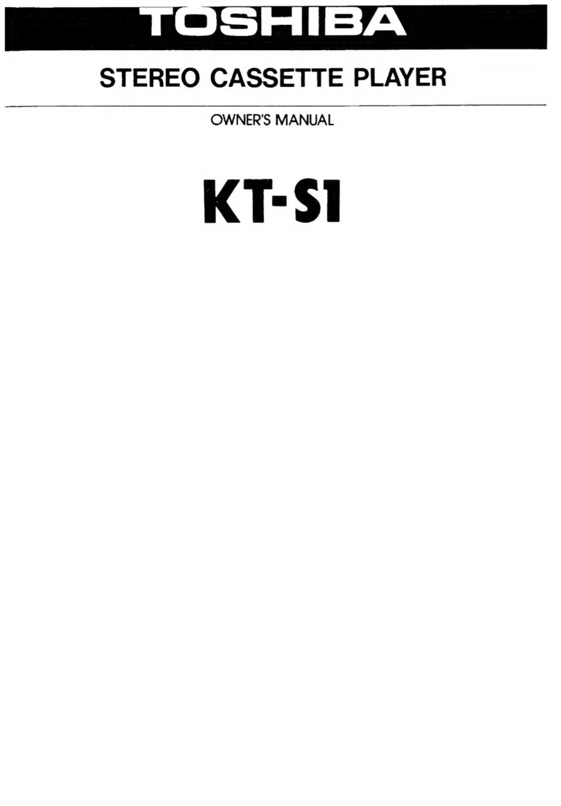
Toshiba PC-X88AD Mounting instructions

Toshiba

Toshiba PC-X88AD Mounting instructions

Toshiba PC-E70 User manual

Toshiba

Toshiba PC-E70 User manual

Toshiba KT-4568 Mounting instructions

Toshiba

Toshiba KT-4568 Mounting instructions

Toshiba KT-S1 User manual

Toshiba

Toshiba KT-S1 User manual

Toshiba SD-V280 User manual

Toshiba

Toshiba SD-V280 User manual

Toshiba RT-S652 User manual

Toshiba

Toshiba RT-S652 User manual

Toshiba SD-V594SU User manual

Toshiba

Toshiba SD-V594SU User manual
Toshiba SD-22VB User manual

Toshiba

Toshiba SD-22VB User manual

Toshiba D-VR660KU User manual

Toshiba

Toshiba D-VR660KU User manual

Toshiba KT-S1 Mounting instructions

Toshiba

Toshiba KT-S1 Mounting instructions
Toshiba RT-S933 User manual

Toshiba

Toshiba RT-S933 User manual
Toshiba RT-200S Mounting instructions

Toshiba

Toshiba RT-200S Mounting instructions

Popular Cassette Player manuals by other brands

Sony Walkman WM-EX9 operating instructions

Sony

Sony Walkman WM-EX9 operating instructions

Sony Walkman WM-FX675 user manual

Sony

Sony Walkman WM-FX675 user manual

Sony walkman WM-EX348 operating instructions

Sony

Sony walkman WM-EX348 operating instructions

Sony CFS-B5SMK2 Service manual

Sony

Sony CFS-B5SMK2 Service manual

JVC Instructions instruction manual

JVC

JVC Instructions instruction manual

Aiwa HS-H09 Service manual

Aiwa

Aiwa HS-H09 Service manual

Dual C839RC operating instructions

Dual

Dual C839RC operating instructions

NAD 616 Specification sheet

NAD

NAD 616 Specification sheet

Sharp GF-770Z Operation manual

Sharp

Sharp GF-770Z Operation manual

Aiwa HS-RX490 Service manual

Aiwa

Aiwa HS-RX490 Service manual

Samsung TW20P14X/BWT Service manual

Samsung

Samsung TW20P14X/BWT Service manual

Panasonic RX-FT510 operating instructions

Panasonic

Panasonic RX-FT510 operating instructions

Aiwa HS-TA164 YJ1 Service manual

Aiwa

Aiwa HS-TA164 YJ1 Service manual

Philips AW7290 user guide

Philips

Philips AW7290 user guide

Panasonic RQ-SX53 operating instructions

Panasonic

Panasonic RQ-SX53 operating instructions

Sony CFS-1045S Service manual

Sony

Sony CFS-1045S Service manual

Atari 1010 Field service manual

Atari

Atari 1010 Field service manual

Optimus SCP-98 owner's manual

Optimus

Optimus SCP-98 owner's manual

manuals.online logo
manuals.online logoBrands
  • About & Mission
  • Contact us
  • Privacy Policy
  • Terms and Conditions

Copyright 2025 Manuals.Online. All Rights Reserved.