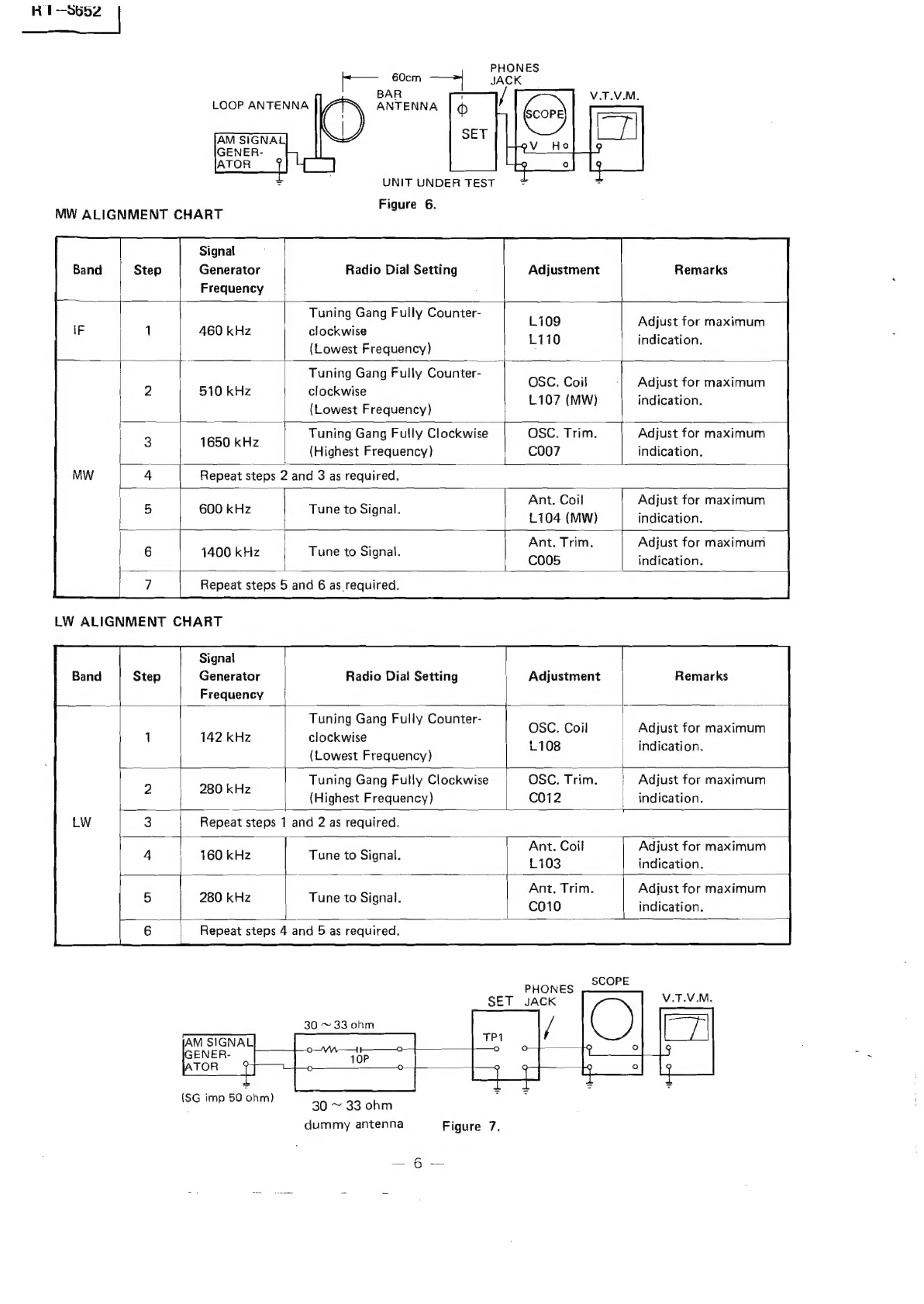
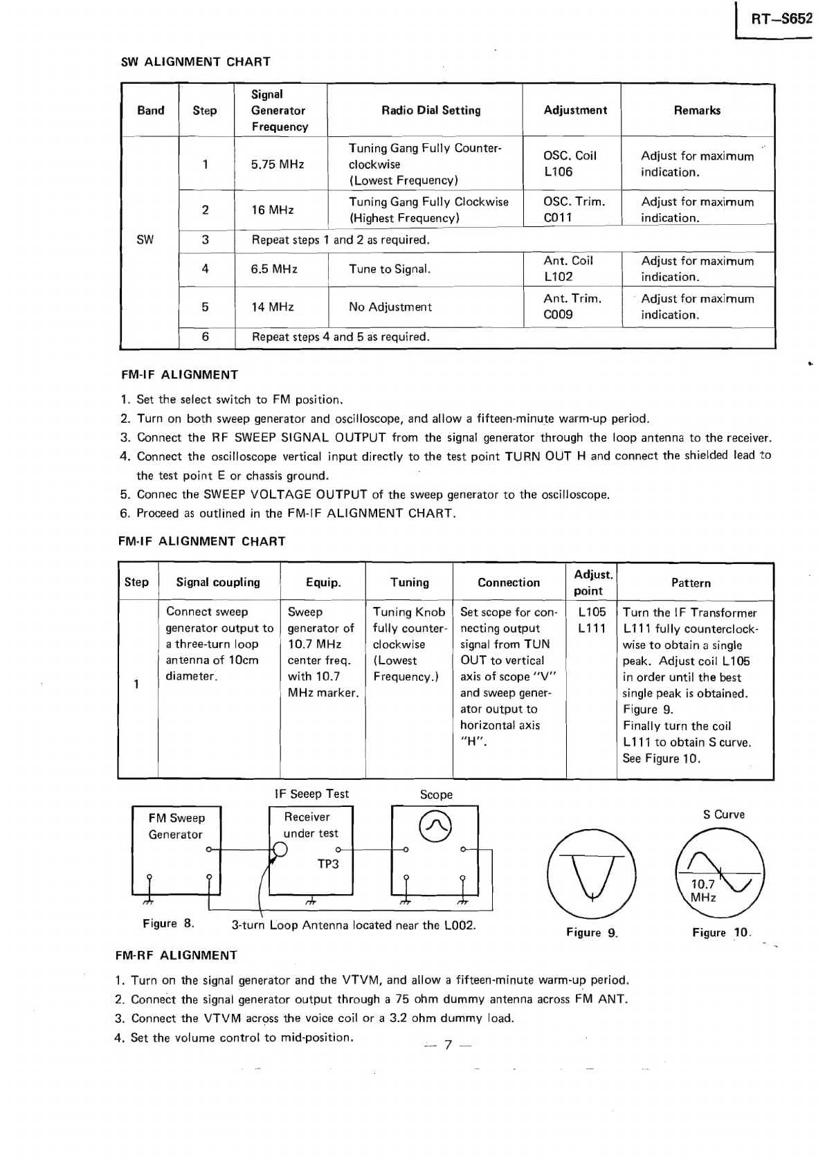
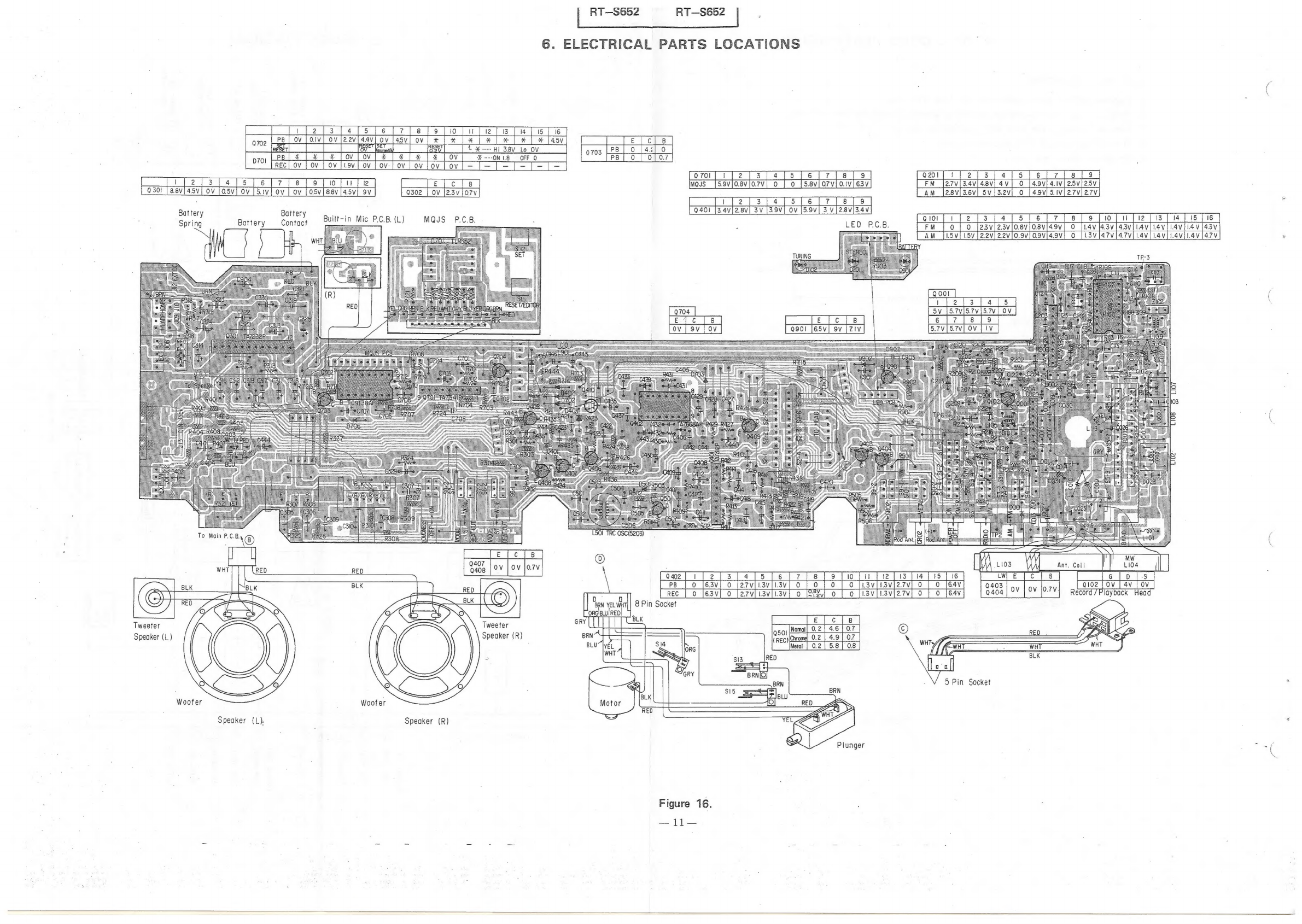
Toshiba RT-S652 User manual

Jgo
SERVICE
DAT.
FILE
NO.
110-288
TOSHIBA
STEREO
RADIO
CASSETTE
RECORDER
HT-S692

1—3002
CONTENTS
1.
OPERATING
CONTROLS
.....
0.20...
0...
cee
ce
eee
3
2.
DISASSEMBLY
INSTRUCTIONS
...........
0000
eee
ee
eee
4
3.
ALIGNMENT
INSTRUCTIONS
.......
0...
0.
ce
eee
eee
eens
5
to
8
4.
DIAL
CORD
RESTRINGING
..........
0...
ee
eee
9
9:
“BEOCK
(DIAG
RAM
ik
ieicr
cece.
hace
siento
de
bans
Maures
«oe
eee
tetera
le
aigta
ete
tate
10
6.
ELECTRICAL
PARTS
LOCATIONS...........
0.000:
e
eee
eee
e
eens
11
7.
SCHEMATIC
DIAGRAM..........
Mlteasiapecenthaste
ples
tet
Abgoeee
ah
Roa
ects,
leat
Biel
ae
AGS
12
8-1.
MECHANISM
EXPLODED
VIEW
(UPPER)...........
00.
0ce
ee
ueeeeuee
13
8-2.
MECHANISM
EXPLODED
VIEW
(LOWER)
..........
0.2002
e
ee
ee
eaee
14
9.
MECHANISM
PARTS
LIST.........
0...
cece
ee
tee
15
10.
CABINET
EXPLODED
VIEW
.........
cee
et
ne
16
11...
CABINET
PARTS
LIST
oo...
nie
eee
eae
Ge
ee
eee
ee
ee
ee
17
12...
“PARTS
PEIST
sor
cvecisauds
sede
toe
aed
2b
aneniae
Uae
ere
dd
avid
ways
18
to
21
Nameplate

|
RT—S652
1.
OPERATING
CONTROLS
CONTROL
FUNCTIONS
OOS
©
®@®O™®
@©®
©
)
@)
©
@
©®
®
@
[AM]
BAND]
Selector
42)
[LOUDNESS]
Button
When
listening
to
low
level
sound,
press
this
buiton,
(2)
[FUNCTION]
Selector
The
treble
and
bass
tones
are
amplified
to
give
a
more
@)
FUNCTION
[ON-OFF/TAPE]
Selector.
natural
sound.
Note:
When
the
accessory
AC
adaptor
is
used,
it
will
be
left
powered
even
when
the
[FUNCTION]
selector
of
the
recorder
is
set
to
OF
F/TAPE.
[TONE]
Control
When
the
recorder
is
not
to
be
used,
be
sure
to
(8)
[BALANCE]
Control
unplag
the
AC
adaptor
from
its
outlet.
G3)
[VOLUME]
Control
Built-in
Microphones
@
[TAPE]
Selector
)
Tweeters
(Speakers
for
high-pitched
sound)
[TAPE]
selector
Woofers
(Speakers
for
iow
to
mid-range
sound)
CrO2
METAL
:
t
METAL
=
[BATTERY]
Indicator
cro,
7s
@0
[FM
STEREO]
Indicator
ees
com
@)
[TUNING]
Indicator
Note:
!f
the
[
D238]
button
is
left
depressed,
the
CrOz,
@)
Tape
Counter
and
Counter
Reset
Button
NORMAL
position
will
not
be
selected
even
when
@
MTSS
[SET]
Button
the
[CrO,]
button
is
pressed.
(5)
[/ASTOP/EJECT]
Button
(6)
[PONE
TOUCH
RECORD]
Button
@
[>>
REVIEW/REW)
Button
[<PLAY]
Button
()
{«
FF/CUE]
Button
4)
MTSS
[RESET/EDITOR]
Button
@5)
[REC]
Indicator
6)
[MTSS]
Indicator
@?)
Tuning
Knob
[MIC]
Jacks
Microphones
with
3.5
mm
plugs
[11PAUSE]
Button
@9
[REC/PB]
Jack
a)
[MODE/BEAT]
Selector
@
[EXT
SPEAKER]
Jacks
Input
impedance
from
3.2
to
8
ohm
[MODE/BEAT]
selector
__MONO
__
|[STEREO-WIDE
Gi)
[PHONES]
[T]
Jack
MONO
62)
[PHONES]
[2]
Jack
STEREO
r
STEREO-WIDE
63
[DC
9
V]
Jack
=
When
accessory
AC
adaptor
is
to
be
used,
connect
it
to
~
this
Jack.
Note:
If
[MONO]
button
is
left
depressed,
the
STEREO,
STEREO-WIDE
mode
will
not
be
selected
even
G4
Telescopic
Antenna
when
the
[STEREO-WIDE]}
button
is
activated.

~
RT-S652
|
1.
2.
Unscrew
two
screws
(A)
and
five
screws
(8).
Fig.
1.
.
Open
the
cassette
cover
by
pressing
the
Stop/Eject
CASSETTE
MECHANISM
ASS’Y
REMOVAL
1.
Follow
the
instruction
for
Front
Cabinet
Removal.
MAIN
P.C.
BOARD
REMOVAL
1.
Follow
the
instruction
for
Front
Cabinet
Removal.
NS
om
F
Ww
.
Disconnect
the
speaker
and
MQJS
connectors
to
.
Reassemble
in
the
reverse
order.
.
Unscrew
one
screw
(C).
Fig.
2.
.
Diconnect
the
Motor
and
the
Head
connectors
©).
.
Take
off
the
Cassette
Mechanism
Ass’y
from
the
Back
.
Pull
out
the
Balance,
Tone,
Volume,
Loudness,
Mode,
.
Pull
up
the
Main
P.C.
Board
from
the
Back
Cabinet.
.
Reassemble
in
the
reverse
order.
DTBID
Hd.
Tapping
3d
x
10mm&
RED
2.
DISASSEMBLY
INSTRUCTIONS
¢———p>
FRONT
CABINET
REMOVAL
DTBID
Hd.
Tapping
3d
x
52mm
Pull
out
the
Tuning
and
Fine
Tuning
Knobs.
button.
separate
the
Front
Cabinet
from
the
Back
Cabinet.
DTBID
Hd.
Tapping
3d
x
35mm
BLK
Figure
1.
Fig.
2.
Cabinet.
Reassemble
in
the
reverse
order.
DTBID
Hd.
Tapping
3d
x
20mm
RED
Figure
2.
DTBID
Hd.
Tapping
3d
x
16mm
RED
Tape
Selector,
Function
and
Band
Switch
Knobs.
Remove
the
spring
©.
Fig.
3.
Unscrew
four
screws
()
and
two
screws
@.
Fig.
3.
Figure
3.

|
RT—S652
3.
ALIGNMENT
INSTRUCTIONS
fe
L193
Re
Ant,
Coil
h
awe!
i
.
TP2
TPI
FM
IN
LW
Ant.
SW
Ant.
colo
co09
@Xo)
ae
‘
eTP6
Free
Run
re
.
Ose.
ue
R203
.
TP4
SW
Ose.
(e)
Free
Run
Sw
“le
AM
IF
L109
Zz)
AM
IF
FM
IF
LIII
euo
DET.
Output
‘Zz
TP3°
}
Figure
4.
TEST
EQUIPMENT
.
Signal
generator
with
a
frequency
range
of
at
least
from
140
kHz
to
23
MHz
AM.
.
Oscilloscope
with
a
side
range
amplifier
of
approximately
100
kHz.
.
Test
loop
—
a
coil
of
any
size
wire,
one
turn
or
more.
(LW
&
MW)
.
A
30
ohm
dummy
antenna.
(SW)
VTVM
a
hwWN
=
AM
ALIGNMENT
.
Turn
on
the
AM
signal
generator
and
the
VTVM
allowing
a
fifteen-minute
warm-up
period.
.
Using
the
test
loop
across
the
output
of
the
signal
generator,
inductively
connect
the
signal
generator
to
the
radio.
.
Connect
the
VTVM
across
the
voice
coil
or
a
3.2
ohm
dummy
load.
PWN
=
.
Set
signal
generator
frequency
as
listed
in
ALIGNMENT
CHART
and
maintain
a
sufficient
output
level
to
provide
an
indication
on
VTVM.
a
Set
volume
contro!
at
mid-position.
6.
Proceed
as
outlined
in
the
IF-LW,
MW
and
SW
ALIGNMENT
CHART.
AM
460kHz
ONE-TURN
COIL
Figure
5.

R1—-s652
|
AM
SIGNAL
GENER-
ATOR
if
=
;
UNIT
UNDER
TEST
Figure
6.
MW
ALIGNMENT
CHART
eS
Signal
Generator
Frequency
Radio
Dial
Setting
Tuning
Gang
Fully
Counter-
clockwise
(Lowest
Frequency)
460
kHz
}-—-—
PHONES
JACK
Adjustment
$$}
—__.
Remarks
Li09
L110
Adjust
for
maximum
indication.
Tuning
Gang
Fully
Counter-
clockwise
(Lowest
Frequency)
510
kHz
OSC.
Coil
L107
(MW)
Adjust
for
maximum
indication.
Tuning
Gang
Fully
Clockwise
peak
(Highest
Frequency)
OSC.
Trim.
C007
Adjust
for
maximum
indication.
R
2
3
ired.
eae
epeat
steps
2
and
3
as
require
600
kHz
Tune
to
Signal.
Ant.
Coil
L104
(MW)
Adjust
for
maximum
indication.
1400
kHz
Tune
to
Signal.
Ant.
Trim.
C005
Adjust
for
maximum
indication.
Repeat
steps
5
and
6
as
required.
LW
ALIGNMENT
CHART
Signal
Generator
Frequency
Radio
Dial
Setting
Adjustment
Remarks
Tuning
Gang
Fully
Counter-
|
clockwise
(Lowest
Frequency)
142
kHz
OSC,
Coil
L108
Tuning
Gang
Fully
Clockwise
280
kHz
(Highest
Frequency)
OSC.
Trim.
C012
Adjust
for
maximum
indication.
Adjust
for
maximum
indication.
Repeat
steps
1
and
2
as
required.
160
kHz
Tune
to
Signal.
Ant.
Coil
L103
Adjust
for
maximum
indication.
280
kHz
Tune
to
Signal.
Ant.
Trim.
C010
Adjust
for
maximum
indication.
t.
Repeat
steps
4
and
5
as
required.
30
~
33
ohm
30
~
33
ohm
dummy
antenna
Figure
7.
_="G
2s:

|
RT—S652
SW
ALIGNMENT
CHART
Signal
Generator
Radio
Dial
Setting
Adjustment
Remarks
Frequency
Tuning
Gang
Fully
Counter-
5.75
MHz
clockwise
(Lowest
Frequency)
OSC.
Coil
Adjust
for
maximum
‘
L106
indication.
Tuning
Gang
Fully
Clockwise
OSC.
Trim.
Adjust
for
maximum
Toe
(Highest
Frequency)
C011
indication.
Repeat
steps
1
and
2
as
required.
Ant.
Coil
Adjust
for
maximum
L102
indication.
Ant.
Trim,
’
Adjust
for
maximum
Ccoo9
indication.
6.5
MHz
Tune
to
Signal.
14
MHz
No
Adjustment
Repeat
steps
4
and
5
as
required.
FM-IF
ALIGNMENT
.
Set
the
select
switch
to
FM
position.
.
Turn
on
both
sweep
generator
and
oscilloscope,
and
allow
a
fifteen-minute
warm-up
period.
.
Connect
the
RF
SWEEP
SIGNAL
OUTPUT
from
the
signal
generator
through
the
loop
antenna
to
the
receiver.
.
Connect
the
oscilloscope
vertical
input
directly
to
the
test
point
TURN
OUT
H
and
connect
the
shielded
lead
to
the
test
point
E
or
chassis
ground.
:
5.
Connec
the
SWEEP
VOLTAGE
OUTPUT
of
the
sweep
generator
to
the
oscilloscope.
6.
Proceed
as
outlined
in
the
FM-IF
ALIGNMENT
CHART.
PWN
=
FM-IF
ALIGNMENT
CHART
Signal
coupling
Equip.
Tuning
Connection
Pattern
Connect
sweep
Sweep
Tuning
Knob
|
Set
scope
for
con-
Turn
the
!F
Transformer
generator
output
to
|
generator
of
|
fully
counter-
|
necting
output
L111
fully
counterclock-
a
three-turn
loop
10.7
MHz
clockwise
signal
from
TUN
wise
to
obtain
a
single
antenna
of
10cm
center
freq.
(Lowest
OUT
to
vertical
peak.
Adjust
coil
L105
diameter.
with
10.7
Frequency.)
axis
of
scope
“V"’
in
order
until
the
best
MHz
marker.
and
sweep
gener-
single
peak
is
obtained.
ator
output
to
Figure
9.
horizontal
axis
Finally
turn
the
coil
“H",
L111
to
obtain
S
curve.
See
Figure
10.
IF
Seeep
Test
FM
Sweep
Receiver
S
Curve
Generator
under
test
ae
aS
Figure
8.
-
F
igure
3-turn
Loop
Antenna
located
near
the
LOO2.
Figure
9.
Figure
10.
FM-RF
ALIGNMENT
1.
Turn
on
the
signal
generator
and
the
VTVM,
and
allow
a
fifteen-minute
warm-up
period.
2.
Connect
the
signal
generator
output
through
a
75
ohm
dummy
antenna
across
FM
ANT.
3.
Connect
the
VTVM
across
the
voice
coil
or
a
3.2
ohm
dummy
load.
4.
Set
the
volume
control
to
mid-position.
7

iT—S652
|
5,
Adjust
the
signal
generator
frequency
as
indicated
in
FM-RF
ALIGNMENT
CHART,
and
maintain
a
sufficient
signal
output
level
to
provide
a
measurable
indication.
6.
Proceed
as
outlined
in
the
FM-RF
ALIGNMENT
CHART.
FM-RF
ALIGNMENT
CHART
Step
Signal
Generator
Radio
Dial
Setting
Adjustment
Remarks
Tuning
Knob
fully
P
: ,
1
87.5
MHz
Counterclockwise
O2G
fol!
AaeE
IO
eal
a
ae
indication.
(Lowest
Frequency)
Tuning
K
full
ee
nob
sully
OSC.
Trim.
Adjust
for
maximum
output
2
108
MHz
Clockwise
C003
indicate
(Highest
Frequency)
pee
3
Repeat
steps
1
and
2
as
required.
4
90
MHz
Ant.
Coil
_
LOO1
Adjust
for
maximum
output
Tune
to
signal
RAGE
indication
nt.
Trim
.
5
106
MHz
;
e
C001
6
Repeat
steps
4
and
5
as
required.
Headphone
SET
Jack
DUMMY
ANTENNA
50
ohm
FREE
RUN
FREQUENCY
ALIGNMENT
Adjust
R203
under
no
signal
condition
so
as
to
obtain
38
kHz
+
75
Hz.
CAUTION:
When
realigning
the
FM
Receiving
Frequency,
the
highest
end
of
the
frequency
range
should
not
be
more
than
108
MHz
and
the
lowest
end
of
the
frequency
range
should
not
be
less
than
87.5
MHz,
in
order
to
comply
with
FTZ
regula-
tions
in
West
Germany.
RECORD/PLAYBACK
HEAD
ADJUSTMENT
A
6.3
kHz
test
tape
must
be
used
for
this
adjustment.
Connect
a
VTVM
or
an
oscilloscope
to
the
headphones
jack
or
speaker
terminal
and
adjust
the
azimuth
by
using
a
phillips
screwdriver
to
maintain
the
maximum
output
voltage.
TAKE-UP/SUPPLY
REEL
TENSION
1.
Insert
cassette
torque
meter
(HARTAK
X-87
Torquette).
Figure
11.
Frequency
V.T.V.M.
Counter
3.2
ohm
Figure
12.
Record/Playback
Head
Record/Playback
Head
Adjustment
Figure
13.
2.
Press
PLAY
button
and
read
torque
meter.
Torque
should
be
35
to
65
gcm.
3.
Release
PLAY
button
and
press
REWIND
button.
Torque
should
be
60
to
160
gcm.
!f
necessary,
clean
take-up
reel
or
drive
belt
with
alcohol,
or
replace
belt.

5.
BLOCK
DIAGRAM
RT—S652
RT—S652
4.
DIAL
CORD
RESTRINGING
Aojdsip
wosbolg
02ju04
U01j9248g
0
=
|
ete
sobunig
dwo
sem0g
Jaypeds
ADM
2
]
E
|
i
(4)
lewpy9
al
<eil
uno
a
un
avasauv1
|
dwo
duo
ad
J8Zyonbe
¥9DGhd|g
ro
(+)
SIN
Ut
-a1ing
©
Jeydads
ouseyxe
()
(4)
jeuup4y9
|
t
Lt
TOsDoipur
()
SIN
[owe
J
4ayyog
‘YQ
jouaixg
——,_4
Jojo
nbay
induy
@u7
JeyDads
jpusayxa
4
(7)
seuubyg
|
#
indyno
aui4
(4)
[euuby9
t
Lo
|
s9yDeds
kom
2
}
2
x
=
(1)
feuuoy
B
|
anor
en
eve
RS
=
<Zuin
YG
prey
toigsay
£
O
o
=
6—{-b)
IW
ul-ning
Le
2°
dup
ag
|
+
auoydpoey
Oo
0.90
090
0
b
ao
z
—
|
Oty
10W2Ix3
oIW
|
’
bulxiy
[|
4
©
yndul
3ul]
O
O_O
g
|
}
(O)
Indjno
3ur]
(7)
yeuuby9
1
40)D91pUl
404D91p
uy
|
Wo
aul]
—
olpoy
“¢
Bujpiosay
—
yooqhd|
J
“Zz
ado)
devervl
dvOv9.vl
dGeelvi
UO~J8M0q
—
}40
-1aM0¢§
‘|
XdW
W3
dw
4f
pua
jody
WV/W4
Wa
4
YOUMS
(
2
turns
Ve
<>
-
Cement
after
tying
twice.
Eyelet
uu
3mm.
s
Cut
less
than
Drum
Figure
14.
9
Dial
cord
363
+
0.5
mm
Spring
4.
Turn
the
tuning
shaft
fully
counterclockwise.
5.
Set
the
pointer
to
the
cord.
—
o
2
£
3
Q
-
c
i
bo2)
=
a)
=
a)
°
°
aad
ro
°
®
go
a
3
°
x
oO
¢c
®
n
~
2.
Wind
the
dial
cord
in
numerical
order
after
passing
through
the
hole
of
drum.
1.
Turn
the
shaft
of
poli-variable
capacitor
fully
clockwise.
3.
Hook
the
spring
to
the
drum
after
completing
winding.
DIAL
CORD
STRINGING

eee:
[3
Q702
D701
ov
[Oiv
[ov
2.2v
|
|
RT—S662
RT—S652
|
,
6.
ELECTRICAL
PARTS
LOCATIONS
pa
|
o
[42|
0
703
[2
PB]
o
|
olor
Lov
|
ov
tf
2a
7)
es
[ofolute
030!
|
8.8V
3
=
5
[6
4.5v[
ov
[os5v[
ov
[5iv
Ov
|
OV
|
05V|
B8V
145V}
9V
E
cls
Tweeter
Speaker
(L)
Battery
Spring
Battery
Battery
Contact
Speaker
(L).
Built-in
Mic
P.C.B.
(L)
Woofer
Q302
|
OV
|2.3VjO7V
Speaker
(R)
MQJS
P.C.B.
fem Ble
ince
a5
Q407
Tweeter
Speaker
(R)
o7oi[
1/2];
3
[4/5
[é6[7][alfo
Mos
|S59vjoevjo7v]
o
|
o
[s8viorvioivi6sv)
3.4V|2.8V|
3V
fe
jec
]e]
1501
TRC
OSC(5203)
ee
eae
ae
ref
0
fesv]
o
farviiaviiav{
0
{9
[0
|
0
faviisvle
Figure
16.
earl
i
[2{[3[4][5]6
8
|
9
FM
[27v/3.4v/4
25V|25V
AM
27V|27Vj
213
/4[5]6
10
|
tl
[001
|
Pera
wesw
6
[er |e.
[eo]
4.9V}
0
7[8s][o9]|
0
f23vi23vifosviosvl4ov]
0
[lav
l43vi43vi
Lavi
i4avii4v
{i
1.5v
[22v]22v[0.9v]
0.9Vv[4.
L3vl47v[47v[.4v[.4viL4aviiav
7V
Record
fi.
Wo
Ee
EW
€
|
coe
et
OOS
|
EE
a
4v
|
ov
Proybac
Head
5
Pin
Socket

a
External
Mic
Jack
6
Built
-
in
Mic
Jack
(L
)
r
1
1
1
1
External
Mic
.
Jack
Bui
Mic
coos
(sl)
L103
LW
ANT
Erase
Head
G
it
-in
02
0
Bs
i
Normal
Rec
)|
Chrome
[Metal
0102
2SK6I-0
LIOS
FM
IFT
(
582i)
(F)
|
ERE
—VWUVE
mi—ovuwy
|
7.
SCHEMATIC
DIAGRAM
2
0
[23v/23v[o.evjosv|4sv|
0
FMIF
Amp.
(pees
DIOL
Isisssv
S07
(5343)
pal
ag
(5388)
R104
~—
122K
122
ee
(F)
W
Sozoif
RIO3
(2k
RLS
8.2K
te
aw
:
OT
7102
IOS
AM
IFT
RIO6 C109
TA7343_
FM
MPX
i
RIO?
Houzbous
“47
lam
&
(2921)
R416
10K
C4l0z8
3.3/50
Coed
tos
6
ISISSSV
[At
mais]
||
Peers]
Pp
D4
a
Bae
C4{t-~41
i
a)
L902
\.SaH
Figure
17.
ca
|e
ae
eee
1815
2SC2655
1
TA
7335P.
TA7343P
TA7312P
TA7341P
TC9138P
aa
03
eq
Tweeter
(L)
@e
:
SW
Tweeter
(L)
s
oo
a
oe
Voter
(R)
Switch
Position
SW.
NO
Now
Si-1
|POWCR
OFF
OFF
SI-6
TAPE
TAPE
ee
PLAY
—
REC
PLAY
s3-!
|
R
53-3
ADIO
—
LINE
IN
RADIO
oe
AM
-
FM
AM
sou
LW-MW-
SW
SW
$5-6
S6-1
STEREO
-
ST
WIDE
=
TERERS
MOND
ees
S7-1
$
=
s7-2
BEAT
PTEREO
$8-1
LOUDNESS
$8-2
OFF
-
ON
OFF
88
Ae
NORMAL
-
CrO2
NORMAL]
ssl
CrO2-
METAL
Cr0e
sit
|
MQUS
RESET/
EDITOR
si2
|
MQUS
SET
S$i3
Power
Leaf
si
Pause
Leaf
Sis
MQUS_
Leaf
J10
Headphone
Jack
2
J09
Headphone
Jack
|
a7o2
TC9I13B8AP
Block
Diagram
J07
Vee
GRO
External
Speaker
Jack
{L)
J08
External
Speaker
R)
wo4
q
Tweeter
(R)
+
SUM-2x6
pcs
NOTE
Ji2-
|,
Resistance
is
shown
in
ohm,
1/4W
External
D.C.
;
K
=
1000
Jack
2
Capacitance
volues
are
expressed
in
pF.
SOV
P=75)
,
10
ae
hese
3.
Electrolytic
capacitor
is
expressed
as
mene
follows
:
;
/
[Ret
©
mic
Caos
ai
100/16
Capacitance
(uF
)
R904
4.
Mark
—
shows
a
safety-related
parts,
5.6K
Be
sure
to
use
designated
parts,
bechd
$14
Pouse Leaf
S15
MQUS
Leaf
9
16
56
B
1234
;
76
TA7232P
TA7640AP
*34
TA7668AP
TLR352

|
RT—S652
K1—S65Z
|
8-1.
MECHANISM
EXPLODED
VIEW
(UPPER)
8-2.
MECHANISM
EXPLODED
VIEW
(LOWER)
2
38
|
S
P°
3
—«
112
110
114
:
Excluded
parts
in
the
Parts
List
are
not
available
NOTE:
Excluded
parts
in
the
Parts
List
are
not
available
as
replacement
parts.
:
Figure
18.
Pp
Pp
:
Figure
19.
as
replacement
parts.
—13—
Ae

Symbol
No.
Part
No.
9.
MECHANISM
PARTS
Description
Symbol
No.
LIST
Part
No.
|
RT—S652
Description
Cc
ASSETTE
MECHANISM
PARTS
22217406
22218245
25791538
25717532
25717533
25755548
25755549
25755562
25873263
25761327
25776484
25776487
25779276
25779282
25741942
25741943
25741944
25741945
25741946
25741947
25741948
25748919
25748927
25756307
25756308
25766050
25776488
25776489
25776493
25776494
25776521
25777182
25778040
25779278
25782546
25782549
25782552
25782555
25782560
25783211
25783239
25778048
25782554
25778047
25778049
25782543
25727270
25754425
25754439
25756305
25766050
25776482
Head,
Record/Playback,
HRPT406
Head,
Erase,
HET62
Motor
Ass’y
Flywheel
Ass’y
Pressure
Roller
Belt,
Drive
Belt,
Center
Belt,
Counter
Counter
Cushion,
Motor
Spring
Spring
Spring,
REC
Spring,
Holder
Type
Operation
Plate,
Lock
Operation
Plate,
Stop
Operation
Plate,
Fast
Forward
Operation
Plate,
Play
Operation
Plate,
Pause
Operation
Plate,
Record
Operation
Plate,
Rewind
Lever,
Cue
Lever,
Release
Cam
Gear,
Pause
Cam
Gear,
Play
Washer
Spring
Spring
Spring
Spring
Spring
Spring,
Pause
Lock
Lever
Spring,
Cue
Lever
Spring,
Operation
Plate
Lever,
Pause
Lock
Lever,
Play
Drive
Lever,
Select
Lever,
Play
Gear
Lock
Pause
Lock
Bushing
Bushing
Spring,
Pause
Gear
Lock
Lever
Lever,
Pause
Gear
Lock
Spring,
ASO
Pause
Lever
Spring,
Cue
Support
Lever,
ASO
Pause
Spring
Pin,
Plunger
Reel
Plate,
Supply
Spacer
Gear,
Rewind
Washer
Spring
61
62
63
64
65
66
67
68
69
70
71
72
73
74
75
76
78
80
81
82
83
84
85
87
88
89
90
91
92
93
97
98
99
25776492
25777144
25778042
25783260
25783226
25712423
25713561
25712412
25782551
25756304
25778045
25782547
25756306
25778044
25782548
25778041
22707833
25777137
25778038
25778043
25781250
25782558
25725340
25766043
25776483
25778039
25782545
25782557
25791529
25776481
25756310
25766073
25776490
25776491
25782561
25757130
25778046
25782550
22707299
22707350
22707747
22707869
22707870
25783294
22707301
25782556
22707426
25791539
25735266
25782553
Spring
Spring
Spring,
Pressure
Roller
Bushing,
BLK
Bushing
Reel
Plate,
Take-up
Center
Clutch
Ass‘y
Gear
Ass’y
,
Take-up
Lever,
Take-up
Gear,
Rewind
Spring,
Rewind
Lever
Lever,
Rewind
Gear,
Fast
Forward
Spring,
FF
Lever
Lever,
Fast
Forward
Spring,
Head
Slider
Screw,
Special,
2d
x
9mm
Spring,
Azimuth
Spring,
Erase
Head
Lever
Spring,
Head
Mtg.
Plate
Head
Mtg.
Plate
Lever,
Erase
Head
Holder,
Flywheel
Washer
Spring
Spring,
REC
Lock
Lever
Lever,
Record
Lever,
Record
Lock
Slider
Ass’y,
Record
Spring
Gear,
ASO
Washer
Spring
Spring
Interlocking
Lever,
ASO
Steel
Ball,
5mmd
Spring,
ASO
Detect
Lever
Lever,
ASO
Detect
Screw,
BID
Hd.,
Tapping,
2d
x
8mmk
Screw,
DTBID
H.,
2.6d
x
5mm
Screw,
Special,
Motor
Screw,
BID
Hd.,
Tapping,
2d
x
18mm&
Screw,
PAN
Hd.,
Tapping,
2d
x
8mm
Mtg.
Bracket,
Counter
Screw,
BID
Hd.,
Tapping,
2.6d
x
8mm
Slider,
Eject
Screw,
DTBID
Hd.,
2d
x
5mm&-
Chassis
Ass’y,
Main
Spacer,
Rec.
Head
Lever,
Search

T—S652
10.
CABINET
EXPLODED
VIEW
Excluded
parts
in
the
NOTE:
Parts
List
are
not
available
as
replacement
parts.
Figure
20.

|
RT—S652
11.
CABINET
PARTS
LIST
Symbol
No.|
Part
No.
Description
Symbol
No.
|
Part
No.
}
Description
350
22707802
|
Screw,
BID
Hd.,
Tapping
CABINET
PARTS
3d
x
12mm?
25881478
|
Cabinet
Front
Ass’y
351
22701457
|
Screw,
BID
Hd.,
3d
x
6mm&,
25881479
|
Cabinet
Back
Ass‘y
Chrome
Plated
22741387
|
Pointer
352
22707845
|
Screw,
BID
Hd.,
2.6d
x
8mm,
25776523
|
Sping,
Cabinet
Chrome
Plated
25837799
|
Knob,
Balance
354
22707801
|
Screw,
BID
Hd.,
Tapping
25837800
|
Knob,
Tuning
3d
x
12mm&,
Chrome
Plated
25837941
|
Knob,
Push
356
22707452
|
Screw,
BID
Hd.,
3d
x
5mm
25846572
|
Mtg.
Piece
357
25808281
|
Nameplate,
Main,
TE,
TU
25779253
|
Spring,
Cassette
Cover
357
25808369
|
Nameplate,
Main,
IT
25824436
|
Reflector,
Cassette
25837802
|
Button,
MOJS
25881605
|
Cassette
Cover
Ass’y
25837860
|
Knob,
Band
Select
25844202
|
Damper,
Base
25857072
|
Damper,
Gear
22764018
|
Battery
Spring
25776332
|
Battery
Spring
25777026
|
Battery
Spring
25837829
|
Knob,
Fine
Tuning
25837803
|
Button,
Pause,
Mechanism
25837804
|
Button,
Stop/Eject,
Review/
REW,
FF/Cue
25837805
|
Button,
Record,
Mechanism
25837806
|
Button,
Play,
Mechanism
25825262
|
Handle,
Main
25881375
|
Battery
Cover
Ass’y
22705026
|
Plastic
Rivet,
3d
x
6.5mm
22742016
|
Pulley
22742162
|
Pulley
22742279
|
Dial
Drum
22742287
|
Pulley
with
Shaft
22743306
|
Tuning
Shaft
22743307
|
Retainer,
Tuning
Shaft
25771548
|
Spring
25783226
|
Bushing
25864167
|
Jack
Plate
22707805
|
Screw,
BID
Hd.,
Tapping
3d
x
20mm&k
22707810
|
Screw,
BID
Hd.,
Tapping
3d
x
35mm&k
22707826
|
Screw,
BID
Hd.,
Tapping
3d
x
10mm&
22707841
|
Screw,
BID
Hd.,
Tapping
3d
x
52mm2
22707842
|
Screw,
BID
Hd.,
Tapping
3d
x
8mm
22707843
|
Screw,
BID
Hd.,
Tapping
3d
x
16mm&,
RED
22707844
|
Screw,
BID
Hd.,
Tapping
3d
x
10mm&k,
RED
eS
a

RT—S652
|
CAUTION:
Symbol
No.
12.
PARTS
LIST
The
A
mark,
the
symbol
No.
circled
with
rectangle
in
the
schematic
diagram
and
the
shaded
area
in
the
parts
list
designate
components
which
have
special
characteristics
important
for
safety
and
should
be
replaced
only
with
types
identical
to
those
in
the
original
circuit
or
specified
in
the
parts
list.
Part
No.
Description
Symbol
No.
Part
No.
Description
TRANSISTORS,
ICS
&
DIODES
Q001
Q101
Q102
Q201
0301
0401
0402
0403,
404,
409
Q405,
406,
407,
408
0410
0501
Q701
Q702
Q703
Q704,
901
DOO1,
101
402,
501,
702, 703,
704,
705,
706
D102,
201,
901
D401,
403
D701
D902
B0325270
B0356385
A604
1020
B0325350
B0319960
B0324550
B0356690
A6317460
A6342210
A6534740
A6319300
B0325320
B0411385
A6317480
A6333320
A7246703
A8603140
A7236900
A8621520
A7110023
IC,
TA7335P
IC,
TA7640AP
Transistor,
2SK61-O
IC,
TA7343P
IC,
TA7232P
IC,
TA7312P
IC,
TA7668AP
Transistor,
2SC1815NEW-GR
Transistor,
2SC2878-BL
Transistor,
2SA1049-GR
Transistor,
2SC1959NEW-Y
IC,
TA7341P
IC,
TC9138AP
Transistor,
2SC1815NEW-BL
Transistor,
2SC2655-Y
Diode,
1S1555V
Diode,
LED,
TLR208
Diode,
Zener,
02BZ3.3
Diode,
LED,
TLR352
Diode,
Zener,
0525.1
L902
22291103
Coil,
Choke,
1.5uH
ELECTR
ICAL
PARTS
COILS
&
T
RANSFORMERS
LOO1
LOO02
L101
L102
L103/104
L105
L106
L107
L108
L109
L110
L111
L112
L501
L502
Amana
L901
22294004
22294457
22291103
22282214
22242921
22265821
22285343
22245385
22245389
22264837
22264838
22265822
22291140
22235203
22230106
221A7:
Coil,
FM
Coil,
FM
Coil,
Choke,
1.5uH
Coil,
Antenna,
SW
Coil,
Antenna,
LW/MW
IF
Transformer,
FM
Coil,
Oscillator,
SW
Coil,
Oscillator,
MW
Coil,
Oscillator,
LW
IF
Transformer,
AM
IF
Transformer,
AM
IF
Transformer,
FM
Coil,
Choke
Coil,
Oscillator,
Tape
Bias
Coil,
Choke,
471F
=
ie
al
$13
$14
$15
J1/J2
J3
to
J6
J7/J8
J9/J10
J12
J13
G01,
02
A01,
02
Ww01,
02
W03,
04
Z001
2101
2102
22196145
22196071
22195955
22196073
22196069
22196064
22196063
22196063
22163950
22163887
22163950
22163951
22163721
22167975
22154233
22124485
22152413
22152425
22153121
22153058
22153083
Switch,
Slide,
Within
$3,
S4,
$9
and
S10
$1:
POWER
OFF
TAPE
-POWER
ON
$3:
RADIO-LINE
IN
S4:
AM-FM
$9:
NORMAL-Cr02
$10:
CrO2-METAL
Switch,
Slide,
Record/
Playback
Switch,
Lever,
LW-MW-SW
Switch,
Push,
STEREO-
SPACE
WIDE
Within
S7
and
$8
S7:
STEREO-MONO
(BEAT)
S8:
LOUDNESS
OFF-ON
Switch,
Key,
RESET/
EDITOR
Within
S12
$12:
MOJS
SET
Switch,
Leaf,
Power
ON-OFF
Switch,
Leaf,
Pause
Switch,
Leaf,
MQJS
Jack,
Ext.
Mic.,
R/L,
3.5mmd
Jack,
US-4P,
RADIO-LINE
Jack,
Ext.
Speaker,
3.5mmd
Jack,
Headphone,
3.5mmd
Jack,
DC
Power
Jack,
DIN-5P
Built-in
Microphone
Rod
Antenna
Speaker,
Woofer,
100mm
Speaker,
Tweeter,
20mm
Filter,
FM
Bypass
Filter,
Ceramic,
FM
Filter,
Ceramic,
460B,
AM

|
RT—S652
|
Symbol
No.
Description
Symbol
No.|
Part
No.
|
Description
C203
22321032}
PF,
1000pF,
K
CAPACITORS
=
C204
22488109
EL,
1mfd,
50V
Voltage
Ratings
of
Ceramic
and
Plastic
Film
Capacitor
C205.
206
22360328
|
PF.
0.015mfd.
M.
25V
are
50V
DC
unless
einenee
noted.
:
C207,
208
22360324
|
PF,
3300pF,
M,
25V
Soe
Oye
Va
eee
ey
ee
oe
errae
C209,
210
|
22488339]
EL,
3.3mfd,
50V
z
C211
22483101)
EL,
100mfd,
10V
C212
22483470!
EL,
47mfd,
10V
C213
22488339
|
EL,
3.3mfd,
50V
C001,
002,
|
22308219)
Tuning
Capacitor
with
C301,
302
22349102!
CD,
1000pF,
K
003,
004,
Trimmer
C305,
306
22342223
|
CD,
0.022mfd,
Z
005,
006,
C307,
308
22360331)
CD,
0.047mfd,
M,
25V
008
C309,
310
22349222
|
CD,
2200pF,
K
C009
,010
|
22309184]
Trimmer,
LW,
SW,
Ant.
C311,
312
22488339
|
EL,
3.3mfd,
50V
C011
~
012
|
22309184]
Trimmer,
LW,
SW,
Osc.
C313,
314
22483101|
EL,
100mfd,
10V
C013,
014
22342223
|
CD,
0.022mfd,
Z
C315,
316
22483470|
EL,
47mfd,
10V
C015
22342223]
CD,
0.022mfd,
Z
C317,
318
22349332
CD,
3300pF,
K
C016
22360331
|
PF,
0.047mfd,
M,
25V
C319,
320
22372154
|
PF,
0.15mfd,
K
C017
22362220]
CD,
22pF,
K
C321,
322
22349102|
CD,
1000pF
C018
22360696]
CD,
22pF,
J
(CH)
C323,
324
22482471
|
EL,
470mfd,
6.3V
C019
22360694
|
CD,
15pF,
J
(CH)
C325
22485471)
EL,
470mfd,
16V
C020
22361100}
CD,
10pF,
D
C329
22483470)
EL,
47mfd,
10V
C021
22340183]
CD,
0.022mfd,
N
C330
22485220;
EL,
22mfd,
16V
C023
22362101]
CD,
100pF,
K
C401,
402
22360329
|
PF,
0.022mfd,
M,
25V
C025
22360679]
CD,
10pF,
J
C403,
404
22360331
|
CD,
0.047mfd,
M,
25V
C026
22362820]
CD,
82pF,
K
C407,
408
22349102!
CD,
1000pF,
K
C027
22340183]
CD,
0.022mfd,
N
C409,
410
22488339}
EL,
3.3mfd,
50V
C030
22342103}
CD,
0.01mfd,
Z
C411
22485100|
EL,
10mfd,
16V
C031
22342223]
CD,
0.022mfd,
Z
C412
22485100;
EL,
10mfd,
16V
C101
22362270|
CD,
27pF,
K
C413
22360330
|
PF,
0.033mfd,
M,
25V
C102
22362220
|
CD,
22pF,
K
C414
22360330
|
PF,
0.033mfd,
M,
25V
C103
22321222
|
CD,
250pF,
J
C415
22488339
|
EL,
3.3mfd,
50V
C105
22349392]
CD,
3900pF,
K
C416
22488339
|
EL,
3.3mfd,
50V
C106
22321016|
PF,
360pF,
J
C417
22485100
|
EL.
10mfd,
16V
C107
22321048
|
PF,
270pF,
J
C418
22483221
|
EL,
220mfd,
10V
C108
22342103]
CD,
0.01mfd,
Z
C419,
420
22360328
|
PF,
0.015mfd,
M,
25V
C109
22342103]
CD,
0.01mfd,
Z
C421,
422
22360537
|
PF,
2700pF,
K,
25V
C110
22349471]
CD,
470pF,
K
C423,
424
22349472
|
CD,
4700pF,
K
C111
22360329]
PF,
0.022mfd,
M
C425,
426
22360329
|
PF,
0.022mfd,
M,
25V
©
C112
22483101]
EL,
100mfd,
10V
C427,
428
22488339
|
EL,
3.3mfd,
50V
C113
22342223]
CD,
0.022mfd,
Z
C429,
430
22485220
|
EL,
22mfd,
16V
C114
22488339]
EL,
3.3mfd,
50V
C431,
432
22362180|
CD,
18pF,
K
C115
22485100]
EL,
10mfd,
16V
C433,
434
22360332
|
PF,
0.068mfd,
M,
25V
C116
22342223)
CD,
0.022mfd,
Z
C435,
436
22488339
|
EL,
3.3mfd,
50V
C117
22485220]
EL,
22mfd,
16V
C437,
438
22349472
|
CD,
4700pF,
K
C118
22342223
|
CD,
0.022mfd,
Z
C439
22483470|
EL,
47mfd,
10V
C119
22488478]
EL,
0.47mfd,
50V
C440
22483101|
EL,
100mfd,
10V
C120
22488339)
EL,
3.3mfd,
50V
C441,
442
22349472|
CD,
4700pF,
K
C121
22360331]
PF,
0.047mfd,
M
C443
22483331)
EL,
330mfd,
10V
C122
22342223]
CD,
0.022mfd,
Z
C444
22483470|
EL.47mfd,
10V
C123
22349221]
CD,
220pF,
K
C445
22485100/|
EL,
10mfd,
16V
C124
22349331]
CD,
330pF,
K
C446
22483470|
EL
47mfd,
10V
Aas
C201
22488339]
EL,
3.3mfd,
50V
C501
22349271|
CD,
270pF,
K
C202
22488109]
EL,
Imfd,
50V
C502
22349151|
CD,
150pF,
K
Abbreviations:
|
CD
=
Ceramic
Disk,
PF
=
Plastic
Film,
EL
=
Electrolytic
234G.—

RT~S652
|
Symbol
No.|
Part
No.
Description
C503
22321105!
PF,
270pF,
J,
100V
C504
22360321]
PF,
1000pF,
M,
25V
C505
22360325
|
PF,
4700pF,
M,
25V
C506
22349391
|
CD,
390pF,
K
C507
22483470|
EL,
47mfd,
10V
C701
22485100
EL,
10mfd,
16V
C702
22349472
CD,
4700pF,
K
C703
22483470!
EL,
47mfd,
10V
C704
22342223
|
CD,
0.022mfd,
Z
C705
22360332
|
PF,
0.068mfd,
M,
25V
C706
22349392
|
CD,
3900pF,
K
C707
22488339
|
EL,
3.3mfd,
50V
C901,
902
22342223
|
CD,
0.022mfd,
Z
C903
22483471]
EL
.470mfd,
10V
C904
22485222!
EL.
2200mfd,
16V
C905
22342473
|
CD,
0.047mfd,
Z
C906
22485101
|
EL,
100mfd,
16V
Symbol
No.;}
Part
No.
Description
R212
22584104
|
100K
ohm
R213
22545820
|
82
ohm
(PRC)
R214
22545151
|
150
ohm
(PRC)
R215
22584102
|
1K
ohm
R216
22584102
|
1K
ohm
R217
22584470
|
47
ohm
R301
22584223
|
22K
ohm
R302
22584223
|
22K
ohm
R303
22545682
|
6.8K
ohm
(PRC)
R304
22545682
|
6.8K
ohm
(PRC)
R305
22545222
|
2.2K
ohm
(PRC)
R306
22545222
|
2.2K
ohm
(PRC)
R307/
R308)
22624430
|
Variable
50K-A,
Tone
R309
22545272
|
2.7K
ohm
(PRC)
R310
22545272
|
2.7K
ohm
(PRC)
R311/R312|
22625019
|
Variable,
50K-B,
Volume
R313
22584471
|
470
ohm
R314
22584471
|470
ohm
R315
22584101
|
100
ohm
R316
22584101
|
100
ohm
R317
22584101
|
100
ohm
R318
22584101
|
100
ohm
R321
22625018
|
Variable
50K-B,
Balance
R324
22584331
|
330
ohm
R325
22545222
|
2.2K
ohm
(PRC)
R326
22545222
|
2.2K
ohm
(PRC)
R401,
402
22545102
|
1K
ohm
(PRC)
R403,
404
22545
154
|
150K
ohm
(PRC)
R405,
406
22545472
|
4.7K
ohm
(PRC)
R407
22545681
|
680
ohm
(PRC)
R408
22545681
|
680
ohm
(PRC)
R409
22584221
|
220
ohm
R410
22584221
|
220
ohm
R411
22584332
|
3.3K
ohm
R412
22584332
|
3.3K
ohm
R413
22584104
|
100K
ohm
R414
22584
104
|
100K
ohm
R415
22584103
|
10K
ohm
R416
22584103
|
10K
ohm
R417
22545822
|
8.2K
ohm
(PRC)
R418
22545822
|
8.2K
ohm
(PRC)
R419
22545682
|
6.8K
ohm
(PRC)
R420
22545682
|
6.8K
ohm
(PRC)
R421
22545472
|
4.7K
ohm
(PRC)
R422
22545472
|
4.7K
ohm
(PRC)
R423
22545103
|
10K
ohm
(PRC)
R424
22545103
|
10K
ohm
(PRC)
R425
22545562
|
5.6K
ohm
(PRC)
R426
22545562
|
5.6K
ohm
(PRC)
R427
22584225
|
2.2M
ohm
R428
22545102
|
1K
ohm
(PRC)
!
RESISTORS
.
Resistors
are
Carbon
Film
“W,
+5%
unless
otherwise
noted.
.
PRC
is
short
for
the
printed
resistor
circuit.
If
replacement
of
the
resistor
in
PRC
is
required,
please
use
the
substitutional
fixed
carbon
film
resistor
of
“%W,
+5%
according
to
the
following
list.
K
=
1000,
M
=
1000000
R101
22545151
|
150
ohm
(PRC)
R102
22584331
|
330
ohm
R103
22545123
|
12K
ohm
(PRC)
R104
22545223
|
22K
ohm
(PRC)
R105
22545682
|
6.8K
ohm
(PRC)
R106
22545183
|
18K
ohm
(PRC)
R108
22545472
|
4.7K
ohm
(PRC)
R109
22545104
|
100K
ohm
(PRC)
R110
22545224
|
220K
ohm
(PRC)
R111
22545104
|
100K
ohm
(PRC)
R112
22545681
|
680
ohm
(PRC)
R113
22584470
|
47
ohm
R114
22584154
|
150K
ohm
R115
22545822
|
8.2K
ohm
R201
22545102
|
1K
ohm
(PRC)
R202
22545562
|
5.6K
ohm
(PRC)
R203
22658599
|
Semi-fixed
Variable
10K-B,
Free
Run
R204
22545681
|
680
ohm
(PRC)
R205
22584561
|
560
ohm
R206
22584154
|
150K
ohm
R207
22545332
|
3.3K
ohm
(PRC)
R208
22545332
|
3.3K
ohm
(PRC)
R209
22545332
|
3.3K
ohm
(PRC)
R210
22545332
|
3.3K
ohm
(PRC)
R211
22584104
|
100K
ohm

Symbol
No.
Part
No.
Description
Symbol
No.
Description
R429
R430
R431
R432
R433
R434
R435
R436
R437
R438
R439
R440
R441
R442
R443
R444
R501
R502
R503
R504
R506
R507
R508
R701
R702
R703
R704
R705
R706
R707
R708
R709
R710
R711
R712
R713
R714
R715
R716
R717
R718
R719
R720
R721
R722
R723
R724-
22584151
|
150
ohm
22584151
|
150
ohm
22584273
|
27K
ohm
22584273
|
27K
ohm
22584562
|
5.6K
ohm
22584562
|
5.6K
ohm
22545682
|
6.8K
ohm
(PRC)
22545682
|
6.8K
ohm
(PRC)
22545102
|
1K
ohm
(PRC)
22545102
|
1K
ohm
(PRC)
22545102
|
1K
ohm
(PRC)
22545102
|
1K
ohm
(PRC)
22545561
|
560
ohm
(PRC)
22584680
|
68
ohm
22545102
|
1K
ohm
(PRC)
22584334
|
330K
ohm
22545102
|
1K
ohm
(PRC)
22545682
|
6.8K
ohm
(PRC)
22545680
|
680
ohm
(PRC)
22584120
|
12
ohm
22584680
|
68
ohm
22584470
|
47
ohm
22584120
|
12
ohm
22584183
|
18K
ohm
22584104
|
100K
ohm
22545102
|
1K
ohm
(PRC)
22545103
|
10K
ohm
(PRC)
22584101
|
100
ohm
22584681
|
680
ohm
22545102
1K
ohm
(PRC)
22545103
|
10K
ohm
(PRC)
22584151
|
150
ohm
22584274
|
270K
ohm
22545103
|
10K
ohm
(PRC)
22584104
|
100K
ohm
22545102
|
1K
ohm
(PRC)
22545102
|
1K
ohm
(PRC)
22545681
|
680
ohm
(PRC)
22545102!
1K
ohm
22545102
|
1K
ohm
22545102
|
1K
ohm
22545102
|
1K
ohm
22545102
|
1K
ohm
22545102
|
1K
ohm
22584102
|
1K
ohm
22545103
|
10K
ohm
(PRC)
22545102
1K
ohm
(PRC)
220
ohm
(PRC)
6.8K
ohm
(PRC)
5.6K
ohm
22545221
22545682
22584562
ACCESSORIES
|
RT—S652
209
22903401
|
Owner’s
Manual

TOSHIBA
CORPORATION
2-1,
GINZA
5-CHOME,
CHUO-KU,
TOKYO
104,
JAPAN
PRINTED
IN
JAPAN
22905138
Nov.,1982
Other Toshiba Cassette Player manuals

Toshiba
Toshiba KT-4568 Mounting instructions

Toshiba
Toshiba PC-E70 User manual

Toshiba
Toshiba SD-V280 User manual

Toshiba
Toshiba D-VR660KU User manual

Toshiba
Toshiba RT-S933 User manual

Toshiba
Toshiba KT-R2 User manual

Toshiba
Toshiba KT-S1 User manual

Toshiba
Toshiba RT-200S Mounting instructions

Toshiba
Toshiba SD-V594SU User manual

Toshiba
Toshiba SD-22VB User manual