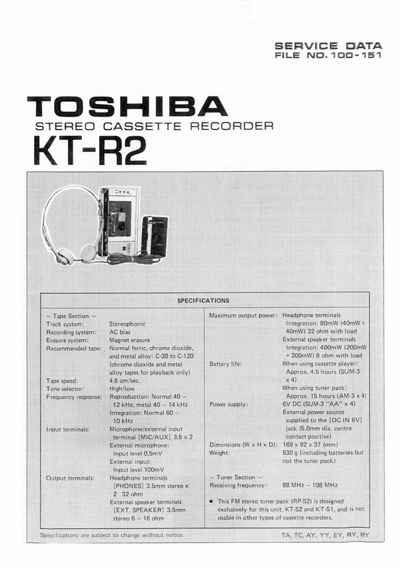
Toshiba RT-200S Mounting instructions

FILE
STEREO
RADIO
CASSETTE
RECORDER

sito
|
RT—200S
CONTENTS
2.
OPERATING
CONTROLS
4.
“BEOCK.
DIAGRAM
:<
i3
a.445
oe
eae
Shee
PO
OSA
es
SS
Pe
a
aes
2
2.
OPERATING
CONTROLS...
2...
0.
eee
ee
es
3
to
7
3.
DISASSEMBLY
INSTRUCTIONS
.......0
0.00
ee
eee
eee
ee
eee
ee
eens
7
to
8
CONTROL
FUNCTIONS
|
4.
HANDLE
REMOVAL
........
2...
cee
eee
ee
eee
ee
ee
eee
8
5.
DIAL
CORD
RESTRINGING
......
cee
ee
ees
8
6.
ALIGNMENT
INSTRUCTIONS
...........
ate
se
ee
Dave
eons
Ane
ee
Wea
a
ee
9
to
12
7.
ELECTRICAL
PARTS
LOCATIONS...
0.0...
0.2
2
eee
ee
ee
ees
13
8
SCHEMATIC
DIAGRAM
........2
0.0
eee
ee
ee
eee
eee
14
9-1.
MECHANISM
EXPLODED
VIEW
(UPPER).......
det
hile,
ete
Cee
Ges
Gy
tds
Bates
eee
ae
15
9-2.
MECHANISM
EXPLODED
VIEW
(LOWER)
.......--
eee
eee
ee
eee
16
10.
MECHANISM
DISASSEMBLY
AND
SET
UP
......-.
eee
ee
eee
eee
17
to
18
11.
MECHANISM
PARTS
LIST........-----!
bp
Lives
Gt
Dacattig
Rt
Se
Se
eee
A
ee
12.
CABINET
EXPLODED
VIEW
......
eee
ce
ee
ee
ees
20
12>
PARTS
UIST
o2s.63
bbe
Sais
6S
eee
SERRA
eR
ee
ERE
See
21
to
24
1.
BLOCK
DIAGRAM
Q001
TA7335P
EM
/AM-TF)
OEM
MEX]
a
ea
Rod
Ant.
°
(FM
RF
OSC
MIX!
i
AM
IN
AM
O
OS)
Band
(
osc)
LIOt
SW
ANT
LI04
Sw2
OSC
6
=
Band
I:
Ces
ose:
Figure
2
L102
MW
ANT
RS)
Lios
MW
OSC
rR
SW
Grawercé)
°
‘s
i:
Band
PP
aly
Q102
A
L103
fw
_/
nibeeewiaee
sf
28€1815
oye
mii
ail
()
Tuning
Knob
(7)
Cycle
Change
Lever
for
AUTO
REVERSE:
‘=
a
1
4)
LINE
OUT
R
e
I:
@
[FINE
TUNING]
Control
1
CYCLE/CONT
are
pean
ry
wx
mic
®
[BAND]
Selector:
LM/MW/SW/FM
“
(channel)
Change
Lever
for
AUTO
REVERSE:
J
A
ANUAL
“
ct.
if
gt
te
@IFUNCTION]
Selector:
RADIO
OFF
TAPEY
te
ata
=
STOP/OPEN]
K
IN
MIC
Leh
GI
2
ears
|
X
>
iq
4
SP
Reh
RADIO/AUX
-
]
Key
ee
Ve
Note:
In
the
RADIO
OFF/TAPE
position
the
Q)
[44
CUE/REVIEW]
Key
~
4
oy
|
HEAD
PHONE
mains
power
will
still
be
supplied.
There-
@
[4PLAY]
Ke
os
a
]
EXT
SPL
fore,
when
not
in
use
unplug
the
cord
from
J
Rec/PB
&D
6%
—.,
RIPPLE
FILTER
Y
peas
|
R
eee
220
Ee
pny
SUM
®
[TAPE
SELECTOR]
Selector:
METAL/CrO,/
2)
[>
PLAY]
Key
ext
mc
TEE
\
77H
ise
NORMAL
@
[>>
CUE/REVIEW]
Key
i
US
oar
gm
ae
Freer
aC
220-240V
SOM:
(6)
[MODE/BEAT]
Selector
5)
[INPAUSE]
Key
AUX
Rech
Cal
BATTERY
T
LEEF
|
1
{@voror
090!
ae
i)
ps1,
lB2C
@
[VOLUME]
Control
Q6)
Tape
Counter
iS
BIAS
OSC
B2cl
18221
[TONE]
Control
@7)
Counter
Reset
Butto
Figure
1.
m
.
()
[TUNING]
Indicator
@
[EXT
SP]
Jacks
Riameniats
Bower
Supely
Cais
()
[FM
STEREO]
Indicator
@9
[LINE
OUT]
Jacks
(Tape
play)
ee
eee
s.
ast
4)
[BATTERY]
Indicator
60
[AUX]
Jacks
gem
TOSHIBA
STEREO
|
foes
RACIO
CASSETTE
(2
Built-in
Microphones
6)
[MIXING
MIC]
Jack
moos.
no.
RT-
2008
(3
[PHONES]
Jack
82
[MIC]
Jacks
CAGE
‘Sw
ans.
aMiez
m
Cf
Raw
SES
segs
()
Tweeters
(Speakers
for
high-pitched
sound)
83
Telescopic
Antenna
a
Sci
(§
Tape
Running
Indicators
@4
Batteries
Compartment
PO”
size
CELLS
fod
rz
pratt
n/e3a
(®
Woofers
(Speakers
for
low
to
mid-range
sound)
65
[AC
POWER]
Socket
TOS*MBA
CORPORATION
MADE
WN
GABA,
PRRIHUET
TE,
TU,
AY
TE
TU

[5|
Recording
with
External
Microphones
Plug
external
microphones
(optional)
into
the
MIC
jacks
62
in
the
rear
of
the
set,
and
then
proceed
in
(6|
Recording
from
other
Audio
Equipment
An
external
amplifier
can
be
connected
to
the
[AUX]
jacks
80
in
the
rear
of
the
set.
To
record,
switch
the
[FUNCTION]
selector
4
to
the
AUX
position,
and
Line
Out
When
another
amplifier
or
tape
deck
is
connected
to
the
[LINE
OUT]
jack
@9
on
the
back
of
the
unit,
tape
sound
can
be
amplified
or
tape
dubbing
(copy-
RT—200S
exactly
the
same
way
as
described
above
for
‘‘Record-
ing
via
Built-in
Microphones.”’
then
proceed
in
exactly
the
same
way
as
described
above
for
‘‘Recording
via
Built-in
Microphones.”
ing)
can
be
performed.
After
connecting
the
cord,
operate
the
unit
according
to
the
sequence
given
in
Listening
to
Tapes.
PLAYBACK
MIXING
When
optional
external
microphone
is
to
be
used,
live
sounds
can
be
mixed
with
sound
from
a
played-
back
tape.
When
connect
it
to
the
[MIXING
MIC]
jack
$1,
the
sound
will
still
be
heard
from
both
left
and
right
speakers.
(The
mixing
microphone
jack
require
3.5
mm
plug.)
3.
DISASSEMBLY
INSTRUCTIONS
FRONT
PANEL
REMOVAL
1.
Remove
8
Knobs
(A)
(Tuning,
Fine
Tuning,
Band,
Function,
Tape
Selector,
Made/Beat,
Volume
and
Tone).
Figure
3.
2.
Remove
7
screws
(B).
Figure
4.
3.
Depress
the
stop/open
button.
4,
Separate
the
front
panel
from
the
back
cabinet.
MECHANISM
ASS’Y
REMOVAL
1.
Remove
3
screws
(C).
Figure
5.
2.
Disconnect
2
leads
wire
(D).
Figure
5.
3.
Separate
the
mechanism
ass'y
from
the
back
cabinet.
LED
P.C.
BOARD
ASS‘'Y
REMOVAL
1.
Remove
4
screws
(E)
and
(F).
Figure
5.
2.
Separate
2
LED
P.C.
Board
(Reverse
and
Forward).
MAIN
P.c.
BOARD’
REMOVAL
1.
Remove
2
tweeter
speakers.
Figure
5.
2.
Remove
2
screws
G)
and
the
hook
of
4P
jack
(AUX,
LINE
OUT).
Figure
5.
3.
Separate
the
main
P.C.
Board
from
the
back
cabinet.
POWER
P.C.
BOARD
REMOVAL
1.
Remove
2
screws
(H).
Figure
5.
2.
Separate
the
power
P.C.
Board
from
the
back
cabinet.
_—
Figure
3.
y
BID
¢3
x
20mm
Tapping
Figure
4,
RT—200S
BID
sax
120m
B
©
(D)
Connector
or
BID
¢3
x
12mm
Tapping
Tapping
BID
¢3
x
12mm
Tappin
BID
g
$3
x
12mm
Tapping
Figure
5.
Tapping
©
E
BID
¢3
x
20mm
4.
HANDLE
REMOVAL
When
replacing
the
handle,
remove
it
by
cutting
the
handle
washer
shown
in
figure
below
with
nipper
etc.
Handle
Handle
Washer
Cutting
Point
Handle
Washer
Figure
6.
5.
DIAL
CORD
RESTRINGING
1.
Turn
the
shaft
of
variable
capacitor
fully
clockwise.
2.
Set
the
dial
drum
on
the
shaft
of
variable
capacitor
with
a
screw.
3.
Insert
the
dial
cord
through
the
dial
drum
eye
and
wind
the
cord
in
the
numerical
stringing
sequence
indicated
in
the
diagram.
4.
Hook
the
drum
spring
on
the
dial
drum.
5.
Adjust
the
pointer
to
‘‘0O”
with
the
tuning
shaft
turning
extremely
counterclockwise.
381.5mm
Drum
Spring
I}
Dial
Cord
Figure
7.

RT—200S
6.
ALIGNMENT
INSTRUCTIONS
TP-5
Re
fo)
O
AM
Detect
FM
Detect
FM
IF
L106
LIO5
MW
Eee,
COIO
LW
Ose.
L108
L107
AM
IF
AM
IF
%,
L002
FM
Osc.
L101
FM
Osc.
L003
oso.
MW
Ant.
Figure
8.
TEST
EQUIPMENT
.
Signal
generator
with
a
frequency
range
of
at
least
from
140
kHz
to
23
MHz
AM.
.
Oscilloscope
with
a
wide
range
amplifier
of
approximately
100
kHz.
.
Test
loop
—
a
coil
of
any
size
wire,
one
turn
or
more.
(LW
&
MW)
.
A
75
ohm
dummy
antenna.
(SW)
.
VTVM
nr
WN
-
AM
ALIGNMENT
1.
Turn
on
the
AM
signal
generator
and
the
VTVM
allowing
a
fifteen-minute
warm-up
period.
2.
Using
the
test
loop
across
the
output
of
the
signal
generator,
inductively
connect
the
signal
generator
to
the
radio.
3.
Connect
the
VTVM
across
the
voice
coil
or
a
3.2
ohm
dummy
load.
4.
Set
signal
generator
frequency
as
listed
in
ALIGNMENT
CHART
and
maintain
a
sufficient
output
level
to
provide
an
indication
on
VTVM.,_
5.
Set
volume
control
at
mid-position.
6.
Proceed
as
outlined
in
the
IF-LW,
MW
and
SW
ALIGNMENT
CHARTS.
RT—200S
MW
ALIGNMENT
CHART
Band
Frequency
2
510
kHz
Signal
Generator
Radio
Dial
Setting
L107,
Adjust
for
maximum
indication.
Tuning
Gang
Fully
Counter-
clockwise
(Lowest
Frequency)
er
:
uning
Gang
Fully
Counter
OSC.
Coil
.
clockwise
(Lowest
Frequency)
L105
(MW)
1650
kHz
Tuning
Gang
Fully
clockwise
OSC.
Trim
Adjust
for
maximum
(Highest
Frequency)
C009
indication.
Adjust
tor
maximum
indication.
Repeat
steps
2
and
3
as
required.
;
Ant.
Coil
Adjust
for
maximum
Ant.
Trim.
f
Repeat
steps
5
and
6
as
required.
LW
&
SW
ALIGNMENT
CHART
Signal
Radio
Dial
Setting
Adjustment
Remarks
Tuning
Gang
Fully
Counter-
clockwise
(Lowest
Frequency)
OSC.
Coil
L106
(LW)
Generator
Adjust
for
maximum
indication.
oe
Frequency
142
kHz
indication.
Ant.
Coil
Adjust
for
maximum
160
kHz
OSC.
Trim.
CO10
Tuning
Gang
Fully
Clockwise
(Highest
Frequency)
Ant.
Trim.
Adjust
for
maximum
ua
280
KH
kH
Tune
w
Sign
t
l.
i
i
|
i
one
ee
C007
indication.
Repeat
steps
4
and
5
as
required.
Tuni
Full
-
uning
Gang
uliy
Counter
OSC.
Coil
clockwise
(Lowest
Frequency)
L104
(SW)
a
_
Tuning
Gang
Fu!ly
Clockwise
OSC.
Trim.
Adjust
for
maximum
2
16
MHz
inter
aoe
(Highest
Frequency)
C008
indication.
SW
Adjust
for
maximum
indication.
Repeat
steps
1
and
2
as
required.
enn
Adsecor
naan.
6.5
MHz
T
to
S
[.
a
poultice
L101
(SW)
adieavion:
—
Ant.
Trim.
Adjuse
tot
maximum
5
14
MH
a
t
|.
;
HpE
Morse
CO05
indication.
6
Repeat
steps
4
and
5
as
required.
|

|
RT-200S
——sSWRXT—200S
|
FM-IF
ALIGNMENT
_
Set
the
select
switch
to
FM
position.
_
Turn
on
both
sweep
generator
and
oscilloscope,
and
allow
a
fifteen-minute
warm-up
period.
-
Connect
the
RF
SWEEP
SIGNAL
OUTPUT
from
the
signal
generator
through
the
loop
antenna
to
the
receiver.
a2
WN
—
-
Connect
the
oscilloscope
vertical
input
directly
to
the
test
point
TUN
OUT
H
and
connect
the
shielded
lead
to
the
test
point
E
or
chassis
ground.
5.
Connect
the
SWEEP
VOLTAGE
OUTPUT
of
the
sweep
generator
to
the
oscilloscope.
6.
Proceed
as
outlined
in
the
FM-IF
ALIGNMENT
CHART.
FM-IF
ALIGNMENT
CHART
Connect
sweep
Sweep
generator
output
to
generator
of
a
three-turn
loop
10.7
MHz
antenna
of
10cm
center
freq.
diameter.
with
10.7
MHz
marker.
Tuning
Knob
|
Set
scope
for
con-
LOO3,
|
Turn
the
coil
L109
fully
fully
counter-
|
necting
output
L109
counterclockwise
to
obtain
clockwise
signal
from
TUN
a
single
peak.
i
10
(Lowest
OUT
to
vertical
Adjust
coil
LOO3
in
order
Frequency.)
|
axis
of
scope
‘’V’’
until
the
best
single
peak
and
sweep
gener-
is
obtained.
ator
output
to
Finally
turn
the
coil
L109
horizontal
axis
to
obtain
S
curve.
ae
ae
Fig.
11
1F
Sweep
Test:
FM
Sweep
Receiver
Generator
under
test
3-turn
Loop
Antenna
located
near
the
L001
or
LOO2.
Generator
Coupling
Hook-up
S
Curve
FM
Generator
Ant.
Term.
Receiver
“under:
test
10.7
MHz
Figure
9.
Figure
10.
Figure
11.
FM-RF
ALIGNMENT
_
Turn
on
the
signal
generator
and
the
VTVM,and
allow
a
fifteen-minute
warm-up
period.
.
Connect
the
signal
generator
output
through
a
75
ohm
dummy
antenna
across
FM
ANT.
-
Connect
the
VTVM
across
the
voice
coil
or
a
3.2
ohmdummy
load.
.
Set
the
volume
control
to
mid-position.
.
Adjust
the
signal
generator
frequency
as
indicated
in
FM-RF
ALIGNMENT
CHART,
and
maintain
a
sufficient
mn
fF
WN
—
signal
output
level
to
provide
a
measurable
indication.
6.
Proceed
as
outlined
in
the
FM-RF
ALIGNMENT
CHART.
FM-RF
ALIGNMENT
CHART
OSC.
Coil
1
87.5
MHz
Tuning
Knob
fully
Counterclockwise
L002
(Lowest
Frequency)
108
MHz
Tuning
Knob
fully
Clockwise
(Highest
Frequency)
C003
Repeat
steps
1
and
2
as
required.
Se
fea
Ant.
Coil
:
LOO1
Tune
to
signal
:
cee
Ant.
Trim.
|
C001
@
Remarks
Adjust
for
maximum
output
indication
Adjust
for
maximum
OSC.
Trim.
Output
indication
Adjust
for
maximum
Output
indication
Repeat
steps
4
and
5
as
required.
CAUTION:
When
realigning
the
FM
Receiving
Frequency,
the
lowest
side
of
the
frequency
range
must
not
be
below
87.5
MHz
and
upper
108.2
MHz
in
order
to
comply
with
FTZ
regulations
in
West
Germany.
Saas
arenas
77
ee
ee
!
A
o+—_A/rA_—_
[-o
A
To
signal
generator
|
50
ohm
|
To
signal
|
30~33
oh
5
oF
(SW)
ver
|
|
To
receiver
)
mone
i
,
;
(SG
imp.
50
ohm)
|
EOGhm
|
generator
|
To
receiver
|
!
(SG
imp.
50
ohm)!
!
E
o_o
FE
Se
ag
eg
gag
a
a
sa
Oye
eee
Ra
ete
gat
ee.
Oe
75
ohm
dummy
antenna
Figure
12.
30
ohm
dummy
antenna
‘Figure
13.
FREE
RUN
FREQUENCY
ALIGNMENT
Adjust
R203
under
no
signal
condition
so
as
to
obtain
38
kHz
+75
Hz.
Forward
Adjusting
Screw
RECORD/PLAYBACK
HEAD
ADJUSTMENT
Reverse
Adjusting
Screw
A
6.3
kHz
standard
tape
must
be
used
for
this
adjustment.
Connect
a
VTVM
or
an
oscilloscope
to
the
EXT
Speaker
jack
and
adjust
the
forward
azimuth
and
the
reverse
one
by
using
a
phillips
screwdriver
to
maintain
the
maximum
output
voltage.
TAKE-UP/SUPPLY
REEL
TENSION
1.
Insert
cassette
torque
meter
(HARTAK
X-87
Torquette).
Figure
14.
2.
Press
PLAY
button
and
read
torque
meter.
Torque
should
be
30
to
60
gcm.
3.
Release
PLAY
button
and
press
REWIND
button.
Torque
should
be
75
to
150
gcm.
If
necessary,
clean
take-up
reel
or
drive
belt
with
alcohol,
or
replace
belt.

7.
ELECTRICAL
PARTS
LOCATIONS
Head
(Record/playback
and
Erase}
RED
sige
detertSertritet
si
tegen
[hemangioma
etit
ete
mrartenimntnepstesuannatreprnnaqetitainommngrentsinente’
H
i
i
i
7
1
$
:
a
¢
;
yd
¢
}
j
}
eo
4
4
|
i
py
.
AoA.
Hens
See
BLK
-
Yigal
4
i
u
1D.
YY]
Oa
Y
en
ee
EO
Vee
ee]!
acer
nee age
Oe
Se
ek
Board
weeter
®
T
Main
P.C
Antenna
Rod
rer
|
Bat
.C.
Board
yP
|
Power
Supp
Woofer
(Right)
Woofer
(Leff)
Figure
15.

RT—200S
RT—200S
8.
SCHEMATIC
DIAGRAM
S2-1
sea
COTTE
SS
Tera
Ts
Pop
eae,
H
;
i
|
i
'
at
:
'
aM
id
loisvi6.ov.
O
i22v:69V]
OlVISV)1L2V)
OH
35V:
O
1559
7.5¥)
7254)
75¥,
ee
ee
caomreaten
!
i
;
i
>
4.2
ANT
’
{
Vi
3
:
1
te
M
0
i005vi6.6¥!
0
12.2¥,6.8V/002
LISW,
1.2¥
08.
DOVOBA
CONS
SV
6.3¥
cane
210!
(MS)
L107
(4768)
ay
L108
(4746)
x
RUS
wi
27n
D60I
Si-1
aes
fe
Y:
472
B
TLR205-5
UWor
MW
SW
EM
jews
$3.1
:
~
$3-7
~$4-3
STEREO
|
©
Q201
TA7343P
FM
MPX
=
=
.
bas
FM
RF
Amp.
B
ranyae
se
te
$5}
°°
ggg]
METAL
-
CrOz
-
NORMAL
—
|
NORMAL
l
00
al
z001
L™
0.022
bs
Ow
bee
Het
TAPE
RUN
LED
(FORWARD)
ON
<n}
e
[TAPE
RUN
LED
(REVERSE)
ON
|
RUN
LED
(REVERSE)
ON
|
oFF
|
'
DATA
CLEAR
Q!
02
03
Q60!
TC40I5BP
.
sa
|
|
@2
1
CLEAR
DATA
a
O—fo
REIS
me
FM,
Record
Signal
()
=
maine
'
0001
1S1555
R001
Nay
3}
10K
BB
aN
ommmemes
Fm
Signal
(Left)
Nay
TP-2O
ee
Gees
owes
AM,
Ploy
4
AF(Right)
Signal
clo2
22P
mmmmme
AF
(Left)
Signal
i>
REIB
OPP
————_
Power
Source
(+)
C)
.
Reverse
D602
iets
aes
eS
as
TLR205-5
Tye
[siete
ett
efit
Lapis
|
We
ea
eee
Sieve)
o
|o
|
o
frovji3¥)
3¥|
Poteet
tay)
oe
ee]
og
[OO
POO
TT
g
Figyl
Pe
OR
I
Oe
ge
ORES
a
Sv
p609
ISI555
1-5
feranicil
SP
CQO
o6io
$1555
corz
0
fi
LIM
is
C39
pé1i
1S1555
;
_
Bo
ah
cies
ee
ae:
“TST
STE
ELT
eS
oT
ef
ST
a
5
C106
3900°
Pee
Pa
ens
ya
te
——
oc
mreves
dies
yt
Gat
em
pei2
ISI555
Tae
Nh
0
ae
cat
CAE
o
|
0
f13¥]
1B¥)
©
0
fay
(sy
Sr
“ofar
ey
RU
Ape
[ele
pe
io)
0
yav
egy
8
aes
70
.
oy
D101
(NP)
1$2236
008
R106
22K
:
50K-8
HEAD
PHONE
Fine
Tuning
|
R3iI
C313
|
fake
100
22/%
EXT-SP
Lech
AUX
J
bs
wu.
Oe!
C3
ae,
ma
1010
J003
o)
L
24
EXT-SP
Reh
C331
47/16
BP)
INNER
MIC
@
0330+
I
frp
TWEETER
i,
IY":
C40t
Ee
Bs
é
e
3
§t
3
;
;
;
:
Lech
@
|
a
ie
E
100
}
3
:
er
ao
ame?
=E2v}
62V
(
:
:
C)
0.022
:
<a
%
:
(
:
it
:
1
Jan?
ome
3
md)»
~@)—G)=
1ooo/T10
W
aie
Leh
1001
®
,
:
:
:
7
Jaro:
a
Sane
4
7
ae
Ltt
f
Eid
4
TWEETER
MIC
i
mes
:
_—_—
:
:
7
Rech
Leh
©
F35Ci
|
Nor
1CrO2
[Mer
|
|
0402
Le
|
©
1Vj0
!5v:9
22v,
4
|
€
[3
7Vi53
v69
vi
B10
SyjC4Bvi042vi
E
RECORD/
PLAYBACK
~
2st
BS
4
C)
Hien
el
Wi
WOOFER
Ee
SP-Lch
:
A
HEAD
SS
L
ch
-
&
im
—
L501
(22235202)
QW
a
en
ns
‘ag
wn
ORE
ae
ERASE
HEAD
\
aaa
e
-Re
—
i__]
=
HET
Bi)
0
AOD
AGED
RECORD/
PLAYBACK
|!
AC
230V
()
for
TE,
TU
eo
BNL
|
Beslan
son
}
A
HRPT
i
)
ae
“sone
}
AY
@
‘
~,
z
SUuMI
18
OC
l2V
C)
AUX
/
Rch
Ay
ss)
J004
S
4
ip
O)
:
INNER
2K
4
“a
106
a
SRD
OSIRP
SRR
OOD
DS
ROLES
6402
OK
0404
rs
56
Reh
.
t/
2562878-B
aan
ar
o—-
bao
sen
}—
:
ower
Source
(t
O
CA22
|
|
Rae
musing
HA
37
J002
:
MIC
;
Rech
1
§2V
at
Rec
NOTE
1)
All
resistance
values
ore
indicated
in
ohms
ond
(/4W
unless
3007
f
otherwise
noted
K=1000
'
PB
|
©,
C426
3300P
(B)
2)
cepacitonce
volues
ae
ingiesies
meni
ciotanets.
P
ioe
MIX
()
ectrolytic
Capacitor
indicotes
oe
Working
Voltage
(V)
6
Mic
“LE
wera
a
(pF)
Ecc
toecier
E
9
i
B---
Base
CB
Ec
2501815
B
:
TA76IL4
AP
28¢2878
ascaess
TAT333P
=
Ta7668P
eee
EE
ST
ye
eaane
wot
tests
S482
p84
8
8
pu
fie
2A
be
C40498P
[
Poy.
0
ba
0
13
W382
ee
See
Oe
25M
3widiv|
O
en
[Ree
|
0
754)
0
[Savjizom2ey]
¢
jz
0
|
0
szsmizmew]O
10
ny)
Figure
16.

|
RT—200S
RT—200S
|
9-2.
MECHANISM
EXPLODED
VIEW
(LOWER)
9-1.
MECHANISM
EXPLODED
VIEW
(UPPER)
104
—-
87
—————_|_s
,
42>
10
|
<Q
Ros
ner
|
Sf
116
a
Arty
f
Pa
PA
AT
¢
aa
Se:
LS
‘
Gili
f
Ne
fa
MN)
i
SDe
BATS
52>
GP
/
OSs
<q
<2
<p
d
el
LN
:
99
J
9
ye
“LB
7
ra
!
Gre
PI
a
|
So
“a
a
a
NOTE:
Excluded
parts
in
the
NOTE:
€xcluded
parts
in
the
Parts
List
are
not
available
Figure
18.
as
replacement
parts.
Parts
List
are
not
available
as
replacement
parts.
Figure
17.

Symbol
No.
Part
No.
11.
MECHANISM
PARTS
LIST
Description
MECHANISM
22217387
25757129
25782463
25725340
25741871
25776376
25782456
25782457
22707718
22703118
22703279
20798037
25791401
25776377
25783226
25791381
25773591
25783246
25791377
25791385
25764549
25773571
25773572
25776372
25712398
25712399
25717492
25717493
25791378
25791379
25791380
22707429
25761238
25783245
22125762
25758100
25755506
25717494
20798033
25873196
25776373
25782455
25783260
25776399
25779193
Head,
Record/Playback,
HRPET97
Steel
Ball
Slider,
Cassette
Lock
Holder,
Flywheel
Operation
Plate,
Record
Spring,
Tension
Lever,
Pause
Lock
Lever,
Play
Lock
Screw,
BID
$2
x
6mm,
Azimuth
Retaining
Ring,
42
Retaining
Ring,
¢
Ring
Gear
A
Ass’y,
Reverse
Spring,
Tension
Bushing
Gear
B
Assy,
Reverse
Spring,
Tape
Guide,
Left
Tape
Guide
Holder
Ass’y,
Head
Slider
Ass’y,
Head
Washer
Spring,
Pressure
Roller,
Right
Spring,
Pressure
Roller,
Left
Spring,
Tension
Hub
Plate,
Right
Hub
Plate,
Left
Pressure
Roller,
Right
Pressure
Roller,
Left
Lever
Ass’y,
High
Speed
Lever
Right
Ass’y,
Take-up
Lever
Left
Ass’y,
Take-up
Screw,
Special,
2.6
x
4.9mm
Cushion,
Motor
Thrust
Plate
Motor,
012EQO9A
Pulley,
Motor
Belt,
Drive
Flywheel
Ass’y
Ring
Counter,
Tape
Spring
Lever,
Recording
Stop
Bushing
Spring,
High
Speed
Shift
Spring,
Operation
Symbol
No.
Part
No.
25782450
25791409
25782452
25782453
25782454
22706010
25776378
25755507
25782465
25782466
25782467
25782468
25791411
22797301
25781239
25773592
22702173
22707350
22707426
22707366
25782464
25782491
22707299
25764486
25776374
22707303
22707755
22701354
25764566
25783258
25783260
22707361
25776365
25776401
25776402
25776380
25783199
25726637
|
RT—200S
RT—200S
|
Description
Lever,
Detect
Lever
Ass’y,
ASO
Lever,
Bias
|
Lever,
Release
Lever,
Limit
Ring,
CS-5
Spring,
Tension
Belt,
Counter
Button
Button,
Play
Operation
Plate
Button,
Record
Operation
Plate
Button,
Pause
Operation
Plate
Button
Ass’y,
Reverse
Screw,
BID
42.6
x
8mm,
Tapping
Chassis,
Main
Spring,
Tape
Guide
Screw,
PAN
$1.4
x
6mm,
pur
Screw,
DTBID
42.6
x
5mm
Screw,
DTBID
42
x
5mm
Screw,
DTBID
$2.6
x
6mm
Lever,
Reverse
Button
Detect
Lever
Ass’y
Screw,
BID
2
x
8mm
Washer,
Flywheel
Spring
Screw,
BID
$2.6
x
10mm
Screw,
TPAN
42
x
4mm
with
Washer
Screw,
FLT
$2
x
6mm
Washer
Adjusting
Nut
Bushing,
BLK
Screw,
TPAN
¢2.6
x
8mm
with
Washer
Spring
Spring
Spring
Spring
Washer
Spacer
12.
CABINET
EXPLODED
VIEW
Figure
28.
NOTE:
Main
PC.
Boord
Excluded
parts
in
the
Parts
List
are
not
available
as
replacement
parts.

|
RT—200S
13.
PARTS
LIST
CAUTION:
The
/\
mark,
the
symbol
No.
circled
with
rectangle
in
the
schematic
diagram
and
the
shaded
area
in
the
parts
list
designate
components
which
have
special
characteristics
important
for
safety
and
should
be
replaced
only
with
types
identical
to
those
in
the
original
circuit
or
specified
in
the
parts
list.
CABINET
PARTS
TRANSISTORS,
ICS
&
DIODES
301
25881285
I.C.,
TA7335P
302
25881286
1.C.,
TA7614AP-Y
Description
0001
Q101
Cabinet
Front
Ass’y
Cabinet
Back
Ass’y
303
25837629
|
Knob,
Tone
Q102,
103,
Transistor,
2SC1815-GR
304
25837650
|
Knob,
Tuning
402
305
25837651
|
Knob,
Lever
Switch
Q201
1.C.,
TA7343P
306
25846548
|
Mold
Stud
A
Q301
[.C.,
TA7229P
307
25857028
|
Cushion,
Tweeter
Q401
|.C.,
TA7668P
308
25858490
|
Cover,
Switch
0403,
404
Transistor,
2SC2878-B
309
25773586
|
Return
Spring
0501,
901
Transistor,
2SC2655-Y
310
25776366
|
Battery
Spring,
L
Q601
I.C.,
TC4015BP
311
25835411
|
Washer,
Handle
Q602
1.C.,
TC4049BP
SUZ
25857039
|
Speaker
Cushion
D001,
002,
Diode,
181555
313
25864007
!
Contact,
Battery
401,
402,
314
25881253
|
Handle
Ass’y
501,
603,
316
25773588
|
Spring,
Torsion
604,
605,
317
25791314
|
Dumper
Unit
606,
607,
318
25824247
|
Reflector,
Cassette
608,
609,
319
25881207
|
Cassette
Cover
Ass’y
610,
611,
320
25772571
|
Battery
Spring
A
612
321
22714109
|
Tuner
Frame
D101
Diode,
182236
322
22741366
|
Pointer
Ass’y,
Corsor
Type
D102
Diode,
(LED)
TLG208
323
22742162
|
Pulley
D201,
904
Diode,
(LED)
TLR208
324
22742269
|
Dial
Drum
Diode,
(LED)
TLR205x5
325
22749316
|
Tuning
Shaft,
M
D602
Diode,
(LED)
GFR
-
326
25808059
|
Dial
Plate
J\j
D901.
Diode,
18201
2
327
25881302
|
Battery
Cover
Ass’y
/\|
D902
‘Diode,
1B2Z1
329
22707054
|
Screw,
BID
43
x
20mm,
Diode, Zener,
02Z6.
SA
Tapping
Plastic
Rivet
$3
x
3.5mm
Screw,
BID
$3
x
12mm,
Tapping
Screw,
DTBID
$2.6
x
8mm
Screw,
BID
$3
x
10mm,
Tapping
Screw,
BID
$2.6
x
6mm
330
22705021
331
22707118
COILS
&
TRANSFORMERS
22294441
|
Coil,
FM
Antenna,
LH8404L
22294442
|
Coil,
FM
Oscillator,
LH8405R
22265830
|
IF
Transformer,
FM
22282140
|
Coil,
SW
Antenna
22242883
|
Coil,
LW/MW
Antenna
332
22707367
333
22707382
334
22707473
335
22707536
|
Screw,
BID
$3
x
10mm
22285321
|
Coil,
SW
Oscillator
336
22707382
|
Screw,
BID
$3
x
10mm,
22245402
|
Coil,
MW
Oscillator
Tapping
22245389
|
Coil,
LW
Oscillator
337
25808076
;
LED
Decoration,
Right
'
22264851
|
IF
Transformer,
AM
338
25808077
|
LED
Decoration,
Left
22264852
|
|F
Transformer,
AM
340
25748566
|
Lever,
Recording
22267414
|
1F
Transformer,
FM
341
25779210
346
25776387
347
25808060
22701457
22232253
22235202
|
22224012
|
Pr
i.
3|
Power
Transformer,
Coil,
Choke,
8.8mH
Coil,
Jape
Osciator
Spring,
Recording
Spring,
Dial
Drum
Nameplate,
Main
Screw,
BID
3
x
6mm
ae

Symbol
No.
R315,
316
27K
ohm
(PRC)
R504
22545390
|
39
ohm
R317,
318
|
22545101;
100
ohm
R505
22545820
|82
ohm
R319,
320
|
22545473!
47K
ohm
(PRC)
R506
22545100
|
10
ohm
R321
22545222
2.2K
ohm
(PRC)
R507
22545470
|
47
ohm
R322
22545109]
1
ohm
R601
22545333
|
33K
ohm
(PRC)
R323
22545274}
270K
ohm
R602,603
|
22545224
|
220K
ohm
(PRC)
R401,
402
|
22545473]
47K
ohm
R604,605
|
22545223
|
22K
ohm
(PRC)
R403,
404
|
22545333!
33K
ohm
R606,
607
|
22545333
|33K
ohm
(PRC)
R405,
406
|
22545471]
470
ohm
R608
22545123
|12K
ohm
R407,
408
|
22545472!
4.7K
ohm
(PRC)
R609
22545225
|2.2M
ohm
R409,
410
|
22545152]
1.5K
ohm
(PRC)
R610
to
619
|
22545152
|
1.5K
ohm
(PRC)
R411,412
|
22545332)
3.3K
ohm
R620
22545224
|
220K
ohm
(PRC)
R413,
414
|
22545101;
100
ohm
|
22545821
|820
ohm
(PRC)
R415,416
|
22545222)
2.2K
ohm
Z\|
R902
22500205
15.6
ohm,
%W,
|
R417,418
|
22545273,
27K
ohm
R419,
420
|
22545184;
180K
ohm
R421,
422
|
22545103}
10K
ohm
(PRC)
_
—
R423,
424
|
22545273,
27K
ohm
A\|ACco1
2176614
|
R425,426
|
22545562!
5.6K
ohm
Z\}|
ACO2
2176616
|
R427,428
|
22545472
4.7K
ohm
A\|ACO3..
|:
22176626
|
R429,
430
22545123)
12K
ohm
22903082
|
Owner’s
Manual,
TE
R431
22545103)
10K
ohm
(PRC)
22903105
|
Owner’s
Manual,
TU,
AY
R432
22545225)
2.2M
ohm
22906290
|
Pop
Cord
R435
22545152!
1.5K
ohm
(PRC)
R436
22545102|
1K
ohm
(PRC)
R437
22545273|
27K
ohm
R501
22545562!
5.6K
ohm
R502
22545339!
3.3
ohm
R503
22545681|
680
ohm
Part
No.
|
22545273
Description
Symbol
No.
Description
TOSHIBA
CORPORATION
2-1,
GINZA
5-CHOME,
CHUO-KU,
TOKYO
104,
JAPAN
PRINTED
IN
JAPAN
22905042
Sept.,
1981
Table of contents
Other Toshiba Cassette Player manuals
Toshiba
Toshiba SD-V594SU User manual

Toshiba
Toshiba KT-R2 User manual

Toshiba
Toshiba SD-22VB User manual

Toshiba
Toshiba D-VR660KU User manual

Toshiba
Toshiba RT-S652 User manual

Toshiba
Toshiba PC-E70 User manual

Toshiba
Toshiba KT-4568 Mounting instructions

Toshiba
Toshiba RT-S933 User manual

Toshiba
Toshiba KT-S1 User manual
Toshiba
Toshiba PC-X88AD Mounting instructions