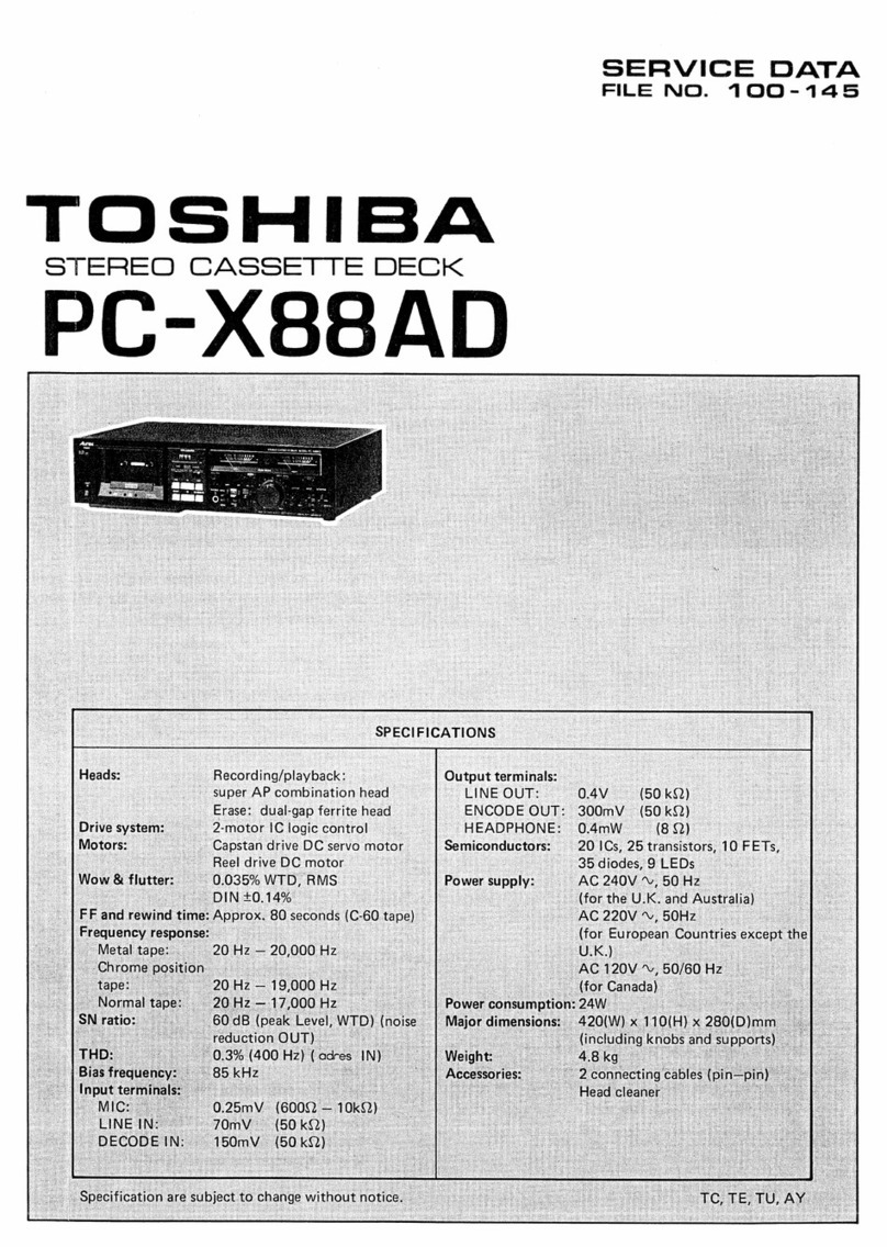
Toshiba PC-E70 User manual

TOSHIBA
STEREO
CASSETTE
DECK
PC-E/0
Tape
Transport:
Mottor:
Wow
&
Flutter:
9
Rewind/fast-forward
Time:
Frequency
Response:
:
“30°°Hz
—
15,000
He
for
Power
Consumption:
~
30:Hz
=
12,500Hz
for
|
|
|
“Record/playback
head:
.
~.0.04%WTD,
RMS
Saas
VOLE
EE
Specifications
=
-|Dolby
NR
Effect:
AP
(super-hard
petmalioy)
pein
Bee
head
x1
Erase
head:
AF
"
gap.
ferrite)
head
x
Lick
:
Dua!
motor.
Ic
legie
contcel
Capstan
drive:
2
DC
servo
motor
x1
Reel
drive:
DC
motor
x1
Output
Level:
-
iPower
Suaoly:
+0.15%(DIN)
Approximately.
70
seconds
»
(C-60)
°°
30°
Hz
17,000.
ie
For
chrome
type
tapes
;
j
~
at
--20
dB:
normal
tapes
at
-20
dB.
|Dimensicns:
__
metal
tapes
at
0dB-
pecifications
are
subject
to
change
without
noti
~ERVICE
DATA
FILE
NO.
100-135
‘5
dB
improvement
at
1
KHz}
10dB
improvement
above
|
»5
KHz
0.6%
at
400
Hz
with
metal
“tape.
°
a
“MIC:
©
0.25mV
(6002
—10KQ)
LINE:
70mV
(50KQ2).
LINE?
0.4V
(SOKO).
os
PHONES:
0.5mW
(8Q)°.
AC
240V
D0
Hz»
(for.
U.K.
‘and
Australia)
AC
220V
~V,
60
Hz
‘(for
=<
European.
Countries.
except
the
U.K.)
~
AC
115/230V.~
50/60
H
Hz’
(for
Middle
East,
Asia
and
South
Amiatice).
Bus
33W
ie
_
420(W).
x
110(H)
x
280(0)
oes
mm
{including
‘k
bs
and
ta
TE,
TU,
AY,
VF

PC-E70
|
CONTENTS
42
{PRARURES.
all
ocx
ae
oe
Lad
Lasoo
shoe
ewe
eens
ead
Tare
oes
1
S..
BLOCK
DIAGRAM:
44.42
uwaidesed
ts
cake
Rene
amen
S24
shies
alah
OL
ahah
Bhs
Ries
©
mati
Sanne
1
3.
OPERATINGCONTROLS............
eRe
ee
ee
Pee
ne
ee
a
ener
eer
2to5
4.-
DISASSEMBICY
INSTRUCTIONS...
6
cindeccannk
aie
leceenews
Saasaen
ee
Lovee
Se
hs
6
to7
x
WADIWST
MENTS
taica
ook
Pe
Seow
tis
bine
rear
anne
se
eee
ee
ete
ie
8
to
9
6.
ELECTRICAL
PARTS
LOCATIONS
.........-
Det
aclo'
eoeawehaseiites
Det
aie
Smet
cigs
Ml
RAPS
coat
10
F<
SCHEMATIC
DIAGRAM
ciel
8
Scena
uierradne
see
oe
Tee
RET
Es
PEM
TSE
eS
11
8
“MECHANICAL
PARTS
LOCATIONS:
..c0.0c¢s..¥abe
ta
eye
Staice
bend
aet
tones
teses
12
6.
“CABINET
PARTS
LOCATIONS
on
s5
Saciewkse
way
dh
tee
testes
eee
pao
Goes
13
SO
(BARE
LIET
acetic
ei
cwhonak
Grnie
oe
edb
len
KA
ae
Be
Pama
Fe
hE
dee
Ee
aM
14
to
19
1.
FEATURES
@
Two-motor
IC
logic
control
system.
METAL
tape
capability
and
super
AP
heads—the
hyperbolic
head
surface
assures
stable
tape
contact
for
all
tape
types.
The
result
is
excellent
recording/play
back
performance.
Newly
developed
pause/mute
function
allows
precise
control
of
non-recorded
spaces
between
recordings.
Tape
transport
control
buttons
light
for
clear
identification
of
mode
even
from
a
distance.
LED
peak
meters.
Auto-repeat
playback.
Timer
recording
and
timer
playback
(timer
optional).
Remote
control
(remote
control
unit
optional).
Dolby*
NR
System.
2.BLOCK
DIAGRAM
LINE
IN
(Lh)
Oey.
ircuit
isoprene
Meter
(L
ch)
LINE
OUT
Record
Wen)
/Playback
Head
{L
ch)
Headphone
AMP.
Record
AMP.
>
—
=
Jack
Record
AMP.
LL
Record
ree
/Playback
5S
i
tee
7b
~P
proyoacs
jaybac!
(R
ch)
AMP.
Headphone
AMP.
77
r
a
=
ze
eae
|
Power
MF
2
Microphone
y
LINE
CUT
|
Seatch
Swit
lrg
Tir
ch)
witc
witcn
'
ee
py
AMP:
se
DOLBY
Timer
230Ve—q
115V
a
Circuit
Seiten
iG
°
a
LINE
IN
Erasure
Ie
et
:
(R
ch)
Y®
Prevention
med
|
”
Switch
ee
|
|
|
}—
|
ahi
wiekces
|
W1§V7230V|
ASO
Detect
yi
pers
|
SOH2z/60H2
vo
!
(
;
Logic
Control
Circuit
é
didd
d
c
>
!
Sa
—
i
———,
TY
as
Remote
Control
|
WY
Jack
Reel
L
ood
Gi)
To
Solenoid
Motor
nila
Power
Switch
-
—
—
-—-——
=
T
Y
Tape
Detect
Capstan
ee
9
E,A
|
Switch
Motor
=
|
LED
Meter
=
(|
<
l
1
aro
S0Hz
|
t
V/
SOHZ
Reguicted
Reguloted
[Se
see
+
Voltage
+B
Voltage
{
Tu
'
Circuit
Circuit
j
re
1
-8
a
240W/50H2
Power
Transformer
Regula’
Voltage
Circuit
a
ee
Figure
1

3.
OPERATING
CONTROLS
:
FRONT
VIEW
COUNTER
RESET
Button
METAL
Indicator
Press
to
zero
the
counter.
DOLBY
Indicator
TAPE
COUNTER
Level
Meters
TIMER
Switch
Show
recording
and
playback
signal
levels.
Sets
the
auto-repeat
playback
mode
and
timer
actuated
recording
and
playback
functions.
(See
page
5
)
Cassette
Compartment
Lamp.
POWER
Switch
ine.
Cassette
EJECT
Button
a
_Only
operates
when
the
tape
transport
is
stopp-
|
‘ed.
f;
oO
©
~
+
i
eee
MIC
(Microphone
jacks)
—
DOLBY*
Noise
Reduction
Selector
PHONES
(Headphones
)
Socket
——
Selg-illuminating
Advanced
Logic
Controls
@
Stop
@
Record
@
Rewind
Figure
2
@
Play
©
Fast
Forward
Wind
©
Pause
Mute
.
BACK
VIEW
Interactive
logic
control
button
(See
page
4)
;
er
Terre!
meee
TT
ee
Sree
ean
Ren
eee
Voltage
Conversion
(VF)
a]
Loosen
two
screws
and
push
the
point
of
the
screw
in
the
arrow
direction,
then
the
voltage
can
be
changed.
TAPE
Type
Selector
RECORD
Level
Control
pescapesens
a,
LINE
IN/REC
Terminals
an
|
t
1
St
|
a
Screw
Up
(230V
>
115V)
Screw
Down
(115V
>
230V)
LINE
OUT/PLAY
a
ee
eee
ae
DO
assser]
Figure
3
*
Noise
Reduction
System
is
manufactured
under
licence
from
Dolby
Laboratories.
“DOLBY”
and
the
Double-D
symbol
are
Trademarks
of
Dolby
Laboratories
Inc.
Figure
4
Figure
5
Remote
Control
Socket


en
Recording
From
Radio,
Disc,
Another
Tape
Unit,
or
TV
(Numbers
refer
to
the
steps
below)
Figure
6
@
Set
the
TIMER
switch
to
OFF.
@
Switch
on
the
POWER.
.
®
Check
that
your
tape
heads
are
clean.
©
Set
up
the
source
that
you
plan
to
record—disc,
radio,
or
tape.
ee
ee
ae
caaiit
3
@®
Insert
a
cassette—with
tab
for
the
side
you
will
record.
©
Set
the
TAPE
selector
to
the
tape
type
used:
NORM,
CrO2,
METAL]
or
FeCr.
The
indicator
will
light
for
metal
tape.
@
set
the
Dolby
NR
selector.
@Dolby
NR
recordings
have
reduced
tape-hiss
on
*”
playback.
:
DOLBY
NR
Dolby
System
off:
if
tapes
are
to
be
played
back
ona
deck
without
Dolby
NR.
Figure
7
or
microphone.
@
Press
the
PAUSE/MUTE
button
to
enter
PAUSE
mode.
@
Press
the
REC
and
PLAY
buttons
simultaneously.
The
PAUSE
and
REC
buttons
will
light.
@
Cue
up
the
cassette
tape:
If
recording
from
the
very
beginning
of
a
cassette
side;
turn
the
RECORD
level
control
completely
anticlockwise,
then
press
the
PAUSE/MUTE
button
momentarily.
The
tape
will
wind
on
past
the
leader,
and
any
previous
recording
will
be
erased.
After
several
seconds
press
the
PAUSE/MUTE
button
again.
@Note:
The
first
few
inches
of
tape
may
be
marked
in
manufacture
and
should
not
be
used
for
hi-fi
recording.
@
Play
the
source
(disc,
radio),
if
possible
at
the
joud-
est
part
of
the
programme,
and
set
the
RECORD
level
control
so
that
the
peaks
of
the
programme
signal
light
the
peak
level
meters
given
on
page
4.
Now,
the
PC-E70
is
ready
to
start
recording.
Cue
up
your
source
(disc,
tape,
etc.).
"os
®
Start
the
source
playing,
then
press
the
PC-E70
PAUSE/MUTE
button
momentarily.
Recording
will
start.
The
PLAY
and
REC
buttons
will
light,
and
the
PAUSE/MUTE
button
light
will
go
off.
8
Dolby
NR
(with
MPX
in!
titer)
to
record
from
FM
OUT,
Lee
stereo
radio
or
MPX
TV,
OFF
;
Dolby
NR
(without
MPX
filter)
to
record
from
disc
PC-E70
@®
Continue
to
observe
the
level
meters.
If
a
very
loud
passage
exceeds
the
correct
peak
levels,
reduce
the
recording
level
gradually
with
the
RECORD
level
control.
An
excessively
high
recording
level
will
cause
audible
distortion
on
playback.
Normally,
the
RECORD
level
control
should
not
be
moved
during
recording.
‘
®
To
stop
recording,
press
either
the
PAUSE/MUTE,
button
momentarily,
or
the
STOP
button.
Alterna-
tively,
the
REW
button
can
be
pressed
immediately
to
rewind
the
tape
ready
for
playback.
Microphone
Recording
(Numbers
refer
to
the
steps
below)
Figure
8
i
The
same
basic
procedure
as
for
recording
from
disc
or
radio
is
followed.
Set
the
TIMER
switch
to
OFF.
Switch
on
the
POWER.
Check
that
your
tape
heads
are
clean.
Insert
a
cassette—with
tab
for
the
side
you
will
record,
Set
the
TAPE
selector
to
the
tape
type
used
(see
“Recording
from
disc,’’
above).
Set
the
Dolby
NR
selector.
Plug
the
microphone(s)
into
the
MIC
jacks
on
the
front
panel.
.
Press
the
PAUSE/MUTE
button
to
enter
PAUSE
mode.
Press
the
REC
and
PLAY
buttons
simultaneously.
The
PAUSE
and
REC
buttons
will
light.
Cue
up
the
cassette
tape
(see
‘Recording
from
disc,”
above).
Position
the
microphones.
If
feedback
(a
whining
noise)
is
produced
from
your
speakers,
turn
down
your
amplifier
volume
control.
While
observing
the
level
meters,
set
the
RECORD
level
control
so
that
the
appropriate
peak
indicators
light
for
a
ioud
passage
of
sound.
Move
the
micro-
phones,
if
necessary,
to
obtain
optimum
and
consist-
ent
recording
leveis.
Leave
the
RECORD
level
control
set
throughout
a
recording
if
possible,
or
adjust
gradually.
@®
To
start
recording,
press
the
PAUSE/MUTE
button
momentarily.
The
PLAY
and
REC
buttons
will
light,
and
the
PAUSE/MUTE
button
will
go
off.
®
Continue
to
observe
the
level
meters
to
ensure
that
the
peaks
do
not
overload
(see
page
4).
@
@6
6
©
©
89
&
6806
PC-E70
@
To
stop
recording,
press
the
PAUSE/MUTE
button
momentarily,
or
the
STOP
button
or
REWIND
button,
depending
on
the
next
operation
required.
Fade-up
Start
A
professional-sounding
fade-up
start
can
be
easily
achieved.
Note
the
exact
position
of
the
RECORD
level
control
in
step
@
,
then
before
step
@
,
set
the
RECORD
level
control
to
zero.
Just
after
pressing
the
PAUSE/MUTE
button
in
step
@
,
smoothly
turn
the
RECORD
level
control
up
to
the
correct
position.
Setting
the
Recording
Level
The
correct
recording
level
depends
considerably
on
the
type
of
tape
used
and
the
program
material
being
recorded.
The
correct
tape
type
and
recording
level
should
be
selected
to
give
the
best
frequency
response
yet
lowest
noise
level.
For
the
following
three
tape
types,
the
RECORD
level
control
should
be
set
so
that
the
peak
level
meters
light
at
the
loudest
passage
of
that
program
selection:
Tape
type
Peak
level
meters
NORMAL
(ferric)
tape
—3
dB
or
0
dB
CHROME
tape
0
dB
or+3
dB
METAL
alloy
tape
+3dBor+5dB
The
high
frequency
response,
in
particular,
depends
considerably
on
the
type
of
tape
and
the
recording
level.
Metal-alloy
tape,
for
instance,
provides
better
high-
frequency
response
than
normal
tape,
thus
giving
much
better
reproduction
of
higher
pitched
instruments
and
voices.
This
is
illustrated
in
Figure
9.
For
the
same
tape,
type
at
lower
recording
levels,
there
is
better
higher-frequency
response
as
shown
in
Figure10.
So,
to
record
program
material
which
contains
consider-
able
high-frequency
sound,
set
the
recording
level
somewhat
lower.
The
level
meter
on
the
PC-E70
is
an
electronic
‘‘digital’’
indicator,
which
displays
the
peaks
of
the
signal,
in
red
over
0
dB
and
in
green
below.
This
allows
very
precise
setting
of
the
recording
level.
The
Dolby
mark
[iQ]
and
the
‘adres’
mark
[AD]
indicate
the
Dolby
an
‘adrescalibration
positions,
respectively.
The
‘adres)
mark
is
for
use
when
the
tape
deck
is
con-
nected
to
an
‘adres’
unit.
The
(adres)
system
is
Toshiba’s
new
noise
reduction
and
dynamic
range
expansion
system.
Metal
tape
Chrome
tape
Level
Normal
tape
High-frequency
Response
(Hz)
Figure
9
Frequency
Response
Curves
for
Different
Types
of
Tape
Recording
level
set
to
+10
dB
Recording
level
set
to
0
dB
Recording
level
set
to
-10
dB
Level
High-frequency
Response
(Hz)
Figure
10
Frequency
Response
Curves
at
Different
Recording
Levels
Mute
Recording
After
recording
a
piece
of
music,
you
may
want
to
create
a
short
silent
space
before
further
recording.
The
advanced—logic
MUTE
feature
of
the
PC-E70
allows
you
to
do
this
easily
and
professionally.
At
the
end
of
a
recording,
tape
transport
is
normally
stopped
by
pressing
the
STOP
button
or
the
PAUSE/-
MUTE
button
momentarily.
If,
however,
the
PAUSE/-
MUTE
button
is
pressed
and
held
in
during
recording,
the
tape
continues
to
run
but
will
be
erased.
When
the
button
is
released
,
the
tape
will
stop
in
record
standby
made
ready
to
continue
recording.
To
start
recording
again
press
the
PAUSE/MUTE
button
a
second
time;
when
the
PAUSE/MUTE
button
is
released
,
recording
will
start.
The
PAUSE/MUTE
button
therefore
serves.a
dual
purpose:
record
mute
and
pause.
For
proper
operation
follow
the
steps
given
in
the
table
just
below:
@
Releasing
the
pause
mode
This
is
illustrated
below.
To
restart
recording,
@®
Making
a
non-recorded
gap
momentarily
press
the
A
non-recorded
gap
can
button
again.
be
created
by
press-
ing
and
hoiding
the
PAUSE/MUTE
button
PAUSEINUTE
during
recording.
When
the
button
is
released,
|
the
tape
stops
in
the
button
operations
|
Pause
mode.
i
no
Hor
,H#o,
oO
SFAe
be
oe)
(a
a
ye
=
=
Zl}
z
=
=
“Pits
AVR
hN
Press
Release
Press
momentarily
Non-record-
iy
Tape
ee
el
adses
|
Ui,
YY
record
mode
Record
mute
_‘
Tape
transport
starts.
stops.
Recording
starts
again.
Figure
711
@When
the
button
is
pressed
during
playback,
only
the
pause
func-
tion
operates.
The
PAUSE/MUTE
button
is
not
effective
in
the
fast-
forward
and
rewind
modes.

PLAYBACK
Normal
Playback
(Numbers
refer
to
the
steps
below)
OO
EET
TOTTORI
ESS
he
i
ei
a
AC
Figure
12
b6
de
@
Set
the
TIMER
switch
to
OFF.
@
Switch
the
POWER
on.
©
Take
up
any
slack
in
the
cassette
to
be
played.
@
insert
the
cassette
with
the
play
side
facing
you.
@
Set
the
TAPE
selector
for
the
tape
type:
NORM,
CrO2,
[METAL],
or
FeCr.
@
Set
the
Dolby
NR
switch
to:
IN
for
tapes
recorded
with
Dolby
NR.
OUT
for
other
tapes.
Note:
The
IN
and
MPX
OFF
positions
give
the
same
operation
in
playback.
@
Press
the
REW
button
to
wind
to
the
beginning
of
the
tape,
or
the
FF
button
to
Fast-Forward
wind
to
a
later
selection.
@
Set
the
volume
control
on
your
amplifier
to
a
reasonable
position,
and
set
the
monitor
(and
tape)
switches
on
your
amplifier
correctly.
@
Press
the
PLAY
button
to
start
playback.
The
PLAY
button
lights.
@
To
gofrom
playback
to
another
mode,
the
PAUSE/-
MUTE,
REW,
FF
or
STOP
buttons
may
be
pressed
directly.
@
At
the
end
of
the
tape,
playback
will
automatically
stop.
Auto-repeat
Playback
The
PC-E70
can
play
a
tape
then
automatically
rewind
to
the
beginining
and
start
playback
again
repeatedly.
Or
it
can
rewind
first,
then
start
auto-repeat
playback.
@
Switch
on
the
POWER.
@
Followsteps
3
to
6
of
Normal
Playback,
above.
©
set
the
TIMER
switch
to
PLAY
REPEAT.
@
(A)
For
Playback—rewind—playback:
Press
the
PLAY
button.
(B)
For
rewind—play—rewind:
Press
the
REW
button.
@®
To
stop
auto-repeat
playback,
press
the
STOP
button.
;
:
Note:
If
the
TIMER
switch
is
left
in
the
PLAY/-
REPEAT
position
when
the
deck
is
switched
off.
Auto-repeat
playback
will
start
auto-
matically
when
the
POWER
is
next
switched
on.
PC-E70
TIMER
RECORDING/PLAYBACK
The
TIMER
switch
should
normally
be
set
to
OFF
before
the
POWER
is
switched
on.
With
the
TIMER
switch
in
the
REC
or
PLAY
positions,
when
power
is
switched
to
the
deck
either
at
the
POWER
switch
or
by
an
external
audio
timer,
recording
or
playback
will
start
automatically.
Note
that
the
audio
timer
must
also
switch
on
and
off
the
power
to
the
otner
hi-fi
compo-
nents.
When
the
end
of
a
tape
is
reached
during
unattended
recording
or
playback,
the
tape
stops
and
the
tape
transport
is
automatically
disengaged.
However,
the
power
to
the
deck
and
your
stereo
system
will
remain
on,
causing
unnecessary
power
consumption
and
pos-
sible
danger.
To
avoid
this,
it
is
advisable
to
use
an
audio
timer
that
automatically
switches
the
power
to
tne
system
both
on
and
off.
Timer
Recording
1
Set
up
the
cassette
deck
and
amplifier,
tuner,
etc.
for
normal
recording:
@
Set
the
TIMER
switch
on
the
PC-E70
to
OFF.
@
Switch
on
the
POWER.
@
Insert
a
cassette
with
a
tab
on
the
side
to
be
recorded.
@
Set
the
TAPE
selector
and
Dolby
NR
selector.
©
Precisely
tune
to
the
desired
radio
station.
@
Preset
the
recording
level,
after
pressing
the
PAUSE/MUTE
then
the
REC
and
PLAY
buttons.
2
Set
the
audio
timer
to
the
desired
recording
start
time,
and
also
set
it
to
switch
off
the
power
to
the
system.
3.
Leave
the
PC-E70
POWER
switch
on.
4
Set
the
TIMER
switch
to
REC.
When
the
time
preset
on
the
audio
timer
is
reached,
the
audio
system
power
will
be
turned
on,
and
automatic
recording
will
start.
Note:
Set
the
TIMER
switch
to
OFF
when
automatic
recording
has
been
completed.
If
the
TIMER
switch
is
accidentally
left
in
the
REC
position,
a
portion
of
a
recorded
tape
may
be
unintentionally
erased
when
the
power
is
switched
on.
Timer
Playback
(for
morning
alarm,
etc.)
1.
Play
the
tape
to
be
used
for
the
morning
alarm
and
adjust
the
amplifier
volume
control
to
a
suitable
volume
level.
2.
Set
the
audio
timer
to
the
desired
alarm
time,
and
also
set
it
to
switch
off
the
power
to
the
system.
3.
Set
the
tape
deck
TIMER
switch
to
the
PLAY
position.
When
the
preset
alarm
time
is
reached,
the
tape
deck
will
automatically
start
playback.
Note:
When
playback
starts
the
PC-E70
will
play
in
the
auto-repeat
mode
until
stopped.
When
the
auto-
repeat
mode
is
no
longer
required,
set
the
TIMER
switch
to
the
OFF
position.
PC-E70
|
4.
DISASSEMBLY
INSTRUCTIONS
2
en
Top
Cover
Removal
.
1.
Remove
four
screws
(A)
and
(B)
from
each
side
of
a
:
Top
Cover
(See
Figure
13
and
14)
2.
Remove
two
screws
(C)
from
rear
panel
of
unit.
(See
Figure
15)
3.
Lifting
the
Top
Cover
upright,
pull
it
back
wards
and
the
Top
Cover
can
be
removed
out.
e
(A)
¢
net!
met
gee
ee
wee
OS
mm
5
anna
Figure
14
Figure
13
Ceca
eeystid
Satie
teh
gh
aha
OH OF
DP
RERE
PAREN
ELSE
IRN
,
Bottom
Cover
Removal
1.
Remove
the
Top
Cover.
:
:
2.
Remove
five
screws
(D)
from
the
bottom
plate.
(See
Figure
16)
2
3.
Remove
two
screws
(E)
from
side
of
the
unit.
(See
:
F
Figure
15
Figure
17)
4.
Bottom
Plate
can
be
removed
from
the
unit.
Figure
16
F
(E)
Figure
17

Cassette
Cover
Removal
1.
Push
the
eject
button
to
open
the
cassette
cover.
2.
Press
the
top
and
bottom
of
cassette
cover
with
fingers,
and
upward
in
direction
of
the
arrow
direc-
tion
(F).
Then
the
Cassette
cover
can
be
removed
from
unit.
(See
Figure
19)
aibidi
(
OO8
Figure
18
Figure
19
TATA
ITIL
WARS
eae
SSR
owt
tl
SE
a
A
eh
ORS
NE
ners
ree
=
Front
Panel
Removal
of
1.
Remove
the
top
and
cassette
cover.
a
2.
Remove
the
three
knobs
(G).
(See
Figur
20)
z
:
3.
Remove
thirteen
screws
(H)
and
(I).
(See
Figure
21
and
22)
*
4.
Front
panel
can
be
removed
from
unit.
®
(H)
g
()
(G)
Figure
21
Mechanism
Assembly
Removal
Figure
22
1.
Remove
cassette
cover.
2.
Remove
six
screws
(J)
and
(K)
(See
Figure
23
and
24)
3.
Remove
the
one
leg(L)from
the
chassis
then
mechanism
assembly
can
be
removed.
g
(J)
(L)
Figure
24

PC-E70
5.
ADJUSTMENTS
S|
R428
TP24R
~
TP24L
Z602_
nase
©]
zao2
R427
|
=)
[Q]
z401
Q419
fe
sit
Figure
25
TEST
EQUIPMENTS
1.
VTVM
(Vacuum
Tube
Voltmeter)
2.
Signal
Generator
3.
Resistance
Attenuator
4.
Screwdriver
RECORD/PLAYBACK
HEAD
ADJUSTMENT
Erase
Head
Adjusting
Screw
Head
Azimuth
Adjusting
Screw
Adjust
for
Maximum
Output.
Figure
26
ERASE
HEAD
HEIGHT
ADJUSTMENT
1.
Temporaily
mount
the
erase
head
so
that
it
will
be
even
by
eye
measurement.
2.
Set
in
PLAY
position
with
setting
a
mirrow
cassette
tape,
MC-09C.
3,
Adjust
the
height
adjusting
screw
so
that
the
upper
edge
of
the
tape
will
touch
at
the
upper
tape
guide
of
the
erase
head.
See
figure
28.
4.
Confirm
whether
the
upper
edge
of
the
tape
is
not
Curled.
5.
Test
Tapes:
MTT-114
(10
kHz)
MTT-150
(400
Hz)
AC-511
(CHROME
TAPE)
Upper
Guide
Figure
27
Touch
Here
Curled
Tape
——
Sith
=
1.
Tape
——
Exon
ae
Figure
28
OK
5.
Paint
the
adjusting
screw
with
lock
paint.
P.S.
When
the
mirror
cassette
is
not
available,
please
re-
model
a
normal
tape,
type
C-90
as
shown
below.
See
figure
29.
Figure
29

t
‘i
’
4
i
3
*
|
PC-E70
PC-E70
|
ADJUSTMENT
PROCEDURES
Description
Nominal
‘Test
Volume
Control
Adjustment
Test
Test
Freq.
|
Specs
Tape
|
REC
|
TAPE
|
DOLBY
Posints
Points
ATT
1
Head
Azimuth
Adjustment
MTT-111
OUT
|
Head
Azimuth
|
LINE
OUT
Adjustment
After
Adjustment
lock
with
screw
point.
Screw
2
’
TApe
Speed
Measurement
00030
Hz|
MTT-111
OUT
Semi-fixed
LINE
OUT
.
resister
in
the
Playback
Sensitivity
580
+
10mV|
MTT-150
OUT
LINE
OUT
Adjustment
Playback
Frequency
Response
MTT-215C
OUT
LINE
OUT
:
SS
Measurement
(Normal)
7
10
Khz
Level
difference
for
315
Hz
Playback
Frequency
Response
4
+2
dB
|MTT-215C
NOR OUT
LINE
OUT
Measurement
(Chrome)
ae
Change
for
10
KHz
Normal
tape
Output
Noise
Level
Under
.
{Blank
Tape
OUT
2.0mV
Line
Input
Level
Adjustment
|
580+
10mV
Adjustment
CrO2
OUT
LINE
OUT
400
Hz
REC.
Volume
adjustment
must
be
kept
—17
dB
till
frequency
response
adjustment
9
Meter
Adjustment
Meter
Indi.
|
CrO2
OUT
R525,
526
LED
Meter
|
400
Hz
—17
dB
Lee
OOD
sol
oo
Pesan
dh
eas
a
Mees
Was
fer
a
ead
he
eke
OPS
oe
cto
ts
GA
Meter
Indi.
CrO2
-|
OUT
LED
Meter
|
400
Hz
—23
|
|
—23
+0.5
dB
Record
Playback
Frequency
O+2
AC-512
LINE
OUT
400
Hz
to
c
Response
Adjustment
—0
Power
Supply
TE:
220V
VF:
230V
TU,
AY:
240V
©
Input:
0
dB=
1V
rms
@
LINE
IN
(Input
Impedance):
600
ohm
@
LINE
OUT
(Load
Impedance):
47
K
ohm
®
Test
Point
Load
Impedance:
No
Load
|
10
kHz
|
—
40
dB
LINE
OUT
400
Hz
—
17
dB
R511
R512
11
Record/Playback
Sensitivity
Adjustment
Measurement
Condition
(Bias
Lead
Adjustment)
TP24L
|
ve
‘
2401
3.
Ae
ene
te)
(
Playback
Sensitivity
Adjustment)
(Line
Input
Adjustment)
R/P
Head
(L)
LINE
IN
‘Test
Tape
(MTT-150)
Resistance
Attenuator
—17dB
Signal
Generator
400Hz
R/P
Head
(R)
SO
°}
Figure
31
VTVM
R415
Figure
30
TP24R
LINE
IN
7
(Rec/Play
Sensitivity
Adjustment)
Resistance
Attenuator
—17dB
400Hz
\
Signal
Generator
LINE
IN
LINE
VTVM
VTVM
LINE
IN
Figure
33
(Rec/Play
Frequency
Response
Adjustment)
7
Generator
Attenuator
4ooHziokrz
49-40
dBV
>
nd
(~)
<b
Ras2
LINE
yt
LINE
IN
=
200K
UT
Figure
34
VTVM
VTVM
Figure
32

PC-E70
PC-E70
6.
ELECTRICAL
PARTS
LOCATIONS
O65!
Emitter
!
2
{3
|
4
5 6
7
a
18
Emitt
Q622
Base
Collector
Q627
Base
— a
9
Q6
mitter
Play
6.46V
pee
Bose.
poecme
£
Yn
0¥
1
2.2V
|
65V
Poy
Rec
2.9v)
[Ploy,Rec
VY]
[Pioy,
Ree
2.0V]
[Rec
S.77V
a
eC
>
ec
oul
PO
ST
TEADPUONE
Ac].—Csi(‘#«STop’
TT
7v}
formers
8.4yl
[omers
@.3v)
[Omers
C8
55Vp0
I
0629
Vornars
35vl
formes
aM
_,
|
HEADPHONE
vACK
Stop
Others
-4y|
[Others
Others
.55V
r
i
\
as
Ti.
1
LiPiay
.
WPigy
eed
mitte;
Collector
_—
1
oy
16.8¥)
Ploy
Pyremie
|
Sew
RS
on
Ne
OT
Ie
i
oe
=
eet
aon
hee
“38Y)
4
Rec
y-_TAMP
RC.Board
\
.a\|
like
TIT
Pe
Otners_-12.7vV
[otners
_
-0.4v
Others
;
;
|
|[stop
18
[Stop
16.1]
/[Pouse
12.7]
T1.25A/250V
(TE)|
;
:
6
71
8
|
iRew,
FF
_-18.0V]/
[Stop
127V
Y
ov
ov
|
inv
"
'
Others
uy
i
/
To
MAIN
P.C.
Board
e
Rec
0.4V
Q414
Gate
[Rec
0.5
Q416
_
Gote
INDICATOR
P.C.
Board
een
ETE
aeeas
joe
}
\
TAPE
x
[tae osc]
RLY
SELECTOR
\
TAPE
OSC
haa:
a
OUT
!
!
!
T
i
1
I
1
i
!
'
1
f
Cm
ie
ase
Bay
38
/
ee
é
~
fotners
BV
e
i
r
°F
ewerag7
cary!
e——o
Lay
file
Gla
Q.
ae,
240i
be
cél2
REI!
owe
Rec
3.9V,
Others
-12.1V)
ASO
P.C.Board
Q419,420
Vette
TF
<
\C9BS
ewe
R502;
_
vet
,
RO
Diag
ON
\
.
:
2°28
cad
Gee
@Alg
Rao
TS
ote
eat
P
R509
Q6I6
Collector
!
ov
|
*
s
Piay,Rec,
FF
be
I.
sine
a
TV
Transformer
£8\
yh
Emitter
|
Fad
penkes
_..
2.8¥
N
s90l
|Pet
eer
a
Power
Switch
Q6IO_
Coilector
@?
iS
1)
g
g
of
+
516
(FY
AR
Q617
Collector
{
[Piay,
Ree
2.9V]
|
Rew
ov!
I
O*here
mac
feck
{
[Play,
Rec
|
{ctnere
)
Base
Piay,Rec
-22V
a3V
Collector
}
See
ig
ho
g
R623
awe
T9OI
Power
Transformer
230V
$902
g
Power
{9
Select
Switch
sg0l
Power
Switch
Q6I4
Base
Pouse
Stop.
Ov
Others
0,65V
Collector
Pause,Stop___3.7V)
[Others
ov}
PL2
Pilot
Lamp
PNK/WHT
LED
Meter
Sil
Leaf
Switch
Q623
Base
Ploy,Rec-7.2V
Q624
Base
sl2
Leaf
Switch
TOSHIBA:
22191775
8
TETO
34a
R
Motor
Collector
Play
1V)
Others
~l2a
Collector
Piay
liv
&
Others
ov
=~10
=
Q7ol,
702
ir
T-8.0v]
lef
-zev]
Ist
ov]
lat
_ov]
-
[S|
ov}
lef
ov]
ov
Ov
ov
S
°
PS
<
<
ov
plas
[ols[=[o[ole
o
siale

PC-E70
PC-E70
7.
SCHEMATIC
DIAGRAM
Q609
Q609
Q606
Q606
Q606
Q6l!
Q6I!
Emitter
Base
Collecter
Emitter
Base
Co
[ree
33V)
Rec
33V
Ploy
2.3V
Pia:
26V
Fioy
7
8V
Pouse
3.7)
(Omers___OV}
Qihers
OV
‘Otners_12.2V)
Rec
2.6
Rec
4.6V
Stop
37
Stop.
otners:
ov
Otners
OV
Otngr
ON)
[Others
0.6y}
_
-—
Indicator
d
|
TIMER
Operating
PC.Board
meta.
voray
|PC.Board
|
a
:
‘actlaphone
=
2
ene
cea
.
REC
/OFF
PLA
TLY205
44%
_.4”risz051
\
n
HEADPHONE
AMP
Jack
ASO
:
3-0
eae
veo
£07
_TLvi08x7
i
pessiossz;
ai
2
f
0630
eae
RC-Boord
|
eg
=
:
a
:
:
oJ
\
S$
NJM4558D-A
Hq
;
[Magnetic
~?
2
$
;
Ji-a
rac
5
628
.
a7
EE
CEN
\
a
RSID
R521
S376
|
8;
Perception
8
y
«8
res
rg
75
ra
:
2eciIS
ca
mea
CoLey_AV
7
|
i
SIS
mi
zecte8
q
na
oy)
oy
,
Sc2i2'
EINE
IN}
|
,
WATT
BTC
238
ig
BCrSot
SoPaot
Bot
sot
i
|
2er2240
|
[Ran
470
[
Ep
seh
TRE
cas
tts
£Fe
/
250970
LcH
:
pra
oe
o
fitters
¢
eee
ots
S
seos,
|
i
7 .
2SC1959
C403
ER
Ox
SRaol7
ast
si
MON
RNS:
Wd
ste
Slew
j
J2-0
33/50
E7
7100
Sn
@
&
(61941)
9-9
©
3
§
A
&
°
oy
o
+
é
-g
05
°
p23
/
JB
(mic)
a
8
j
DIN
Jack
|
Mie
38
8x
,
.
Z ;
.
3
=
3
72
q
C476
33/50
520}
R522
470,
IRGEO!
220
sey
eM,
+8
°
—
a
<
ra)
x
R609
47K
-
+
|
*
2
ak
/
.
a
o42ilo
|
|
*
oe
me
lek
C478
33/16
|
=
9
:
*—
2SK30A-
:
2 i
Bale
470
+
CO
zoe
S750
GR
es
2
ied
f
a
:
5
!
.
oe
ae
Grae
3
al
2
me
|
\
7
.
5
Fi
co
7
1750}
IS
|
i
285
[8
Fa
g
l[utners—
o
|
J2-b
|
|
|
#83
Jn
gS
Ts
(ey)
7
7
=
22Q4I5
&
1a
0423S
2
!
$
hooolr
FT
i
Se
|
um
[
|
882sKS0aGR)
I2SKi3OA-GR
f&
Fe
\oGIe}
|
i
$e
=|
raed
i
©
oa
ce
&
ra
=
:
:
SS
|
z
3 =
z
xs
603
J2SAl0IS-GR
0632
=
vib
see
|
&
py
ols
gy
ege=
Se
—
-TCOIZIP.
wjoor
c}
ae
Z
LINE
IN
ans
8
2
eat
2
‘r@-O-E
>
»
OC,
or
2G
2
g
ey
7
e).
=
:
ad
af
22
22
EEE
2
FE
8
Sx3-~
.
|
|
0407
©
2SC2240-
3%
*
Fae
eo
a
=
=
.
2
‘
Rsk
:
|
|
REGO
/
Reo
Bek
Boe
ese
eto
tS
¢
ome:
:
i
g
33
be
Sb
ae
BY
SB
aE
&
B22]
[e]eTs
|
S{o¢
o
RE7S
WA
Z
(I—O—(5)
OO
”
ele
4
220K
D619
ISISS5V
-
17
=o
Ht
-
3
x
/50-
9.74,
+
Ra7S
t
ay,
28
/2606
,
{38
EC
Sogo8
a
8ST,’
2sa1015-GR
PS
\
2
¢
geeok
oo
cas.
3
270
es
S
9
Se
bz
ES
ea
dt
SS
Hh
arg
10/80
ets
g
+
|IMUTIN
:
R627
4.7K
8
=
of
2SA1020
ig
B~
oe
*
1
gaia
2
3
ont]
STS
tal
307
7
We
pesavare
se
2SC2655
3
38
jo
2SK30A-GR}
S|
(D—G5)
LY—O—O_
|S
2SAI015-GI
10
20M
Fr
‘no|
|
lod
x
lhe
&
ren
Sep
ola
!
4
.
3
Ss]
|
[$3.9
[Ss
3
8
woe
ee
EGO
gn
R646
0619
ac
28
ys
Py
‘OF
jo
len
>
san
m\m
ox
67
z
3
5
S
ee
Oe,
3
ee
&:
3
Sar
es
Nett]
lexS
olf
151555V
1SI585vx3
aeelais
= s
rouse
2M
.
2°
ols
Raat
ges
Play
9.
ave
JO
g
2
7p
Ss
RES
ise
sys
esx
2
8
3
we
l+
z
1
“LS
iS
[2
|fRecono|
fers
ET
gn
21,8ho
Rese
22K
-GR
335
348
aye
SS
[Others
_0.65V
os
S
R437
|
3.3K
i.
Ra58
OAS
S
:
i
ola
ore
08
i
NE646BN-C
ate
Mt
Dictes
Record
5
vt
“
case
3
aca]
a
-
ress
2
aye]
88
Osit
o5i4
TA76IZAP
/Playback
$
7
ae
Sri
-
lgvcase
oe
Bs
:
sore
ores
wssssvlOslt|
ate
Collector
_
Base
owe
yee
Ree
“Saas
$8
(8
49
“
logos
(oS
RE3)
S20
Tote
losc-betm
18
Ress
2SC1959
FY|
Erasure
ae
.
HRPT-77
2
|Q403
Orv
2s'
2
akg
B18
|
2404
axiox
+19
SSAICIS-
oy
ER
9
neae
lw
12
25A950-Y
/
2SC2655-'
27t2w)
«Prevention
Play
Tz
|
®l2sK30a-GRLof?e>
os
siners
S)
[segs
STs:
RePlzaos
See
e
B+
B63
Bead
(oa
B
=
Switch
Fay
$¥e
BACK]|
330P
Q410
go
ov
||R6E84
1K
&
x
we
Bef
E
9{sLesk
3]
S35
a
lala
2SA950-Y,
mere
x18
si
Sia
me
-saq|
|,
318
78
408,
Bar
Se
—
Bsg78
ox
®
95,0610)
\eY
35
nex
los
afew
(be
ss
:
jorners
-o2v|]
18
OVi
|
cag
3/
Rasoseel—-7-
|
|
[OI
peas
arn
©
EXAK43
|
s2-0
@
a
Sus
EPS2SClBly,
Bx?
§
8x32
eT
se
0623
nee!
rg
S.
BFo
:
r
H
BL
Qgo2
a40lg
|
SORELY
220K
feu
Bh
|racen?
Pig}
Tey
$35
|
|
Nb
v
sé
HGR
€s
a5
sere
1K
,
ae
e
fele
;
ee
en
5
Sirgen)
|
2SK30A-
28|C2240,
cae
147/50
gis
a
aed
oimers
61
ov
{
=
isisss|_
|
Q6I5
Q6i9
83
8)
5
-
-
oners
9
3V}1
9
Io
“er
|°
-
es
ro}
ers
DOLBY
AMP.
10424
10M
xg
1S1595V
V1IS3x2SC21|20-Y/2SC2I2/0-lV
of
oY
re
i
©
Reel
,
ee
:
|
ee
_Kaie
=
°
33
¢
“
Q6i2
,
Q613
£53
rea2
33K
OOM
Shon
&
7)
5
Ch)
:
ae
=Ot7s
6,
gaan
*™
3}
Say
as
7
SAIOIS
2Sc18i5
ab
is
“fe
ers”
=|
|reve
|
STs
«
Mote
2
5
te
o
gms
SN
3
m
lov}
om
S&
SSKSCAG
RI
Wy
2
;
=e
$
r
:
lee
|
AS
=e
fae
:
;
:
“GR
30%
\-GR
$35
og
Bedhe
Rec
250]
g
{7}
)
1s
fetep
rea,
S
[Ree
Orv]
82
"
3.
Sy!
3
icral
H
;
5
88
\e
2
8
$e
mo
oTs
Pry
29v|
%
no
|
3
|
Lon
formers
11
VJ
‘Omens
OV]
°
28
|
$Raz2]
Box)
ES
ESV}
|e
i
x
§
glols
Rew
ov]
8
ge
[8T8
t>}
Q618
2
S|
a7K
z7o|
8x
Si
RA70
10M
|
8
Pa
=
fomers__7.3v]
©
8
1S
Sienogrllector
4
1)
R664
1K
:
.
88
3
82
a"
aa3e
Rad2]
oO
8
|
&
i
:
3
4
a
OK
go
LIMOTOR
TURNOVER
7
<eon
g
a3
j
bie
5
ig
Fe
38
aw
Tet
§
Rx
z
i
a
%
cate
S
G
teres
eee
ew
oT]
=
622
AN
o
.
Ree
oy
©
fay
=
afa22
Olt
gS
Bx
ax
Et
St
&]
330
®
ee
thers
OW
2SA1020-Y
Lamp
=
[Pioy
OV
0404/2
>
@
F005,
wae
Sag
Ee
Box
BES
©
|
caso
o
>
x
3
=
alle
PL2
lee
ov
:
=
Sy
mB]
FBnse
gone
Be
B81
Leslee
Bee
7"
33/80
I)
8
:
S$
el
ale
Bb
|e
3x
Cossettelonen
—73¥
:
2
.
ES
t
o
ad
2
eS
=
ia
ee
GR
ma
nasa
on
°T
[Sc]
88
$8
*
Joes!
Y18
Led
Fo el
#8
sts
9:
g
"Ty?
;
TAT3I8P-2
ea)
or
3
Re44
2K
pov
49)
47K
°S
Ta731IEP-2|
$TP\
Tse
|e
e
Wet
eS
Cu
Moin
:
eo it
beo0
38
3]?
p
C424
RGSS
18K
Si-d
3
i
laid
es
ke
%
Ay
yi
Got
lector
2
°
25
%
Gn
eae
y
624
3
An
siz
[Ploy
20]
2%
2602
sean
38
cH
“9428
=
>
.
62:
ee
2SAl015-GR
[SIF
S
S
ISIS
aul
Motor
Switch
j
[Rec
20V
:
4
38
es
dae
[seesx
7?
Sy
Pee
__gt
S41
I
Scigis-
crs
"
Séiais-cr
Hs
2
8
eh
ee
Omerte3v
eanee:
:
eo)
8S
;
C465
0.15/50
!
a
E2%
$22
Q408
410
=
wbx
Q70!
g
sex
REST
10x
Rez!
A
mn
My
;
Ay
Powe
ie
El
Bence
=
i
:
*Q404
@
2SA970-BL
2S8C2240-
'501
[1001
Tow)
TAT6IZAP
2
3
TA76IZAP
BS
&3e8
a.
BRN
Switch
2
1
:
2SK30A|
ge
3
BL
‘
8
‘
629
&
et
Oe
mA
BS
ik
062
u.
|
“OR)
384
428
GAS
OSC)
widS28on-ah*?
=
mo
ltt)
|
al
Ts
a]
[s
ge
aak
pce
Pacesse)
8
te
[leh
a
a
2602
osc
=04V]
Sth
oR
|
fat
ov
:
is
EN
als
=
at
sel|
|;
Boat
Rie
|
Be
Be
(Bs
eee
LTS]
Th
|
mie
Erase
se
S
Rec
733]
12-4
88
4]
-i25v
el L&
rst
ef
fe
rs
{e]
3
eel
|
(EE
a
Head
rar
x
Weae
foox
sf
ov
2X)
XO)
KO
COOKE
|
2SCIIRRY
os02
2SCNRAVESF
wsesev,
$22
|
fe
—eseu
Q
18
+
Se
ya]
|
ete
H
°
|
Tomers2.55V7
5
=
Q626
RECORD
AMP]
|
foi"
015/50
=.
7!
Ov.
T
SV]
(25v)
zy
:
33
3
2SAl0ls
3
£3
rs
Ro
sf
i25v
+
|
he
HET-52
oT
t
rege
“CR
©
BRT
no
EMOTES
|e
&
"23
Q627
aa
18K
3
(IAI
OKSK
YS
aX3)
©)
OOK
POS
a2)
2
fe
H
-)
f-)
clo
°
als
2SCIBI5-GR
Bs
——
92
a]7K
|
Si-e
=
0426
Lamp
|8&
s[atgrstelsls|s[Sls|s8
SSIS
sl
sisisielsisiol)
|
t
|
38
Power
rate
Sit
¥
=
Je!)
9x5
Others
OV.
bene
ges
28CI8IS|
|PC
Board
f
EeNSEsesusesey
BoasAsnsesesasasnsesns.9S
og
AGH
Sitch
|
|
Collector
Py
g
be
°.
sTo2
-cR
-
ge
:
iC
Rts
herr
RYIRIRIRIRPRIRIRTRIRYRIRIR
T
BLU
witc!
Plo;
€1V
i
bs
a
gs
EBS
oe
egress
tee
[8]3
-S
FEES
LEleelelelelelele
CIELSIEIEIEIEIEIELEIELE)e
:
|
oly
sist
88/788
|
gas
8
Ree
O2V
se]
*]°
[88
al
Us
!
S
2
ge
Others
OV
@
si
:
ashe
aay
zee
Hy
BES
ES
$85
3
of
tt
[POWER
“SUPPLY
|
F
7
i
sia
YY
be
mei
2
‘
-
14V/7OmMa
.
Rec
=i0.0v]
[Re
=On1V)
‘
4
‘
|
omens]
[omens
26
Lied
So
OTOH!
Saag
Meter
P.C.Boord
Main
P
C.
Board
7
\
H
1
ety!
ot
cs
A
fee
aos
Al
E
+
ee
ee
:
xe
ait
S1
Remote
Switch(
Tope
Selector)------
-----NORMAL
Position,
4)
S4~S9
Key
Switch
(Operating
Mechanism)
----OFF
Position.
Record
Signal
Path
(Lch).
aX
aie
ene
Dolbw)aciietes
edepe
awed
iti
i
+
-OFF
Position,
)
......5
Microphone
,
Headphone
Pt
O.1V)
[Pia:
omvy|
)
S2_
Rotary
Switch(
Dolby)
OFF
Position.
5)
Stl
Leaf
Switch
(Erasure
Prevention)
i
GRE
Bod
f
4
rT
Piay
0
3
$3
Side.
Switeh
Timer)-
viele
cesses
sss
-OFF
Position,
6)
si2
Leaf
Switch
(
Motor)
-
+++
++
OFF
Position.
Signat
Path
(Lch).
[Rec
ov]
TU,AY}!
Ao
=
7)
$901
Push
Switch(Power)}---
9
+77
>>
+
-OFF
Position./
gazes
Playback
Signal
Path
(Rch),
.
Rec
63v)
[Ree
ov]
[1
T2713
Ta
CE
HB
EE
ST
-
T
Collector
Bose
|
Others
__3.5V
Others
4.1V.
——
[-82V,-LiVv,
OV
~60V,
-78V.
OV.
OV
Ov
ov.
ov
04v
Others
OV,
sé
76
@
fo
ti
es
sis
Q6i0
Fiay
17
3v]
Q608
Q608
=8.0V]
OV
|
-1.0V
|
-6.2v
ov
|
Ov
Ov,
ov
Ov
|
19V
(-57
B.0V
ae
B
|
|
Bose
Collector
a
3
|
0701,702
ence
See
|
|
as.
#
|
|
[FF.Rew
-i8
OV]
-18.0V.
:
[Px
iiv)
ei
0
‘
x
O63
Q613
[sa
Collector
Bore
|
$a0p
1157230V
|
\
(wen
A
(ay
(_)
50/60Hz
|
.
|
eating
—~
a
J
CAUTION:
The
/\
mark,
the
symbol!
No.
circled
with
rectangle
in
the
schematic
diagram
and
the
shaded
area
in
the
Parts
list
designate
components
which
have
special
characteristics
important
for
safety
and
should
be
replaced
only
with
types
identical
to
those
in
the
original
circuit
or
Ww
specified
in
the
parts
list.

|
PC-E70
PC-E70
|
8.
MECHANICAL
PARTS
LOCATIONS
|
9.
CABINET
PARTS
LOCATIONS
Mecha
P.C.B.
Bei
1
Note:
The
parts
without
Key
No.
on
this
exploded
Note:
The
parts
without
Key
No.
on
this
exploded
Parts
list
are
unserviceable
parts.
parts
list
are
unserviceable
parts.
-12-
ee
—13-

10.
PARTS
LIST
CAUTION:
The
/\
mark,
the
symbol
No.
circled
with
rectangle
in
the
schematic
diagram
and
the
shaded
area
in
the
parts
list
designate
components
which
have
special
characteristics
important
for
safety
and
should
be
replaced
only
with
types
identical
to
those
in
the
original
circuit
or
specified
in
the
parts
list.
Symbol
No.
Part
No.
Description
Symbol
No.
Part
No.
Description
CABINET
PARTS
18
22707451
|
Screw,
BID
¢2
x
5mm
19
22707505!
Screw,
BID
¢2
x
6mm
25819459
|
Front
Panel
Ass’y
20
22703118|
E
Washer
$2
25817809
|
Cover
Ass’Y,
Cassette
1
22703279!
E
Washer
$3
22841229")
‘Top
Gover
22
|
22217357]
Head,
Record/Playback
HRPT-77
25817829
|
Cover
Ass’y,
Mechanism
23
22218213|
Head,
Erase
HET-43
305
25838522
|
Jack
Plate
(TE)
24
25726489
|
Sleeve,
Erase
Head
25838523
|
Jack
Plate
(TU,
AY)
25
25753325
|
Roller
25838533
|
Jack
Plate
(VF)
26
25753347
Roller-H
306
22828048
|
Leg
27
25753348)
Roller-HL
308
25771412
Spring,
Cassette
UP
28
25764400!
Washer,
3
309
25814361
|
Decoration
Ass’y
30
25771951)
Spring
310
|
25873224
|
Counter
31
25772240
|
Spring,
Head
311
25837494
|
Knob,
DOLBY
NR/TAPE
32
25772438
|
Spring,
Erase
Head
SELECTOR
33
25773469
|
Spring,
Pressure
Lever
312
25837469
|
Knob,
Rec-R
34
25717473)
Pressure
Roller
313
25837468
|
Knob,
Rec-L
35
25791213)
Chassis
Ass’y,
Head
314
22884010
|
Knob,
Power
36
22707494
|
Screw,
DTBID
$2.6
x
4mm
315
25837467
|
Knob,
Counter
37
25764549
|
Washer,
$1.7
316
25837475
|
Knob,
Timer
38
25766019
|
Washer,
Back
Tension
317
25838448
|
Knob,
Mechanism
39
25771586
|
Spring
319
25817828
|
Holder
Ass’y,
Cassette
40
25772254
|
Spring,
Back
Tension
|
324
25845528
|
Bush,
Cord
41
25712360
|
Reel
Drum
Ass’y
329
25838444
|
Dial
Plate,
Meter
42
25764570
|
Washer,
$2.1
331
22707522
|
Screw,
3
x
6mm,
Chrome
43
25791191]
Reel
Mount
Ass’y
332
22705022
|
Rivet,
Plastic,
36x
5.5mm
45
25735246
|
Retainer,
Spring
333
22707521
|
Screw,
FLDT
03
x
6mm,
BLK
46
25735252
|
Washer,
Stopper
334
22707350
|
Screw,
DTBID
62.6
x
5mm
47
25762401
|
Felt,
FF
335
22707397
|
Screw,
DTBID
42.6
x
5mm,
BLK
48
25772572
|
Soring,
Idler,
£F
336
22707445
|
Screw,
DTBID
93
x
6mm
49
26713972|
idigp
Assis
FE
337
22707446
|
Screw,
DTBID
$3
x
6mm,
BLK
50
25791141
|
Plate
B
Ass’y,
Idler
338
22701326
|
Screw,
Tapping
¢3
x
8mm,
BLK
51
22701389
|
Screw,
BID
2.6
x
3mm
341
22707626
|
Screw,
FLT
02.6
x
8mm,
BLK
52
|
25791216
Motor
Assy,
Reei
342
22707366
|
Screw,
DTBID
$2.6
6mm
53
25791297
|
Motor
Ass’y,
Main
344
22707301
|
Screw,
Tapping
2.6
x
8mm
54
22707429
|
Screw,
Motor
345
22707165
|
Screw,
36x10
mm,BID
BLK
(VF)
56
25755448
|
Belt,
Main
346
22950753
|
Label,
Voltage
(VF)
57
25761238
|
Cushion,
Motor
347
22703203
|
Washer,
3¢
(VF)
59
25764398
|
Washer
$2.5
alee
61
|
25783219
|
Screw,
THRUST,
Flywhee
MECHANISM
62
25717451
|
Flywheel
Ass’y
1
22707350
|
Screw,
DTBID
62.6
x
5mm
63
25718158
|
Holder
Ass’v,
Capstan
2
22707169
|
Screw,
BID
$2.6
x
10mm
64
22707452
|
Screw,
BID
¢3
x
6mm
3
22707617
|
Screw,
DTPAN
$2.6
x
6mm
-
68
22701472
|
Screw,
FLT
5
25755351
|
Belt,
Counter
73
25771630
|
Spring
8
25724420
|
Bush
25776180
|
Spring
9
25761400
|
Stopper,
Head
Chassis
22703269
|
Washer
63
11
25783222
|
Guide-AL
25791074
|
Damper
Ass‘y
12
25783223
|
Guide-AR
25771898
|
Spring
25762384
|
Feit,
Frictione
—~14—

PC-E70
|
Q401,
402
403,
404
411,412
413,
414
415,416
417,
418
421,422
423,
424
0405,
406
0407,
408
Q409,
410
0419,
420
0425,
426
Q601,
602
604,
605
610,
613
614,
620
625,
627
Q603,
606
607,
608
609,
612
624,
626
0611
0615,
619
0616,
617
0618,
623
Q621
Q622
0628,
629
630
0631
Q632
Q701,
702
;
0901,
902
|
Q903
D401,
402
403,
404
405,
406
407,408
608,
609
610,
611
612,613
|
614,
615
616,
617
618,
619
620,
621
|
06071,
602
|
Symbol
No.
|
Part
No.
TRANSISTORS,
ICS
&
DIODES
22114681
22114470
Transistor,
2SK30A-GR
Transistor,
2SC2240-GR
Transistor,
2SA970-BL
Transistor,
2SC2240-BL
IC,
NE646BN-C
Transistor,
2SC1815-GR
Transistor,
2SC1815-GR
Transistor,
2A1015-GR
Transistor,
2SC982TM
Transistor,
2SC2120-Y
Transistor,
2SA950-Y
Transistor,
2SC2655-Y
Transistor,
25C1959-Y
Transistor,
25A1020-Y
IC,
NJM4558D-A
IC,
TA7318P-2
,
IC,
TC97127P
IC,
TA7612AP
Transistor,
25C1173-Y
|
Transistor,
2SA473-Y
Diode,
1S1553V
|
Diode,
1$1555V
Symbol!
No.
Part.
No.
Description
+
D622,
623
624,
627
629,
630
631,
634
635
D603
D604
D605
D606,
607
D625
D626
D628
D632
D633
D701
zi
Diode,
1$1555V
Diode,
TLO108,
LED
Diode,
TLR124,
LED
Diode,
TLG
124A,
LED
Diode,
TLY108,
LED
Termister,
D33A
Diode,
02Z6.8A
Diode,
$5277B
Diode,
TLG205,
LED
Diode,
TLY205,
LED
Diode,
$4424,
LED
Meter
A\|
D901
|
Diode,
1B2Z1
ZA\|
D902
ve
Diode,
1B2C1
A\|
D903
22115485
|
Diode,
WLO2M
D904,
905
Diode,
05213L
D906
Diode,
05Z10-U
D907,
908
Diode,
1$1553V
LS
|
ELECTRICAL
PARTS
Alu
22147224
|
Coil,
Solenoid
|
L401,
402
|!
22232207
|
Coil,
2.2mH
A\j
T9017
_
|
22223866
Transformer,
Power
(7
E)"
AN
22223867
|
Transformer,
Power
(TU,
AY)
A
-.
|
22223868
|
Transformer,
Power
(V
F)
$1
22195553
|
Switch,
Slide,
Tape
Silector
$2
22195624
|
Switch,
Rotary,
Dolby
$3
22195566
|
Switch,
Slide
Timer
$49
22195623
|
Switch,
Key,
Mechanirm
S10
22195626
|
Remote
Wire
4P,
(S1}
1$714
22195199
|
Switch,
Leaf
Erasure
'revention
$12
22195603
|
Switch,
Leaf,
Motor
A\|s901
22195686
|
Switch,
Power
A\|
s902
22146186
|
Switch,
Voltage
Selecor
(VF)
J
_
|
22163759
|
Jack,
US-4P
iid
J2
22163675
|
Jack,
6.5¢-2P
Micropto
ne
22167893
22163777
—~15—
Socket,
DIN-7P
Jack,
66
Headphone

Symbol
No.
|
Part.
No.
2401,402
|
22153116
405,
406
2403,
404
2601
Z602
PL1
22153117
22120053
22132530
22113508
_|
22113509
(22144357.
122144408
|
“|
22176286
|
|
22176536:
|
22176125
929176588
“122165078
Description
PC-E70
Description
Filter,
DOLBY
BL
Filter,
DOLBY
BK
MPE,
DM101A
Bias
Oscillator
Unit
Lamp,
14V,
70mA
Meter
Plate
Lamp,
12V
40mA
Mechanism
_
Fuse,
,
71.25A/250V
(TE,
TU,
AY)
Fuse,
T500mA/250V(TE,TU,
AY)
‘Cord,
Power,
E2ES
(TE)
1
Cord;
Power,
‘BS
(TU):
Cord,
Power,
EP
(VF).
”
Cord,
Power,
“‘A2SA-7A
(AY).
:
‘Holder,
Fuse,
4P
(TE,
TU,
AY)
©
CAPACITORS
D
=
+0.5
pF,
J=
+5%,
K=
CD
=
Ceramic
Disk,
EL=
Electrolytic
ABBRVIATIONS:
+10%,
M=+20%,
Z
=
—20
+80%
MY
=
Mylar,
PS
=
Polystyrene
BL
=
Barrier
Layer
22349102
|
22488339
22488339
22361509
22362180
22349151
22349331
22362180
|
22488479
|
22483101
22371153
22349331
22483470
22483101
C401,
402
C403,
404
C405,
406
|
C407,
408
C409,
410
C411,412
C413,414
C415.416
C417,418
C419,
420
C421,422
C423,
424
C425,
426
|
C427,428
;
EL,
100mfd,
10V
C429,
430
C431,
432
C433,
434
C435,
436
C437,
438
C439,
440
22483101
|
22349151
22349151
22488100
22371472
22371562
22371273
22349331
22371472
C441,
442
C443,
444
C445,
446
CD,
1000
pF,
50V
K
EL,
3.3mfd,
50V
EL,
3.3mfd,
50V
CD.
5pF,
50V,
D
CD,
18pF,
50V,
K
CD,
150pF,
50V,
K
CD,
330pF,
S0V,
K
CD,
18pF,
50V,
K
EL,
4.7mfd,
50V
EL,
100mfd,
10V
MY,
0.015mfd,
50V,
J
CD,
330pF,
50V,
K
EL,
47mfd,
10V
EL,
100mfd,
10V
CD,
150pF,
50V,
K
CD,
150pF,
50V,
K
EL,
10mfd,
50V
MY,
4700pF,
50V,
J
MY,
5600pF,
50V,
J
MY,
0.027mfd,
50V,
J
CD,
330pF,
50V
K
MY,
4700pF,
50V,
K
Symbol
No.|
Part.
No.
an
c449,
450
|
22480006
C451,
452
|
22480003
C458,
454
|
22488100
C455,
456
|
22372473
C457,
458
|
22483221
C459,
460
|
22349102
C461,
462
|
22488479
C463,
464
|
22488479
C465,
466
|
22480004
C467,
468
|
22360330
C469,
470
|
22360327
C471,472
|
22360328
C473,
474
|
22371223
C475,
476
|
22488339
C477,
478
|
22485330
C479,
480
|
22488339
C481,
482
|
22349332
C483,
484
|
22488339
C485,
486
|
22488100
C601
22485220
C602
22485330
C603
22485101
C604
22483101
C605
22488100
C606
22488109
C607
22488109
C608
22349102
C609
22349102
C610
22349102
C612
22342103
C613
22485220
C614
|
22488100
C615
22488339
C616
|
22360484
C618
|
22483101
C619
|
22488229
C620
22360484
C621
22488339
C622
22483101
C623
22485330
C624
22488479
C625
|
22486101
|
C626
22488100
C627
'
22483101
C628
22342103
C629
22488109
C630
|
22485330
C631
22485101
C632
22380101
C635
22485330
C636
22488109
EL,
100mfd,
10V
/
EL,
100mfd,
10V
EL,
220mfd,
10V
EL,
0.33mfd,
50V
EL,
0.1mfd,
50V
EL,
10mfd,
50V
MY,
0.047mfd,
50V,
K
EL,
220mfd,
10V
CD,
1000pF,
50V,
2
EL,
4.7mfd,
50V
EL,
4.7mfd,
50V
EL,
0.15mfd,
50V
BL,
0.033mfd,
25V,M
BL,
0.01mfd,
25V,M
BL,
0.015mfd,
50V,
M
MY,
0.022mfd,
50V,
J
EL,
3.3
mfd,
50V
EL,
33mfd,
16V
EL,
3.3mfd,
50V
CD,
3300pF,
50V,
K
EL,
3.3mfd,
50V
EL,
10mfd,
50V
EL,
22mfd,
16V
EL,
33mfd,
16V
EL,
100mfd,
16V
EL,
100mfd,
10V
EL,
10mfd,
50V
EL,
imfd,
50V
EL,
1mfd,
50V
CD,
1000pF,
50V,
Z
CD,
1000pF,
50V,
Z
CD,
1000pF,
50V,
Z
CD,
0.01mfd,
50V,
Z
EL,
22mfd,
16V
EL,
10mfd,
50V
EL,
3.3mfd,
50V
CD,
0.047mfd,
50V,
Z
EL,
2.2mid,
50V
CD,
0.047mfd,
50V,
Z
EL,
3.3mfd,
50V
|
EL,
100mfd,
10V
EL,
33mfd,
16V
EL,
4.7mfd,
50V
EL,
100mtd,
25V
EL,
10mfd,
50V
CD,
0.0imfd,
50V,
Z
EL,
Imfd,
50V
EL,
33mfd,
16V
EL,
100mfd,
16V
PS,
3900pF,
200V,
K
EL,
33mfd,
16V
EL,
Imfd,
50V
21h

PC-E70
Part.
No.
[
Description
22488100
JEL,
10mfd,
50V
22485330
JEL,
33mfd,
16V
22349221
|CD,
220pF,
50V
,
K
22485330
|EL,
33mfd,
16V
22485330
JEL,
33mfd,
16V
22483331
|EL,
330mfd,
10V
~/f22340147
|CD,
0.01mtd,
400V.
-
122486222
|EL,
2200mfd,
25V_
2
[92486102
|EL,
1000mfd,
25V.
22485221
|EL,
220mfd,
16V
22485471
|EL,
470mfd,
16V
“199486102
[EL
1000mfd,
25V.
22485221
|EL,220mfd,
16V
-
22485471
|EL,
470mfd,
16V
22485221
|EL,
220mfd,
16V
22485471
|EL,
470mfd,
16V
22488479
|EL,
4.7mfd,
50V
RESISTORS
All
resistors
are
carbon
film
%W,
£5%,
unless
otherwise
noted.
K
=
1000.
M
=
1000000
es
R401,
402
|
22545333
|33K
ohm
'R403,
404
|
22555104
|
100K
ohm
R405,
406
|
22555222
|
2.2K
ohm
|R407,408
|
22555104
|
100K
ohm
R409,410
|
22545102}
1K
ohm
R411,
412
|
22545471
|
470
ohm
R413,414
|22555473
|47K
ohm
R415
22655425
|
50K
ohm,
A,
Variable,
Rec
Levei
R417,418
|22555104
|
100K
ohm
R419,420
|
22555473
|47K
ohm
R421,422
|
22545472
|4.7K
ohm
R423,
424
|
22555104
|
100K
ohm
R425,
426
|
22545154
|
150K
ohm
R427,428
|
22658501
|
500
ohm,
Semi-fixed
Variable
R429,
430
|
22555224
|
220K
ohm
|R431,432
|
22555682
|
6.8K
ohm
(R433,
434
|
22555470
|47
ohm
R435,
436
|
22555222
|
2.2K
ohm
R437,
438
|
22555392
|
3.9K
ohm
R441,
442
|
22555332
|
3.3K
ohm
R443,
444
|
22555123
|
12K
ohm
R445,
446
|
22545106
|
10M
ohm
E447,448
|
22545392
|
3.9K
ohm
R449,
450
|
22545392
|
3.9K
ohm
Symbol
No.
|
Part.
No.
Description
R451,
452
R453,
454
R455,
456
R457,
458
R459,
460
R461,
462
R463,
464
R465,
466
R467,
468
R469,
470
R471,
472
R473,
474
R475,
476
R477,478
R479,
480
R481,
482
R483,
484
R485,
486
R487,
488
R489,
490
R491,
492
R493,
494
R495,
496
R497,
498
R499,
500
R501,
502
R503,
504
R505,
506
R507,
508
R509,
510
R511,
512
R513,
514
|R515,
516
R517,
518
R519,
520
R521,
522
R523,
524
R525,
526
R527,
528
R529,
530
R531,
532
1R6OQ1
R602
R603
R604
R605
R606
R607
R608
a7
22545106
22545106
22555102
22555104
22555473
22555332
22555105
22555101
22545106
22545271
22555274
22555224
22545271
22555103
22545106
22555103
22545106
22555123
22545183
22545473
22545273
22555272
22555103
22555472
22555104
22555470
22545471
22555222
22555472
22658464
22545102
|
22555104
22555332
22555123
22545471
22545471
22658464
22555103
22555152
22555103
22545221
22555562
22555224
22545103
22545472
22555333
22545472
22545333
|
a
22658470
200K
ohm,
B,
Semi-fixed
Variable
10M
ohm
10M
ohm
1K
ohm
100K
ohm
47K
ohm
3.3K
ohm
1M
ohm
100
ohm
10M
ohm
270
ohm
270K
ohm
220K
ohm
270
ohm
10K
ohm
10M
ohm
10K
ohm
10M
ohm
12K
ohm
18K
ohm
47K
ohm
27K
ohm
2.7K
ohm
10K
ohm
4.7K
ohm
oy
100K
ohm
47
ohm
470
ohm
2.2K
ohm
4.7K
ohm
50K
ohm,
Semi-fixid
Variable
1K
ohm
100K
ohm
3.3K
ohm
12K
ohm
470
ohm
470
ohm
50K
ohm,
Semi-fixecdt
Variable
10K
ohm
1.5K
ohm
10K
ohm
220
ohm
5.6K
ohm
220K
ohm
33K
ohm
10K
ohm
4.7K
ohm
33K
ohm
4.7K
ohm

Symbol
No.|
Part
No.
R609
22545473
22555683
22555223
22555103
22555104
22555222
22555103
22555104
22555103
22555222
22555103
22545154
R621
22545473
R622
22555333
R623
22555104
R624
22555333
R625
22555104
R626
22555472
R627
22555472
R628
22555153
R629
22555103
R630
22555104
R631
22555223
R632
22555222
R633
22555473
R634
22555333
R635
22545472
R636
22555222
R637
22555104
R638
22545333
R639
22555333
R640
22555104
R641
22555472
R642
22555333
R643
22555104
|
R644
22545472
R645
22555473
|
R646
22555473
R647
22555101
R648
22555121
R649
22545121
R650
22555121
R651
22545121
R652
22545121
R653
22545223
R654
22555104
|
RGSS
22570300
R656
22555391
R657
22555470
R658
22658491
R659
22555122
R66O
22555102
R661
22555102
22545332
Description
47K
ohm
68K
ohm
22K
ohm
10K
ohm
100K
ohm
2.2K
ohm
10K
ohm
100K
ohm
10K
ohm
2.2K
ohm
10K
ohm
150K
ohm
47K
ohm
33K
ohm
100K
ohm
33K
ohm
100K
ohm
4.7K
ohm
4.7K
ohm
15K
ohm
10K
ohm
100K
ohm
22K
ohm
2.2K
ohm
47K
ohm
33K
ohm
4.7K
ohm
2.2K
ohm
100K
ohm
33K
ohm
33K
ohm
100K
ohm
4.7K
ohm
33K
ohm
100K
ohm
4.7K
ohm
47K
ohm
47K
ohm
100
ohm
120
ohm
120
ohm
120
ohm
120
ohm
120
ohm
22K
ohm
100K
ohm
27
ohm,
2W,
Metal
film
390
ohm
|
47
ohm
300
ohm,
Semi-fixed
Variable
1.2K
ohm
1K
ohm
1K
ohm
3.3K
ohm
R665
R666
R667
R668
R669
R671
R672
R673
R674
R675
R677
R678
R679
R680
R681
R682
R683
R684
R685
R686
R687
R688
R689
R690
R691
R692
R693
R694
R695
R696
R697
R698
R699
R701,
702
R703,
704
R705,
706
R707,
708
R709,
710
711,712
713,714
715,
716
717,718
719,
720
721,722
723,
724
R725,
726
727,
728
729,
730
731,
732
Symbol
No.
R676
Part
No.
22555103
22545102
22555103
22555103
22555103
22555103
22545223
22545102
22545103
22555102
(22555102
22545560
22555105
22555224
22555224
22545102
22555154
22555224
22555102
22555473
22555224
22555223
22545472
22545223
22555333
22555103
22555103
22555104
22547331
22547391
22570305
22545472
22555104
|
22555224
22555104
22555273
22555103
22555681
22555821
22555681
22545102]
Description
10K
ohm
1K
ohm
10K
ohm
10K
ohm
10K
ohm
10K
ohm
22K
ohm
1K
ohm
10K
ohm
|
22570847|
10
ohn
220K
ohm
220K
ohm
1K
ohm
150K
ohm
220K
ohm
1K
ohm
47K
ohm
220K
ohm
22K
ohm
4.7K
ohm
22K
ohm
33K
ohm
10K
ohm
10K
ohm
100K
ohm
330
ohm,
%W
390
ohm,
2W
68
ohm,
2W,
Metai
Oxided
titm
4.7K
ohm
100K
ohm
220K
ohm
100K
ohm
27K
ohm
10K
ohm
680
ohm
820
ohm
680
ohm
|
PC-E70
—~18—

Symbol
No.|
Part
No.
Description
R733,
734
|
22555821
22547331
22545560
22547471
22555560
22547181
22555560
22555102
820
ohm
330
ohm,
%W
56
ohm
330
ohm,
ZW
56
ohm
180
ohm,
“%W
56
ohm
1K
ohm
ACCESSORIES
22164775
|
Cord,
Joint
22164314
|
Plug,
AC
Adapter
(VF)
22990756
|
Clener,
Head
22902792
|
Owner's
Manual
(TE,
TU,
AY)
22902811
|
Owner’s
Manual
(VF)
;
TOSHIBA
CORPORATION
2-1,
GINZA
S5S-CHOME,
CHUO-KU,
TOKYO
104,
JAPAN
PRINTED
IN
JAPAN
July
21955919
1980(¢
Table of contents
Other Toshiba Cassette Player manuals

Toshiba
Toshiba RT-S933 User manual

Toshiba
Toshiba RT-200S Mounting instructions

Toshiba
Toshiba RT-S652 User manual

Toshiba
Toshiba SD-V280 User manual

Toshiba
Toshiba KT-4568 Mounting instructions
Toshiba
Toshiba KT-S1 User manual

Toshiba
Toshiba SD-V594SU User manual

Toshiba
Toshiba SD-22VB User manual

Toshiba
Toshiba PC-X88AD Mounting instructions

Toshiba
Toshiba D-VR660KU User manual