manuals.online logo
Brands
  1. Home
  2. •
  3. Brands
  4. •
  5. Toshiba
  6. •
  7. Cassette Player
  8. •
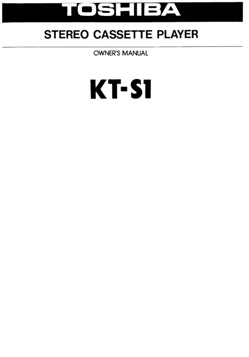
  9. Toshiba KT-S1 Mounting instructions

Toshiba KT-S1 Mounting instructions

fact.
Ny
5G
TOSHIBA
STEREO
CASSETTE
PLAYER
rr
BAA
reece
SERVICE
DATA
FILE
NO.100-152A
KT—S1
|
CONTENTS
1
OPERATING:
CONTROLS
*
25
oe
ck
ccis
eee
ald
pete
Pea
Mace
te
3
2.
DISASSEMBLY
INSTRUCTIONS
...........
00.00
eee
eee
nee
4
to
5
3..
BLOCK.-DIAGRAM
iio3<3
5.9
fee
de
acs hoe
ee
rete
aw!
She
a
ea
Sas
Oa
le
bes,
wes
6
4.
ALIGNMENT
INSTRUCTIONS
.........
2...
0c
cece
ee
ees
7
to
8
5.
ELECTRICAL
PARTS
LOCATION.............
02.00
ee
eee
eee
eanee
9,
11
5-1
CASSETTE
PLAYER
SECTION...
0...
0...
0...
ee
eens
9
5-2.
FM
TUNER
PACK
SECTION
........
0.0.0
cee
ee
eee
eee
11
6.
SCHEMATIC
DIAGRAM
.......
0...
0.0 eee
eee
ee
eee
ees
10,
12
6-1
CASSETTE
PLAYER
SECTION
...........
0.00.
e
eee
eee
ees
10
6-2.
FM
TUNER
PACK
SECTION
......
0...
0.
cee
ees
12
7.
MECHANISM
EXPLODED
VIEW....
2...
....
ee
ees
13
8.
MOTOR
REPLACEMENT
..........
2...
0
eee
ee
teens
14
9.
CABINET
EXPLODED
VIEW
....
2...
ee
eee
es
15,
18
9-1
CASSETTE
PLAYER
SECTION..........
0.0.
c
ce
ene
15
9-2
FM
TUNER
PACK
SECTION
...........
0.0...
ee
eee
eee
ene
18
10:
-IPARTS:
LIST
3
iti
kia
ea
2
G46
Palit)
Seana
Sauk
Wade
16, 17,
19,
22
10-1
MECHANISM
&
CASSETTE
RECORDER
CABINET..................
16
10-2:
“CASSETTE:
RECORDER:
sc
:3%0
55
cdots
as ne
See
Serhhe
s
8
a
akan
Res
17
10-3:
'EM-“TUNER:
PAGK.
je
2oc.%
64
ec
we
hace
ele
a
gee
oh
ape
ee,
ee
aie
a
Sac
ce
19
10-4
-ACCESSORIES
os
fx
seeing
os
Sach
Sa
ee
aye
eee
eres
he
es,
A
a
en
Meee
ae
22
11.
HEADPHONE
SECTION
............
0.2002
eee
ee
ee
20,
21
11-1
HEADPHONE
EXPLODED
VIEW
(TA,
TC,
AY).
.......
0.000
eee
ee
eas
20
11-2
HEADPHONE
PARTS
LIST
(TA,
TC,
AY).........
00000
eee
eee
eee
20
11-3.
HEADPHONE
EXPLODED
VIEW
(YY,
EY,
RY,
MY).
.........0000
00s
21
11-4
HEADPHONE
PARTS
LIST
(YY,
EY,
RY,
MY).
.........
0000
e
eee
21
Nameplate
(KT-S1)
Name
Label
(RP-S2)
(TA,
TC)
TOSHIBA
STEREO
CASSETTE
PLAYER
TOSHIBA
FM
STEREO
rere
TOSHIBA
CORPORATION
MADE
IN
JAPAN
USE
IN
COMBINATION
WITH
TOSHIBA
STEREO
CASSETTE
PLAYER
KT-S2
TOSHIBA
CORPORATION
FCC
10:
AUX9XAMOS1
TOSHIBA
MADE
IN
JAPAN
Name
Label
(RP-S2)
(AY,
YY,
EY,
MY)
TOSHIBA
Soshu
fa
FM
STEREO
TUNER
PACK
MODEL
NO.
RP-S2
USE
IN
COMBINATION
WITH
TOSHIBA
STEREO
CASSETTE
PLAYER
KT-S2
TOSHIBA
CORPORATION
MADE
IN
JAPAN
1.
OPERATING
CONTROLS
[RADIO]
tndicator
Lamp
[FUNCTION]
Switch
(RADIO/TAPE)
[PHONES]
Jack
[TAPE]
Selector
{BATT]
Indicator
[
>>
REVIEW]
Rewind/Review
Button
—e
[DC
IN
6V]
Jack
[
44
CUE]
Fast-Forward/Cue
Button
[TS]
Talk
Switch
Button
{M@
4
STOP/EJECT,
|
RADIO;
OFF}
Button
[<<
PLAY/|RADIO}
ON]
Button
[VOLUME]
Control
Figure
1.
[TUNING]
Knob
Tuning
Dial
Pointer
[FM
STEREO]
tndicator
[STEREO/MONO]
Switch
[LOCK]
Tab
TOBHMIBA
Figure
2.
ene
eam
KT-—S1
KT—S1
2.
DISASSEMBLY
INSTRUCTIONS
=
CABINET
BACK
REMOVAL
9
(A)
PAN
Screw
1.46
x
5mm,
Chrome
1.
Remove
screws
(A),
@),
©)
which
secure
cabinet
back
and
a
screw
D
which
holds
the
right
strap
to
detach
the
cabinet
back.
BID
Tapping
Screw
2¢
x
10mm,
Chrome
Figure
3.
0)
BID
Screw
Figure
4.
PAN
Screw
1.49
x
3mm,
Chrome
i:
Oe
e
Figure
5.
=@
CABINET
FRONT
REMOVAL
€)
BID
Tapping
Screw
1.
Remove
the
cabinet
back.
2.66
x
8mm,
Red
2.
Remove
screws
©,
®)
which
hold
mechanism
to
detach
the
cabinet
front.
Figure
6.
©
PAN
Screw
9
©)
PAN
Screw
=
HOW
TO
OPEN
THE
MAIN
P.C.
BOARD
1.4¢
x
3mm,
Black
1.4¢
x
4mm,
Black
1.
Remove
the
cabinet
back.
FLT
Screw
2.
Remove
the
screw
©
which
holds
the
P.C.
Board
1.4%
x
3.5mm,
Black
(H)
and
mechanism.
3.
Open
the
cassette
cover
and
remove
2
screws
)
which
hold
the
mechanism
cover
and
connector.
Figure
7.
KT—S1
TUNER
PACK
SERVICING
1.
Remove
the
specia!
screws
oO
at
the
cabinet
bottom
3.
Open
the
cassette
cover
and
set
the
cassette
in
the
of
the
tuner
pack.
cassette
compartment
with
the
cabinet
top
of
the
2.
Detach
the
cabinet
top
of
the
tuner
pack.
tuner
pack
removed.
In
this
state,
you
can
also
open
the
P.C.
Board
of
the
tuner
pack.
9
Screw
CG)
Special
Tapping
Screw
a)
a)
Figure
8.
Figure
10.
Figure
11.
3g
VNNJLNY
AQ
-90
=
"
Liva
40
a
oho
rer
ToS
ONON
Aldd'S
¥3MOd
noe
t
MS
J00W
aaa
|
j
YOLIANNOO
olanv-
olava
=
iol
fe
ONI
@
:
Haigh
Paci
ene
tae
|Gh
a
lo
s
.
Oo
,
al
a
©
2087
1nd
ee
AININ|ORY
4
~_|
Olav
WIVd
Y3NNL
Bare
10e7
KT—S1
=a
|
t
iy
1
-&
u0y
ily
<a
AN
eo
|
~
~
Oey
JWNI0A
os
nr
yal
iN
31d!
Z02S
:
HOLIMS
104
1NOD
5
wivh
JONVI1VE
i)
Hey
=
102¢S
|
Feme)
G
AWN
T0A
hoe
Balti
1
|
31ddI1
{
[
re
ir
liv
a
(od
<
CA
P89H
WOVE
AV Id
d8292V1
1060
1
¥3MOd
¥
3Yd
KT-S1
4.
ALIGNMENT
INSTRUCTIONS
TIO!
Z20!
Figure
13.
FM-IF
ALIGNMENT
1.
Turn
on
both
sweep
generator
and
oscilloscope,
and
allow
a
fifteen-minute
warm-up
period.
2.
Connect
the
RF
SWEEP
SIGNAL
OUTPUT
from
the
signal
generator
through
the
loop
antenna
to
the
receiver.
3.
Connect
the
oscilloscope
vertical
input
directly
to
the
test
point
Lor
R
and
connect
the
shielded
lead
to
the
test
point
Earth.
4.
Connect
the
SWEEP
VOLTAGE
OUTPUT
of
the
sweep
generator
to
the
oscilloscope.
5.
Proceed
as
outlined
in
the
FM-IF
ALIGNMENT
CHART.
FM-IF
ALIGNMENT
CHART
Signal
coupling
Equip.
Tuning
Connection
;
Pattern
Turn
the
coil
T102
fully
counterclockwise
to
obtain
a
single
peak.
Fig.
16
Connect
sweep
Sweep
Tuning
Knob
|
Set
scope
for
con-
generator
output
to
generator
of
|
fully
counter-|
necting
output
a
three-turn
loop
10.7
MHz
clockwise
signal
from
TUN
antenna
of
10cm
center
freq.
|
(Highest
OUT
to
vertical
Adjust
coil
T101
in
order
diameter.
with
10.7
Frequency.)
|
axis
of
scope
“V”
until
the
best
single
peak
MHz
marker.
and
sweep
gener-
is
obtained.
ator
output
to
Finally
turn
the
coi!
T102
horizontal
axis
to
obtain
S
curve.
Fig.
17
do
hae
1F
Sweep
Test
Receiver
FM
Swee
:
under
test
Generator
SWEEP
VOLTAGE
OUTPUT
.
3-turn
Loop
Antenna
located
near
the
L001
Figure
14.
ay
KT-S1
Generator
Couping
Hook-Up
S
Curve
Supply
Figure
16.
Figure
17.
FM-RF
ALIGNMENT
piguiesl
a:
.
Turn
on
the
signal
generator
and
the
VTVM,and
allow
a
fifteen-minute
warm-up
period.
Connect
the
signal
generator
output
through
a
75
ohm
dummy
antenna
across
FM
ANT.
‘Connect
the
VTVM
across
a
15K
ohm
dummy
load.
Adjust
the
signal
generator
frequency
as
indicated
in
FM-RF
ALIGNMENT
CHART,
and
maintain
a
sufficieni
FwWn
=
signal
output
level
to
provide
a
measurable
indication.
5.
Proceed
as
outlined
in
the
FM-RF
ALIGNMENT
CHART.
FM-RF
ALIGNMENT
CHART
Signal
Generator
Radio
Dia!
Setting
Adjustment
Remarks
87.5
MHz
Tuning
Knob
fully
OCS.
Coil
Counterclockwise
(Lowest
Frequency)
Eee
108
MHz
Tuning
Knob
fully
seam
Clockwise
; ,
(Highest
Frequency)
Repeat
steps
1
and
2
as
required.
Adjust
for
maximum
output
indication
Adjust
for
maximum
C004
output
indication
90MHz
RF
Coil
LoOo1
Adjust
for
maximum
+
Tune
to
signal
106
MHz
Ant.
Trim.
output
indication
C003
Repeat
steps
4
and
5
as
required.
CAUTION:
When
realigning
the
FM
Receiving
Frequency,
the
highest
end
of
the
frequency
range
should
not
be
more
than
108
MHz
and
the
lowest
end
of
the
frequency
range
should
not
be
less
than
87.5
MHz,
in
order
to
comply
with
FTZ
regulations
in
West
Germany.
ha
are
7
oF
MW
+o
A
(FM)
To
signa!
generator
:
50
ohm
se
(SG
imp.
50
ohm)
,
50
ohm
oO
receiver
| |
eae
See
eee
E
Lbe-e
ee
ee
ee
Sy
75
ohm
dummy
antenna
FREE
RUN
FREQUENCY
ALIGNMENT
Playback
Head
Adjust
R204
under
no
signal
condition
so
as
to
obtain
76
kHz
+
150
Hz.
\
PLAYBACK
HEAD
ADJUSTMENT
Adjusting
Screw
A
6.3
kHz
standard
tape
must
be
used
for
this
adjustment.
Connect
a
VTVM
or
an
oscilloscope
to
the
EXT
Speaker
jack
and
adjust
the
azimuth
by
using
a
phillips
screwdriver
to
maintain
the
maximum
output
voltage.
(4ff)
aoupyondo9
abosjon
Buryso,
AAI
ie
as
/
payooipul
soyjopdog
a1JAjONj9e]9
Ol/1=d
SPOJOsdW
UL
payDoipul
21D
sJo}190d09
|Iy¥
¢
%
GF‘
MB/]
WII}
UOGIDD
BJD
SJojsisal
ly
2
ASI]
AS1[AB'Y
[AGS
]AO'D|AB'S|
AOE]
AO
[ASO]
AO]
AO]
AO
AO'S|
AO
bl
ety
ety
it}
ol}
6
8
Z
9
S
Lae
ES
z
|
QOO!
=
¥
“SWYO
UL
payDoIpU]
21D
siojsisal
[IY
|
eopsloye
|
ALON
a
eh,
|
[unm
UA
vwog
inoqy
.
Buuny
awry
iy
YamOd
106S
wnuiW
yA
ee}
WWOIT
Inoqy
AW1d
19313
|
1199
aut
|“
yuoz
tea
rE
=
023
pp
oleva=
adit
1OE's
|
ADOU
4D
ses
09-9
ado,
pasn
«|
ywozl
inoay
oe
3
oe
ivi
|
20es
~
10es
|
wolipuoy
wawansoay)
_juazing
|
vousod_uoosed0
Pog"
ioaas
advi
|
201s
~
101s
;
juasing
uoljdwnsuoy.
UOls0dg
WON
YO}IMS
“ON
YOHMS
olbe4
goog
~ a
~
os/ev'0
sa
|
$089)
soea
‘|
£97001
d8c9lVi
1
a
vied
2060
Ao
20lutl
A-8Sb29S2
CP
2000
£0b0
ZY
.
-
YOLIBNNOD
(&)
19-0
Lee
®)
=
Gio
ze
Luavid-oivy
©
S02
UL
12b9
=
Bz
ozbd
g0eu
1000
Qv3H
yoveAv
Td
10°0
N81"
\¥9'SZ20
|
|
eovoze
you
£000
Jf
9069
8'1
i
albu
bt
i
13/209
O_O
WUON
ae
=
a
ou
a
ae
201s
You
[OUDIS
AW
Td
jy
(3WN70A]
(=)
Y9-8S2IS2
10°0
(3WM0A]
S
|
1060.
y3i1s
31ddl7
@
°
=Novdava
ORLS
Meg)
-duita
2,
|
O
I
eats
&
poe)
u
10°0
14002
2
1
nts
S1b9
os/ib'0
60£9
Adozb
|x2"1
62
I
ila
+{
2089
|socy
+
ggv2o
ce
ss
cs
‘
ses
He
:
a
200r
ie
i
aa
€°9/001
d8Z9LVL
73
bead
10b0
\
Move
90
lor
d00zz
ne
wef
0001}
+,
‘
LOVI
|
nore.
os/e'e
089
Los/e'e}
oe
av3H
20°
01/022
6169
200d
jis
fone
OVEN
Td
#089
£069
-
yi
-
098s
E
ie
yo
os/2vo
oh
iT)
-
oof
4189
“|
+
iofo
|
ery)
ye
os/e'e
sit>
|
sopsl
|
eopu
10b9
‘
WLIN/20DQ
C_O
WON
'
|
loss
dNV
Uamod-
sud
ar
yo}
joublS
AVI
7)
A
—
NOILOAS
YSAVId
ALLASSVO
—
<
if
INIVYOVIG
DILVINSAHOS
‘L-9
%
QUVOE
Id
AUFLIVE
a
wove
-
auvod
dd
NIVW
Yamod
20
:
1oor
OldVY/advL
|
Nollonnd
|
=
|
2
o
=]
>
|
|
Li.
206
‘1070
GUVO08
Dd
AWMIOA
QV3H
NOWEAV
Td.
@131HS
YOLOW
duvOd
Od
YOLVIIGNI
O10VY
HOLIMS
LOFTAS
Advi
101s
QuVOd
Id
AWMOA
OL
auvog
dd
YOIHD
AUSLLVE
—
NOILOAS
YSAV
1d
JLLASSVO
—
SNOILVOOT
SLYVd
WOIILOATA
‘l-G
KT—S1
KT—S1
28
ud
4021
yt
022
0
09
u
yinary
uado
Na
JOJSISAY
xX
juawysnly
902u
X
(48)
a2uny190d05
(A)
abD4]0A
sumer
|
al
(2
eel
"PayDIIPU!
10}19DdD>
I14h]O1}29}9
bp
Oleg
*SPDIDJOINIW
U}
PasDIIPU!
d4D
BdUDJIIDdDI
IW
¢
|
OOO!
=
¥
‘SWYO
Ul
payor
pu;
a10
adUD\sISAl
IY
Z
“UOI4ISOd
ONOW
---
(422182S
ONOW/
OSYSLS)
YHIMS
@PIIS
JOIS.
|
SajonN
§@
©
000
HO!
é
1027
wee
‘y
0129
HLuva
©
£2619S2
dVEZELVL
dVPIOLVL
z!
9¢zzsl
os”
2000
£
68
HO
do
d9
£109
0109
{f
1f
Oe
2004
2000
dWv
dl
W4
109
:
oso
W4
AJM
-MW-dVvI9ZVL
1010
yto-
ezelasz
£000
“I
1ee
vee
Pralt
eae
48
lose
N
802u
2024|
9024)
“
@)
pOeuL
£029|4.
o
rm
be
e200
£200!
i0s/!
‘1020
©
2029
9029
——
|edz9
He
od/2z0
z,
29)4
2029|-+
iL
O
GgcIsl
v
os/t
ogee
01
mI
Solu
)sol9
1000
6029
sou
eeu
20zu
1N0Y
Oxe=—Ht
Snot
|
1701
@
wae
oe
ed
ia
“ee
O6EZLI-14I
:
fF
AS'RILAZOL
AOL
Avl
AGIAS'E
LA'S
r
TER
J,
7
00.0,
00-4
OaYaLS
=O
:
ee
i
|
(lc
oe
ee
=:
°
onow
UO
.
-
300W
yaiud
dy
W4
H8SLI-
L4l
AEE
WV
XIN
W4
dWv
38
Wd
is
XdW
W4
u‘o-¢€2619sz
2000
y‘'O-E2619S2
1000
uo
‘A‘O
‘Y
‘NE-dezezvl
1020
YOLOSNOD
d9
!
£01y
P
}
“THW
2'0!
Yald-39
OC
—
NOILOAS
WOVd
HANNL
Ws
—
WVYSVIC
DILVINSHOS
*2-9
Figure
21.
—
NOILOAS
WOVd
YANNL
Ws
—
SNOILV9DOT
SLYVd
IWOlLOATA
*2-G
a
ae
i
ee
7.
MECHANISM
EXPLODED
VIEW
Figure
23.
bee
|
KT-—S1
KT-—S1
|
(1)
(2)
8.
MOTOR
REPLACEMENT
1.
MOTOR
PULLEY
REMOVAL
Put
a
preheated
soldering
iron
on
the
upper
part
of
the
pulley
to
melt
the
metal
glue
between
the
motor
pulley
and
the
shaft
of
the
motor
and
pull
the
motor
pulley
upward
strongly.
(See
Figure
24)
Caution:
Do
not
scorch
your
fingers.
2.
MOTOR
PULLEY
INSTALLATION
Maintain
a
gap
(1mm)
between
motor
and
motor
pulley
as
shown
in
Fig.25and
apply
a
little
metal
glue,
LOCTITE
601
(22964085)
from
the
top
of
the
motor
pulley.
Spread
the
glue
between
them
by
reciprocating
the
pulley
and
then
fix
it
while
keeping
the
adequate
gap
for
one
minute.
Caution:
Do
not
put
glue
around
part
A
in
Figure
25.
Soldering
tron
Motor
Pulley
——
Motor
Figure
24.
A
little
metal
glue—.
6
}
Motor
Pulley
Gap
{
Imm
=
®
Be
sure
to
keep
distance
of
Imm.
Motor
Figure
25.
—14—
9-1.
CABINET
EXPLODED
VIEW
—
CASSETTE
PLAYER
SECTION
—
Ss
Figure
26.
45
/
COVER,
MECHANISM
KT—S1
Symbol
No.|
Part
No.
10-1.
PARTS
LIST
—
MECHANISM
&
CASSETTE
PLAYER
CABINET
—
Description
Symbol
No.
Part
No.
Description
MECHANISM
PARTS
25779051
25779134
25735254
25756226
25756220
25764361
25764566
25773464
25776153
25712394
25712373
25713537
25713516
25713557
25791079
22703166
25726562
25775191
25776145
25776146
25776379
25776148
25776149
25776151
25776152
25791373
25782479
25782478
25782495
25782477
25782480
25726568
25755522
25761424
25764534
25773501
25717467
25717514
25717465
22125803
25758042
25764593
22217381
25726563
25772504
22707495
|
25736975
22707496
22701467
22707451
Cover,
Mechanism,
$1
Spring,
Holder
Spring
E
Ring,
1.5¢
Gear,
Cam
Gear,
Rewind
Washer
Washer
Spring,
Take-up
Lever
Spring
Reel
Ass’y,
Take-up
Reel
Ass’y,
Supply
Gear
Ass’y,
Fast
Lever
Ass‘y,
Detect
Lever
Ass‘y,
Take-up
Lever
Ass'y,
Detect
Washer
Roller
Wire,
Release
Spring
Spring
Spring
Spring
Spring
Spring
Spring
Lever
Ass’y,
Up
Drive
Button,
Fast
Forward
Button,
Stop
Button,
Talk
Switch
Button,
Playback
Button,
Rewind
Spacer,
2¢
x
3mm
Belt
Drive
Cushion,
Motor
Washer
Spring,
Pressure
Lever
Flywheel
Ass‘y
Holder
Ass’y,
Capstan
Lever
Ass‘y,
Pressure
Motor,
DC,
6V
Pulley,
Motor
Washer,
Thrust
Head,
Playback,
Ass’y,
HRPT-93
Spacer
Spring,
Head
Screw,
1.4¢
x
1.6mm,
FLT,
Chrome
Screw,
1.4¢
x
2.5mm,
PAN,
BLK
Screw,
2¢
x
3mm,
BID
Screw,
24
x
5mm,
BID
74
76
79
80
82
83
84
85
86
87
88
90
91
22707505
25776154
22707544
25764597
25773527
22707659
22707678
22703318
25781234
25735238
22707278
25726612
22707760
Screw,
2¢
x
6mm,
BID
Spring
Screw,
1.4¢
x
20mm,
FLT
Washer
Spring
Screw,
1.4¢
x
3.5mm,
FLT,
BLK
Screw,
1.4¢
x
1.6mm,
FLT,
BLK
Washer
Conector
Washer
Screw,
24
x
3mm,
BID,
Chrome
Roller
Screw,
1.4¢
x
2.5mm,
Special
CABINET
PARTS
25881317
25881265
25881266
25777072
25779217
25830236
25846515
25846516
25846544
25846554
25847248
25838796
25837674
22703319
22707525
22707593
22707595
22707612
22707614
22707738
22707741
22701245
22707486
22707740
22900107
25808073
22900140
25766067
Cabinet
Assy,
Front
Cabinet
Ass’y,
Back
Cassette
Cover
Ass’y
Spring,
Eject
Spring,
Battery
Arm,
Eject
Nut,
Plate
Hinge
Bracket,
Hold
Strap,
Right
Strap,
Left
Cover,
Battery
Knob,
Variable
Volume
Washer
Screw,
2.6¢
x
8mm,
BID
Tapping,
RED
Screw,
1.49
x
5mm,
PAN
FLT,
Chrome
Screw,
2¢
x
8mm,
BID,
Chrome
Screw,
1.4¢
x
3mm,
PAN
FLT,
BLK
Screw,
1.4¢
x
4mm,
PAN
FLT,
BLK
Screw,
1.4¢
x
3mm,
PAN,
Chrome
Screw,
2¢
x
10mm,
BID,
Tapping,
Chrome
Screw,
2¢
x
6mm,
BID,
Tapping
Screw,
1.74
x
4mm,
FLT
Screw,
1.4¢
x
2.5mm,
PAN,
Chrome
Label,
Caution,
C
Nameplate
Label,
Caution,
DC
Power
Washer
|
KT—S1
KT-S1
|
10-2.
PARTS
LIST
—
CASSETTE
PLAYER
SECTION
—
9-2.
CABINET
EXPLODED
VIEW
—
FM
TUNER
PACK
SECTION
—
Symbol
No.
Part
No.
Description
Symbol
No.
Part
No.
Description
TRANSISTORS,
ICS
AND
DIODES
0401,
402
Q403
Q901
D001
Doo2
D003
1C,
TA7628P
Transistor,
25C2458-Y
Transistor,
2SC2458-GR
Diode,
TLR205,
LED,
RED
Diode,
TLR102,
LED,
RED
Diode,
0225.6A
C904
C905
C906
C907
22360346
22360344
22440405
22360344
BL,
0.047mfd,
25V,M
BL,
0.0imfd,
25V,M
EL,
220mfd,
6.3V
BL,
0.01imfd,
25V,
M
noted.
RESISTORS
All
resistors
are
carbon
film
1/8W,
+5%
unless
otherwise
ELECTRICAL
PARTS
J001
J002
$101
~
102
$201
$301
$901
L301
L304
EPO1
22163721
22163876
22195692
22195886
22195710
22195432
22292136
22294361
22191997
Jack,
DC
Power
(DC-6V)
Jack,
3.59,
Stereo
Headphone
Switch,
Slide,
Tape
Select
Switch,
Slide,
Muting
Switch,
Slide,
Tape/Radio
Switch,
Leaf,
Power
Coil,
RT-51-2136
Coil,
FM,
RF
PC
Board,
Battery
Abbreviations:
CAPACITORS
D
=
+0.5pF,
K
=
+10%,
M=+20%
CD
=
Ceramic
Disk,
EL
=
Electrolytic
BL
=
Barrier
Layer
C301,
302
C303,
304
C305,
306
C307,
308
C309,
310
C311,
312
C313,
314
C315
C316
C317,
318
C401,
402
C403,
404
C405,
406
C407,
408
C409,
410
C411,
412
C413,
414
C415,
416
C417
C418
C419
C420
C421
C901
C902
C903
22360367
22440398
22440277
22360362
22440271
22440279
22440399
22362180
22360371
22440271
22440398
22440398
22360624
22360366
22360365
22360574
22360344
22360367
22360344
22440398
22440398
22440279
22360344
22440405
22440399
22440404
CD,
2200pF,
50V,
K
EL,
3.3mfd,
50V
EL,
22mfd,
6.3V
CD,
470pF,
50V,
K
EL,
0.47mfd,
50V
EL,
47mfd,
6.3V
EL,
100mfd,
6.3V
CD,
18pF,
50V,
K
CD,
4pF,
50V,
D
EL,
0.47mfd,
50V
EL,
3.3mfd,
50V
EL,
3.3mfd,
50V
CD,
0,002mfd,
50V,
K
CD,
0.001mfd,
50V,
K
CD,
100pF,
50V,
K
BL,
6800pF,
25V,
K
BL,
0.01mfd,
25V,
M
CD,
2200pF,
50V,
K
BL,
0.01mfd,
25V,
M
EL,
3.3mfd,
50V
EL,
3.3mfd,
50V
EL,
47mfd,
6.3V
BL,
0.01mfd,
25V,
M
EL,
220mfd,
6.3V
EL,
100mfd,
6.3V
EL,
220mfd,
10V
R301
R302
R303
R304
R305
R306
R307
R308
R309,
310
R311
R401,
402
R405,
406
R407,
408
R409,
410
R411,
412
R413,
414
R415
R416
R417
R418
R419
R901
|
22540531
22550201
22550171
22540500
22550182
22540511
22540490
22550161
22657219
22658623
22540504
22540525
22540544
22540522
22540520
22540500
22550181
22550202
22550192
22550184
22550191
22540513
56K
ohm
56K
ohm
150
ohm
150
ohm
1.2K
ohm
1.2K
ohm
22
ohm
22
ohm
10K
ohm,
A,
Variable
Volume
30K
ohm,
Variable
Volume
330
ohm
18K
ohm
680K
ohm
10K
ohm
6.8K
ohm
150
ohm
1K
ohm
68K
ohm
10K
ohm
1.8K
ohm
6.8K
ohm
1.8K
ohm
Figure
27.
—18—
KT-—S1
10-3.
PARTS
LIST
—
FM
TUNER
PACK
—
Symbol
No.|
Part
No.
Description
Symbol
No.|
Part
No.
Description
C005
22360563
|
CD,
18pF,
50V,
D
C006
22360366
|
CD,
1000pF,
50V,
K
C007
22360372
|
CD,
6pF,
50V,
D
C008
22360366
|
CD,
1000pF,
50V,
K
C009
22360329
|
BL,
0.022mfd,
31.5V,
M
C010
22360372
|
CD,
6pF,
50V,
D
C011
22360327
|
BL,
0.01mfd,
25V,
M
C012
22360591
|
CD,
24pF,
50V,
D
C013
22360368
|
CD,
6pF,
50V,
D
C014
°
22360346
|
BL,
0.047mfd,
12.5V,
M
C015
22360329
|
BL,
0.022mfd,
31.5V,
M
C101,
102,
|
22360327
|
BL,
0.01mfd,
25V,
M
103
C104
22360346
|
BL,
0.047mfd,
12.5V,
M
C105
22360365
|
CD,
100pF,
50V,
K
C201
22440276
|
EL,
10mfd,
16V
C202
22440320
|
EL,
0.22mfd,
50V
C203
22440271
|
EL,
0.47mfd,
50V
C204
22380070
|
PS,
1000pF,
125V,
D
C205
22440272
|
EL,
1mfd,
50V
C206,
207
|
22360330
|
BL,
0.033mfd,
25V,
M
C208,
209
|
22440272
EL,
1mfd,
50V
C210
22440277
|
EL,
22mfd,
6.3V
CABINET
PARTS
|
22881067
|Cabinet,
Upper
22847374
|
Plate,
Dial
22824362
|
Knob,
Tuning
22161681
|
Connector,
6P
22713103
|
Plate,
Lock
22884082
|
Knob,
Lock
22881054
|
Cabinet,
Bottom
22866177
|Name
Label
(TA/TC)
22866178
|Name
Label,
(YY/AY/EY/MY)
22701314
|Screw,
2¢
x
3mm,
BID
22707555
|Screw,
1.7¢
x
3.5mm,
Special
22707662
|Screw,
Special,
Tapping
22702180
|
Nut,
Special
22707614
|Screw,
1.4¢
x
4mm,
Special,
BLK
22758293
|
Cushion,
Tube
22900107
|Label,
Caution,
C
TRANSISTORS,
I1CS
AND
DIODES
0001,
002,
Transistor,
25C1923-0,
R
003
Q101
IC,
TA7614AP-W-W/Y
0201
IC,
TA7323P-BN,
R,
O, Y,
GR
D001
Diode,
1S1555V
D002
Diode,
1$2236
D201
Diode,
TLR123,
LED,
RED
RESISTORS
All
resistors
are
carbon
film
1/8W,
+5%.
K
=
1000
ROO1
22540518
|
4.7K
ohm
R002
22540497
|
82
ohm
ROO3
22540522
|
10K
ohm
R004
22540525
|
18K
ohm
ROOS
22540523
|
12K
ohm
R006
22540530
|
47K
ohm
R007
22540538
|
220K
ohm
R101
22540508
|
680
ohm
R102
22540494
|
47
ohm
R103
22550172
|
180
ohm
R104
22540180
|
150
ohm
R105
22540218
|
220K
ohm
R106
22540523
|
12K
ohm
R202
22540510
|
1K
ohm
R203
22540522
|
10K
ohm
R204
22658593
|
4.7K
ohm,
Semi-fixed
Variable
R205
22540504
|
330
ohm
R206
22540533
|
82K
ohm,
(TA7323P-GR)
R206
22540535
|
120K
ohm,
(TA7323P-Y)
R206
22540538
|
220K
ohm,
(TA7323P-0)
R206
'
|
22540543
|
560K
ohm,
(TA7323P-R)
R207,
208
|
22540516
|
3.3K
ohm
ELECTRICAL
PARTS
LOO1a
22294416
|
Coil,
FM,
LH8403R
LOO1b
22294414
|
Coil,
FM,
LH8402R
LO02a
22294415
|
Coil,
FM,
Oscillator
LO02b
22294413
|
Coil,
FM,
Oscillator
L101,
201
22241013
|
Coil,
104H
T101
22265811
|
IF
Transformer,
FM,
175811
T102
22267390
|
IF
Transformer,
FM,
1T7390
$101
22195556
|
Switch,
Slide,
Stereo/Mono
Z001
22153197
|
Filter,
FM,
10.7
MHz,
Band-Pass
2201
22153067
|
Filter,
Ceramic,
FM,
10.7
MHz
(AY/YY/EY/MY)
2201
22153122
|
Filter,
Ceramic,
FM,
10.7
MHz
(TA/TC)
CAPACITORS
D=+0.5pF,
K=+10%,
M=+20%
ABBREVIATIONS:
CD
=
Ceramic
Desk,
EL
=
Electrolytic
BL
=
Barrier
Layer,
PS
=
Polystyrene
C001,
002
22308206
|
Pory
Variable
Capacitor
C003
22309175
|
Trimmer
C004
22309159
|
Trimmer
Note:
FM
Tuner
pack
for.“RY”
is
optional.
KT—S1
11-1.
HEADPHONE
EXPLODED
VIEW
—
TA,
TC,
AY
—
Figure
28.
=
CARE
FOR
UNIT
ASSEMBLY
AND
REPLACEMENT
OF
CORD
WITH
PLUG
1.
Insert
tweezers
into
dent
of
unit
case
and
detach
2.
Unsolder
the
back
of
assembly
to
remove
the
cord
the
assembly
from
the
case
with
tweezers
lifting
up.
with
plug.
Unit
Assembly
Unit
Assembly
Cord
with
Plug
van
mK?
Figure
29.
Figure
30.
11-2.
HEADPHONE
PARTS
LIST
Symbol
No.|
Part
No.
Description
Symbol
No.
Description
381
22810066
|
Head
Band
Ass’y,
(TA/TC/AY)
384
22810069
|
Unit
Case,
(TA/TC/AY)
22810070
|
Cord
Ass’y
With
Plug,
(TA/TC/AY)
382
228
10067
|
Ear
Pad
Set,
(TA/TC/AY)
385
383
228
10068
|
Unit
Ass’y,
(TA/TC/AY)
—20—
KT—S1
11-3.
HEADPHONE
EXPLODED
VIEW
—
YY,
EY,
RY,
MY
—
=
CARE
FOR
UNIT
ASSEMBLY
AND
REPLACEMENT
OF
CORD
WITH
PLUG
Groove
between
case
A
and
case
B.
As
for
assembly
of
headphone
case,
case
A
(net
side)
is
combined
with
case
B
(frame
side)
by
the
claw
of
case
B.
case
A
(1)
Insert
the
screwdriver
{
—
)
into
the
hole
of
case)
and
push
down
the
tip
of
screwdriver
in
the
@
Insert
a
slender
screw-
direction
of
arrow
by
the
principle
of
lever
to
case
B
driver
into
the
groove.
make
a
groove
between
case
A
and
case
B.
;
:
5
j ;
;
@)
Insert
a
slender
screwdriver
and
push
its
top
in
the
(2)
Insert
a
slender
screwdriver
into
the
groove
Figure
32.
direction
oF
akon.
and
unhook
the
claw
with
the
case
A
raising
up
:
ere
Note:
When
disassembling
the
case
with
a
screwdriver,
in
the
direction
of
arrow
©.
take
enough
care
not
to
damage
the
case
or
unit
assembly
in
the
case.
11-4.
HEADPHONE
PARTS
LIST
Symbol
No.|
Part
No.
Description
Symbol
No.
Description
381
22810061
|
Head
Band
Ass’y,
(YY/EY/RY/
384
22810064
|
Case
Set,
(YY/EY/RY/MY)
385
22810065
|
Cord
Ass’y
With
Plug,
382
22810062
|
Ear
Pad
Set,
(YY/EY/RY/MY)
(YY/EY/RY/MY)
383
22810063
|
Unit
Ass’y,
(YY/EY/RY/MY)
Symbol
No.
10-4.
PARTS
LIST
—
ACCESSORIES
—
Part
No.
Description
Symbol
No.
Part
No.
Description
ACO1
ACO1
ACO1
ACO1
ACO1
22903139
|
Owner's
Manual,
(TA)
22903140
|
Owner’s
Manual,
(TC)
22903141
|
Owner’s
Manual,
(YY/EY/MY)
22903142
|
Owner’s
Manual,
(RY)
22903143
|
Owner’s
Manual,
(AY)
MANUFACTURED
BY
TOSHIBA
CORPORATION
2-1,
GINZA
5-CHOME,
CHUO-KU,
TOKYO
104,
JAPAN
ACO2
AC03
AC04
AC05
22105367
|
Demonstration
Tape
22991088
|
Carring
Case
22991086
|
Belt,
Strap
22906288
|
Caution
Label
PRINTED
IN
JAPAN
22905062
Oct.,
1981

Other manuals for KT-S1

1

Other Toshiba Cassette Player manuals

Toshiba RT-200S Mounting instructions

Toshiba

Toshiba RT-200S Mounting instructions

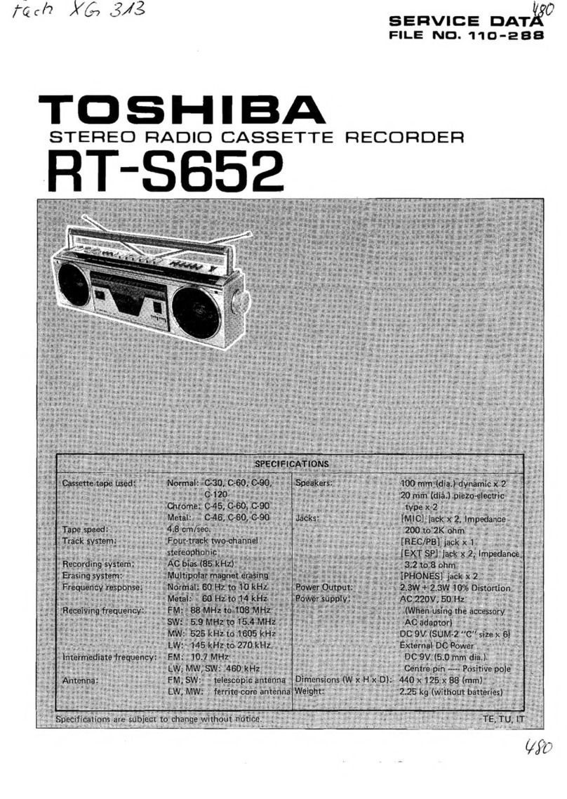
Toshiba RT-S652 User manual

Toshiba

Toshiba RT-S652 User manual

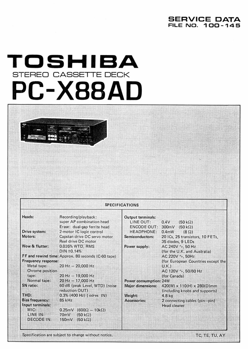
Toshiba PC-X88AD Mounting instructions

Toshiba

Toshiba PC-X88AD Mounting instructions

Toshiba PC-E70 User manual

Toshiba

Toshiba PC-E70 User manual

Toshiba KT-R2 User manual

Toshiba

Toshiba KT-R2 User manual

Toshiba RT-S933 User manual

Toshiba

Toshiba RT-S933 User manual

Toshiba D-VR660KU User manual

Toshiba

Toshiba D-VR660KU User manual

Toshiba KT-4568 Mounting instructions

Toshiba

Toshiba KT-4568 Mounting instructions
Toshiba SD-V280 User manual

Toshiba

Toshiba SD-V280 User manual

Toshiba KT-S1 User manual

Toshiba

Toshiba KT-S1 User manual

Toshiba SD-22VB User manual

Toshiba

Toshiba SD-22VB User manual

Toshiba SD-V594SU User manual

Toshiba

Toshiba SD-V594SU User manual

Popular Cassette Player manuals by other brands

Harman Kardon CD191 owner's manual

Harman Kardon

Harman Kardon CD191 owner's manual

Sony TC-TX373 operating instructions

Sony

Sony TC-TX373 operating instructions

Sony TC-D505 Service manual

Sony

Sony TC-D505 Service manual

Kenwood KX-W6050 Service manual

Kenwood

Kenwood KX-W6050 Service manual

Panasonic CQ-858EG Service manual

Panasonic

Panasonic CQ-858EG Service manual

Philips AZ 1564 user manual

Philips

Philips AZ 1564 user manual

Aiwa CSD-TD31 Service manual

Aiwa

Aiwa CSD-TD31 Service manual

Sony TC-FX120 operating instructions

Sony

Sony TC-FX120 operating instructions

Coodmans GPS217PLLR instruction manual

Coodmans

Coodmans GPS217PLLR instruction manual

Panasonic RQ-X01 operating instructions

Panasonic

Panasonic RQ-X01 operating instructions

Sony Pressman TCM-929 Service manual

Sony

Sony Pressman TCM-929 Service manual

Pioneer KEH-P7020R Service manual

Pioneer

Pioneer KEH-P7020R Service manual

Coby 244532 instruction manual

Coby

Coby 244532 instruction manual

Pioneer CT-7R Service manual

Pioneer

Pioneer CT-7R Service manual

Aiwa HS-PXM2000 Service manual

Aiwa

Aiwa HS-PXM2000 Service manual

Aiwa HS-GS192 Service manual

Aiwa

Aiwa HS-GS192 Service manual

Nakamichi CR-4 Service manual

Nakamichi

Nakamichi CR-4 Service manual

Onkyo TA-RW255 - Dual Cassette Deck Service manual

Onkyo

Onkyo TA-RW255 - Dual Cassette Deck Service manual

manuals.online logo
manuals.online logoBrands
  • About & Mission
  • Contact us
  • Privacy Policy
  • Terms and Conditions

Copyright 2025 Manuals.Online. All Rights Reserved.