Toshiba Aplio SSA-770A User manual

No. 2D730-148E”O
SERVICE MANUAL
FOR
DIAGNOSTIC ULTRASOUND SYSTEM
MODELS SSA-700A/SSA-770A
(2D730-148E”O)
TOSHIBA MEDICAL SYSTEMS CORPORATION
@ITOSHIBA MEDICAL SYSTEMS CORPORATION 2001-2008
ALL RIGHTS RESERVED

No. 2D730-148E*O
IMPORTANT!
1. No part of this manual may be copied or reprinted, in whole or in pat-t,
without written permission.
2. The contents of this manual are subject to change without prior notice
and without our legal obligation.
C-l *

No. 2D730-148E*O
REVISION RECORD
REV. DATE
REASON PAGE
SER. DOC.
(MM/W)
/AUTHOR CHANGED
No. PRODUCT.
INI. 1 07/‘01 1 Mr. Kuramata ------- I
*A 1I/‘01 support of VI .5 Mr. Tamura I I
*B 04/‘02
I I
Support of V2.0 for SSA-770A (and Mr. Ogasawarai 1 1
additions)
*C
*D
06/‘02 Mr. Shibanuma
1I/‘02 support of v3.0 Mr. Ogasawara
*E
*F
07/‘03 support of v4.0 Mr. Nakai
08/‘03 Change of the AC/DC power supply etc.
Mr. Fujiwara
*G 1 IO/‘03 IDue to change of company name
*H IO/‘03 Change of the AC/DC power supply Mr. Fujiwara I I
*I 1 12/‘03 Support of V5.0
*J 02/‘04 Addition of section 17 Mr. Nakai I I
“K 1 06/‘04 Changes to section 17
*L
*M
02/‘05 Support of V6.0 Mr. Nakai KD-WPX
12/‘05 support of v7.0 Mr. Nakai
*N 09’06 Addition of systems with the LCD monitor Mr. Nakai
02/‘08 Support of Doppler Measurement Preset TM-WP2
Mr. Nakai
R-l

No. 2D730-148E*O
Safety Precautions
1. Meaning of Signal Words
ln this manual, the signal words
DANGER, WARNING,
and
CAUTION
are used regarding
safety and other important instructions. The signal words and their meanings are defined as follows.
Please understand their meanings clearly before reading this manual.
I
Signal word I Meaning
I
ADANGER
Indicates an imminently hazardous situation which, if not avoided, will
result in death or serious injury.
I
AWARNING
Indicates a potentially hazardous situation which, if not avoided, could
result in death or serious injury.
ACAUTION
Indicates a potentially hazardous situation which, if not avoided, may
result in minor or moderate injury.
CAUTION Indicates a potentially hazardous situation which, if not avoided, may result in
property damage.
2. Meaning of Safety Symbols
Symbol 1 Description
ir I
Type-B applied part
cl
fi
A
!
* Type B when Type-B applied part is connected.
The PCG sensor and pulse sensor that can be connected
to this system are Type-B applied parts.
Type-BF applied part
* Type BF when Type-BF applied part is connected.
All ultrasound transducers, ECG cables, and respiration
sensors that can be connected to this system are Type-BF
applied parts.
“Attention” (Refer to the operation manual.)
S-l

No. 2D730-148E*O
3. Safety Precautions
Please observe the following precautions to ensure the safety of service engineers as well as operators
when using this system.
I
&ANGER: Do no use flammable gases such as anesthetics, or flammable liquids sucht
as ethanol, near this product, because there is danger of explosion. I
,&ARNING: 1. Information concerning the terminal to which the potential equalization
conductor is to be connected ( + ):
To use another medical device in combination with this system, an
equipotential wire for connecting to an equipotential bus must be
supplied. For more information, contact your TOSHIBA representative.
* Be sure to connect the potential-equalization lead wire before inserting
the equipment power plug into the receptacle. Also, be sure to remove
the equipment power plug from the receptacle before disconnecting
the wire to avoid electrical shock.
2. Information concerning the functional earth terminal
(6):
Use of the functional earth terminal as protective earth is not allowed in
Europe. The system should be connected according to local
requirements.
3. Do not connect this system to outlets with the same circuit breakers and
fuses that control current to devices such as life-support systems. If this
system malfunctions and generates an overcurrent, or when there is an
instantaneous current at power ON, the circuit breakers and fuses of the
building’s supply circuit may be tripped.
4. Do not connect to the system transducers other than those specified by
TOSHIBA, to prevent accidents such as fire.
5. Do not subject the transducers to knocks. Use of defective transducers
may cause an electric shock.
ACAUTION:
1. Malfunctions due
to
radio waves
(1) Use of radio-wave-emitting devices in the proximity of this kind of
medical electronic system may interfere with its operation. Do not bring
or use devices which generate radio waves, such as cellular telephones,
transceivers, and radio controlled toys, in the room where the system is
installed.
(2) If a user brings a device which generates radio waves near the system,
they must be instructed to immediately turn OFF the device. This is
necessary to ensure the proper operation of the system.
s-2

No. 2D730-148E*O
A
- CAUTION:
2. Be sure to install the system on a level floor and lock the casters. If this is
not done, the system may move, injuring the service personnel.
3. Move the system forward or backward only. If the system is moved to the left
or right, it may fall, causing injury. In addition, be sure to fix the moving
sections such as the operating panel before moving the system. If such
sections move, they may catch the hands or fingers of the persons moving
the system, possibly causing injury.
4. To prevent electric shock, do not connect the peripheral units (video printer,
VCR, etc.) to an external outlet. Peripheral units should be connected to the
service outlet of the system or the optional isolation transformer. For the
connection procedures, contact your TOSHIBA representative.
5. The service outlet of the main unit is intended solely for recommended
peripheral units. Do not connect devices other than recommended
peripheral units to the service outlet. Connecting devices other than those
recommended may cause the consumption current to exceed the power
capacity of the main unit, possibly resulting in malfunction.
6. Do not place any objects on top of the monitor. They may fall, causing
injury.
7. Do not allow fluids such as water to contact the system or peripheral
devices. Electric shock may result.
8. Do not handle the system with wet or moist hands. Electric shock may
result.
9. The monitor is a heavy unit. Two persons are required when mounting or
removing the monitor. If a worker mounts or removes the monitor alone,
he/she may be injured.
10. Be sure to turn OFF the power breaker and disconnect the mains plug from
the outlet before removing the covers of the main unit and performing
internal wiring.
11. When discarding any part of this system, follow all applicable local
regulations.
12. Wear protective gloves to ensure safety and prevent infection when
performing unit replacement, board replacement, internal wiring, or cleaning.
13. Wait at least 30 seconds after turning OFF the power breaker and
disconnecting the mains plug from the outlet before replacing the battery.
Otherwise, an electric shock may result.
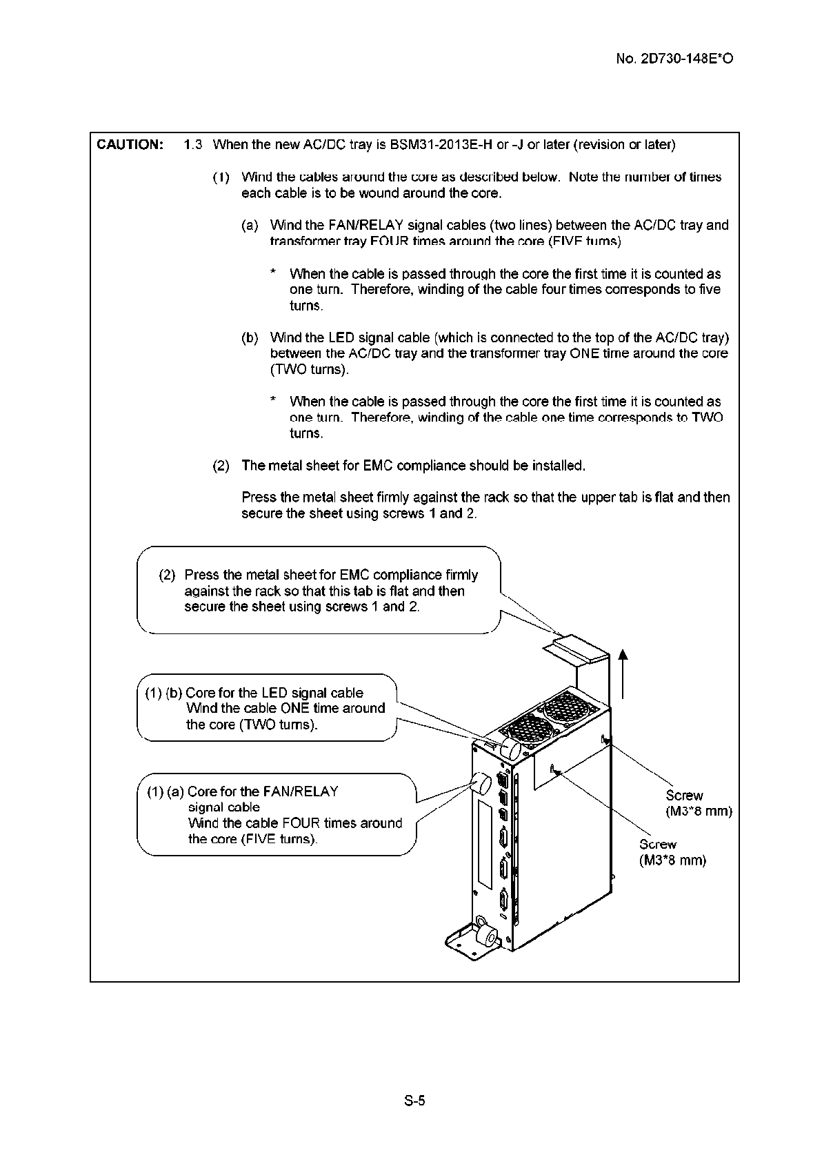
CAUTION: I. When replacing the AC/DC tray of the SSA-770A, check the revision number of the
AC/DC tray supplied for replacement and follow the appropriate procedure according to
the revision number.
1.I When the new AC/DC tray is BSM31-2013E (no revision)
The AC/DC tray is not compatible and must not be used to replace the existing tray.
s-3

No. 2D730-148E*O
CAUTION: 1.2 If AC/DC tray BSM31-2013E-G or BSM31-2013E-I is supplied
(1) Wind the cables around the core as described below.
(a) Wind the FAN/RELAY signal cables (two lines) between the AC/DC tray and
transformer tray ONE time around the core (TWO turns).
* When the cable is passed through the core the first time it is counted as
one turn. Therefore, winding of the cable one time corresponds to TWO
turns.
(b) Wind the LED signal cable (which is connected to the top of the AC/DC tray)
between the AC/DC tray and the transformer tray ONE time around the core
(TWO turns).
* When the cable is passed through the core the first time it is counted as
one turn. Therefore, winding of the cable one time corresponds to TWO
turns.
(2) The metal sheet for EMC compliance should not be installed.
1) (b) Core for the LED signal cable
(1) (a) Core for the FAN/RELAY
Wind the cable ONE time around
s-4

No. 2D730-148E*O
CAUTION: 1.3 When the new AC/DC tray is BSM31-2013E-H or -J or later (revision or later)
(1) Wind the cables around the core as described below. Note the number of times
each cable is to be wound around the core.
(a) Wind the FAN/RELAY signal cables (two lines) between the AC/DC tray and
transformer tray FOUR times around the core (FIVE turns).
* When the cable is passed through the core the first time it is counted as
one turn. Therefore, winding of the cable four times corresponds to five
turns.
(b) Wind the LED signal cable (which is connected to the top of the AC/DC tray)
between the AC/DC tray and the transformer tray ONE time around the core
(TWO turns).
* When the cable is passed through the core the first time it is counted as
one turn. Therefore, winding of the cable one time corresponds to TWO
turns.
(2) The metal sheet for EMC compliance should be installed.
Press the metal sheet firmly against the rack so that the upper tab is flat and then
secure the sheet using screws1 and 2.
(2) Press the metal sheet for EMC compliance firmly
against the rack so that this tab is flat and then
secure the sheet using screws 1 and 2.
/;1) (b) Core for the LED signal cable
Wind the cable ONE time around
the core (TWO turns). \I----:.:,
(1) (a) Core for the FAN/RELAY
Wind the cable FOUR times around
the core (FIVE turns).
Screw
\ (M3*8 mm)
Screw
(M3*8 mm)
S-5

No. 2D730-148E*O
CAUTION: 2. Voltage setting for replacing the transformer tray and TRANS-unit
The switches used to select the output voltage according to the input voltage are
installed on the transformer tray and the TRANS-unit.
When the switches of the replacement units (transformer tray and TRANS-unit) are not
set correctly, the power supply may not start up correctly, or a malfunction of the
connection equipment may result. Be sure to check the settings.
For the transformer tray
100 to 120 VAC “115” must be displayed on Sl and S3.
The direction of S2 must be the same as that of Sl
230 VAC “230” must be displayed on Sl and S3.
The direction of S2 must be the same as that of S3
For the TRANS-unit
100 to 120 VAC “115” must be displayed.
“115” must be displayed.
The direction must be the same as that of Sl and S2
230 VAC “230” must be displayed.
“230” must be displayed.
The direction must be the same as that of Sl and S2
S-6 *

No. 2D730-148E*O
CONTENTS
Page
Safety precautions ________________________________________-------------------------------------------------------------------S-1
1. INTRODUCTION ________________________________________--------------------------------------------------------------1-I
1.1 Outline ________________________________________-------------------------------------------------------------------1-I
1.2 PWB Configuration of Each Unit ________________________________________----------------------------------I-2
2. BLOCK DIAGRAM ________________________________________------------------------------------------------------------2-I
3. DISASSEMBLY AND REMOVAL PROCEDURES ________________________________________---------------------3-I
3.1 Name of Each Section ------__--------------~~~--------------~~~--------------~~--------------~~~------------ 3-l
3.2 Removing the Covers ________________________________________------------------------------------------------3-5
3.2.1 For the SSA-77OA-------------------------------------------------------------------------------- 3-5
3.2.2 For the SSA-7OOA-------------------------------------------------------------------------------- 3-7
3.3 Removing the Handle ________________________________________----------------------------------------------3-10
3.3.1 For the SSA-77OA------------------------------------------------------------------------------ 3-l 0
3.3.2 For the SSf+7OOA ________________________________________--------------------------------------3-l 1
3.4 Removing the Monitor Unit ________________________________________---------------------------------------3-12
3.4.1 Removing the monitor unit (for systems with the CRT monitor)---------------------- 3-12
3.4.2 Removing the monitor unit (for systems with the LCD monitor)---------------------- 3-14
3.4.3 Removing the LCD monitor arm ________________________________________---------------------3-15
3.4.4 Adjusting the LCD monitor arm vertical movement resistance ----------------------- 3-l 8
3.5 Removing the Operating Panel ________________________________________----------------------------------3-19
3.5.1 For the SSf+77OA ________________________________________--------------------------------------3-l 9
3.5.2 For the SSf+7OOA ________________________________________--------------------------------------3-23
3.6 Disassembling the Operating Panel ________________________________________----------------------------3-24
3.6.1 Removing the lower cover ________________________________________----------------------------3-24
3.6.2 Removing the panel ________________________________________---------------------------3-27upper
3.6.3 Removing the handle -----------___--------------~~~--------------~~--------------~~~---------- 3-28
3.6.4 Removing the trackball section ________________________________________----------------------3-29
3.6.5 Removing the PWBs (B) and (G) -------------___--------------~~--------------~~~---------- 3-30
3.6.6 Removing the keyboard----------------------------------------------------------------------- 3-31
-a-

No. 2D730-148E*O
3.7
3.8
3.9
3.10
3.11
3.12
3.13
3.14
3.15
3.16
3.17
3.18
3.19
3.20
3.21
3.20.2 For the SSf!,-7()()p, ________________________________________--------------------------------------3-61
Cleaning the Air Filters -----__--------------~~~--------------~~~--------------~~--------------~~~---------- 3-62
3.22 Cleaning the panel ----------__--------------~~~--------------~~~--------------~~--------------~~~---------- 3-63
CONTENTS - continued
Page
3.6.7 Removing the keyboard ________________________________________-------------------------------3-32
3.6.8 Removing the LCD /.l,SSY ________________________________________----------------------------3-33
3.6.9 Removing the PWBs (C), (D), and (E)________________________________________-------------3-34
3.6.10 Removing the near/away slide lever ________________________________________---------------3-35
3.6.11 Removing the up/down slide lever ________________________________________------------------3-36
3.6.12 Mounting the switch cover ________________________________________----------------------------3-37
Removing the PWB Rack--------------------------------------------------------------------------------- 3-38
Removing the PWBs ________________________________________-----------------------------------------------3-40
Removing the TI--------------------------------------------------------------------------------------------- 3-41
Removing the 10 -------------__--------------~~~--------------~~~--------------~~--------------~~~---------- 3-42
Removing the HDD Unit ________________________________________-------------------------------------------3-43
Removing the Battery-------------------------------------------------------------------------------------- 3-44
Removing the AC-DC Unit ________________________________________----------------------------------------3-45
Removing the PSA and PSD ________________________________________-------------------------------------3-48
Removing the Transformer ________________________________________---------------------------------------3-49
Removing the MO ________________________________________--------------------------------------------------3-50
Removing the Front panel ________________________________________----------------------------------------3-51
3.17.1 For the SSf+77OA ________________________________________--------------------------------------3-51
3.17.2 For the SSf!,-7OOA________________________________________--------------------------------------3-54
Removing the Rear panel ________________________________________-----------------------------------------3-55
Removing the PHYSlO Unit ________________________________________--------------------------------------3-56
3.19.1 For the SSf+77()A ________________________________________--------------------------------------3-56
3.19.2 For the SSf+7OOA ________________________________________--------------------------------------3-57
Removing the Caster Units ________________________________________---------------------------------------3-58
3.20.1 For the SSA-77OA------------------------------------------------------------------------------ S-58
-b-

No. 2D730-148E*O
CONTENTS - continued
Page
3.22.1
Cleaning of key tops ________________________________________----------------------------------- 3-63
3.22.2 Cleaning procedures for parts other than key tops ------------------------------------- 3-63
3.23
Adjusting the Operating Panel Locking Wire ________________________________________----------------- 3-64
3.23.1
Adjusting the up/down slide wire ________________________________________-------------------- 3-64
3.23.2
Adjusting the near/away slide wire ________________________________________-----------------
3-66
3.24
Replacing the Operating Panel Locking Wire ________________________________________----------------- 3-67
3.24.1
Replacing the up/down slide wire----------------------------------------------------------- 3-67
3.24.2
Replacing the near/away slide wire ________________________________________----------------- 3-72
3.25
Removing the CD-R Unit----------------------------------------------------------------------------------
3-80
3.26
Cleaning the MO Drive -----__--------------~~~--------------~~~--------------~~--------------~~~----------
3-82
3.27
Cleaning the palm Switch ________________________________________-----------------------------------------
3-83
3.27.1 Cleaning procedures for the old-type palm switch -------------------------------------- 3-83
3.27.2 Cleaning procedures for the new-type palm switch------------------------------------- 3-85
4. OpER/T!,TlON OF EACH PWB ________________________________________----------------------------------------------4-l
4.1 Front-End Unit ________________________________________---------------------------------------------------------4-l
4.1.1 TI ________________________________________-------------------------------------------------------------4-5
4.1.2 TR ________________________________________------------------------------------------------------------4-g
4.1.3 RCB ________________________________________--------------------------------------------------------4-13
4.1.4 CB________________________________________----------------------------------------------------------4-17
4.2 BE Unit ________________________________________----------------------------------------------------------------J-23
4.2.1 BE________________________________________----------------------------------------------------------J-24
4.2.2 VI (Video Interface) ________________________________________------------------------------------4-35
4.2.3 RM (Realtime
Manager)
________________________________________------------------------------4-41
4.2.4
1QDA.S
(Ip) ________________________________________-----------------------------------------------4-44
4.3
System-R&t&
Boar& ----__--------------____________________--------------~~--------------~~~----------
4-47
4.3.1 I/O -------------------------------------------------------------------------------------------------- 4-47
4.3.2
Front panel --------__--------------~~~--------------~~~--------------~~--------------~~~---------- 4-50
4.3.3
Rear panel --------__--------------~~~--------------~~~--------------~~--------------~~~---------- 4-50
-c-

No. 2D730-148E*O
CONTENTS - continued
Page
5. OPERATING PANEL ________________________________________---------------------------------------------------------5-I
6. POWER SUPPLY UNIT ________________________________________------------------------------------------------------6-I
6.1 power Supply Unit Configuration ________________________________________----------------------------------6-I
6.2 Block Diagram of the power Supply Unit ________________________________________------------------------6-I
6.3 Unit Specifications ________________________________________----------------------------------------------------6-2
6.4 Transformer Tray ________________________________________-----------------------------------------------------6-3
6.5 AC/DC Tray --___--------------_____________________------------~~~--------------~~--------------~~~------------6-6
6.6 pSA/pSD Unit ________________________________________---------------------------------------------------------6-7
6.7 LEDs for Error Display ------__--------------~~~--------------~~~--------------~~--------------~~~---------- 6-l 2
7. MONITOR -------------___--------------~~--------------~~~--------------~~~--------------~~--------------~~~------------ 7-l
7.1 CRT Monitor ________________________________________-----------------------------------------------------------7-l
7.2 LCD Monitor---------------------------------------------------------------------------------------------------- 7-5
8. PHySlO MODULE ________________________________________------------------------------------------------------------8-I
9. CONNECTION DRAWING FOR UNITS ________________________________________----------------------------------9-l
10, SOFTWARE ORG/T!,NlZATlON ________________________________________-------------------------------------------10-l
IO.1 Overall Folder Configuration ________________________________________-------------------------------------1O-1
IO.2 Version Information ________________________________________-------------------------------------------------IO-2
IO.3 Error Handling ________________________________________-------------------------------------------------------1O-3
10.3.1 Error log operation ________________________________________-------------------------------------1O-3
10.3.2 Error messages ________________________________________-----------------------------------------1O-4
10.3.3 Error levels (severity) ________________________________________----------------------------------1O-4
10.3.4 Error log operation (facility) ________________________________________---------------------------1O-5
11, SETTING THE PRESET MENU ________________________________________-----------------------------------------11-I
11,I Outline of Each preset ________________________________________---------------------------------------------11-I
1I.2 Setting and Changing presets ------------___--------------~~~--------------~~--------------~~~---------- 1I-5
II.3 preset Editors ________________________________________-------------------------------------------------------1I-10
1I.4 Description of Preset Parameters ----------------------------------------------------------------------l l-l 4
12, BACK1NG Up THE USERS DATA------------------------------------------------------------------------------- 12-I
-d-

No. 2D730-148E*O
CONTENTS - continued
Page
12.1
Backing
Up the preset Data ________________________________________--------------------------------------12-I
12.1.1
Backup ________________________________________---------------------------------------------------- 12-I
12.1 ,‘J
R&oration ________________________________________-----------------------------------------------
12-I
12.2 Backing Up the Image Data ________________________________________-------------------------------------- 12-I
12.2.1
Backup ________________________________________---------------------------------------------------- 12-I
12.2.2 R&oration ________________________________________----------------------------------------------- 12-I
13, NEJWORK CONNECTION --------__--------------~~~--------------~~~--------------~~--------------~~~---------- 13-l
13.1
Changing
the PC Name ________________________________________-------------------------------------------13-I
14, UPGRADl NG THE SOFTWARE --__--------------______________________------------~~--------------~~~----------14-l
15, SELECTION OF THE PANEL SWITCH LAYOUT -------------___--------------~~--------------~~~---------- 15-I
15.1 Standard panel Switch Layout ________________________________________-----------------------------------15-I
15.2
Changing the panel Configuration File-----------------------------------------------------------------
15-I
15.3 Panel Switch Layout and Switch Functions After Configuration Change----------------------- 15-2
15.4
Attaching
the Label ________________________________________-------------------------------------------------15-7
16, DATE/TIME SETTING CHANGE ________________________________________----------------------------------------16-I
16.1 To
Change
the
System
Time
Only
________________________________________------------------------------16-I
16.2
To Change the System Date and Time ________________________________________------------------------
16-I
17, 3D POSITION SENSOR ________________________________________---------------------------------------------------17-I
17.1 3D position Sensor Unit ________________________________________-------------------------------------------17-I
17.2
Magnetic
Field Dist&ion Check TooI ________________________________________--------------------------17-5
-e- *

No. 2D730-148E*O
1.
INTRODUCTION
1.1 Outline
The SSA-700A/SSA-770A (hereinafter referred to as Aplio) functions in the 2D, M, FFT Doppler,
and color blood-flow modes. The system is classified into the following five main systems
depending on the combined units.
(1) Front-end unit
(2) Back-end unit
(3) System-related unit
(4) Power supply unit
(5) Monitor
l-l

No. 2D730-148E*O
1.2 PWB Configuration of Each Unit
Unit
Front-end unit
Back-end unit
System related unit
PWB name
TI The TI-ASSY (including
PM30-29950) can be replaced
during field service.
TRO
Compatible with PM30-32263
TRI
Compatible with PM30-32263
TR2
Table l-l PWB configuration of each unit of the Aplio
Drawing No. YW No.
PM30-30382 YWM 1030
PM30-32040 YWM 1069
PM30-32263 YWM1116
PM30-32469 YWMI 171
PM30-32040 YWM 1069
PM30-32263 YWMIIIG
PM30-32469 YWMI 171
PM30-32040 YWM 1069
PM30-32263 YWM1116
PM30-32469 YWMI 171
PM30-32038 YWM 1098
PM30-32088 YWMI 109
PM30-30297 YWM0857
PM30-30385 YWM 1058
PM30-30386 YWM 1059
PM30-32039 YWMI 101
PM30-29855
PM30-32120 YWMI 105 Option
PM30-30381
PM30-32036
Compatible with PM30-32263
RCB
CB Compatible with PM30-32038
Option
BE
VI
RM
IQDAS
This PWB is compatible with
PM30-30386.
BSM31-2996E
BP YWM 1057
YWMI 100 This PWB is compatible with
PM30-30381.
IO
FRONT
PANEL
REAR
PANEL
Remarks
PM30-32037 YWM 1099 The IO-ASSY (including
PM30-30120) can be replaced
during field service.
PM30-32210 YMM1112
PM30-30357 YWM1081
PM30-30358 YWM0985
The service unit is the same as
above.
Compatible with PM30-32037
The F-U-PANEL-ASSY
(including PM30-30010) can be
replaced during field service.
The REAR-PANEL-ASSY
(including PM30-29990) can be
replaced during field service.
l-2 *

Block Diagram
- - - Goods on
market
TI(Transducer IF)
RXBF
BE (Back End)
DRU kl 1
EP SC
_..
Physio
BP (Backplane)
‘I:
DC48 V
Ma,n TRS PSA
100,230 v (select)
5”. 3 3” orl3V DC c
, AC-OUT, Monitor
. AC-OUTZ. Color Printer
b (/GOUT3 “CR)
. (AC-OUT4 B&W Printer) Skin
t
cage rsoGiia, - -
1 (Option)
*

No. 2D730-148E*O
3. DISASSEMBLY AND REMOVAL PROCEDURES
3.1 Name of Each Section
(1) SSA-770A (systems with the CRT monitor)

No. 2D730-148E*O
SSA-770A (systems with the LCD monitor)
3-2

No. 2D730-148E*O
(3) SSA-700A (systems with the CRT monitor)
r
r
This manual suits for next models
1
Table of contents
Other Toshiba Medical Equipment manuals
Popular Medical Equipment manuals by other brands

Performance Health
Performance Health metron VALUE 240 Assembly instructions

Flaem
Flaem Basic2 RF6 operating instructions

Medical Solutions
Medical Solutions 16N1 Operator's manual

Nanosonics
Nanosonics trophon 2 user manual

Lifelines
Lifelines trackit M EEG SYSTEM quick start guide

Viatom
Viatom OxySmart PC-60FW user manual