INTRODUCTION
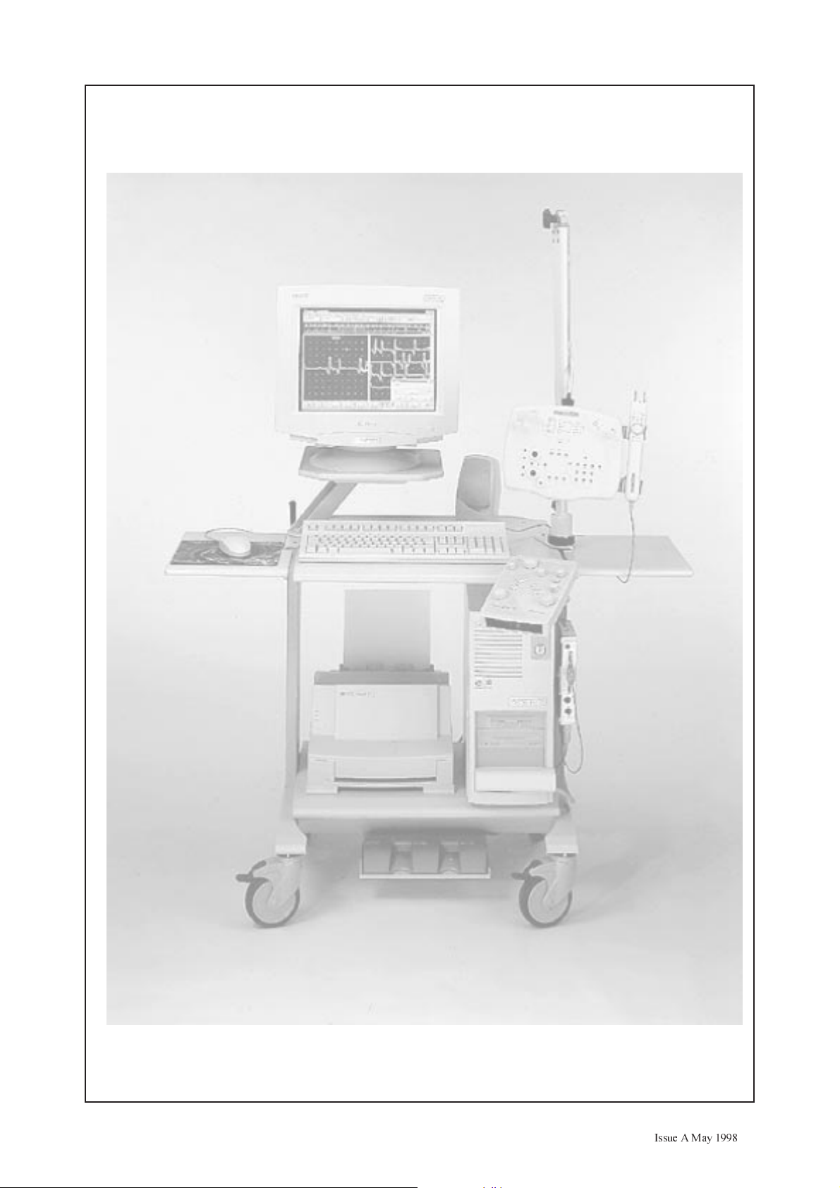
The Synergy Mobile EMG system is mounted on
a trolley and is based around a Pentium PC tower,
running under Windows 95. The system
incorporates the latest advances in technology for
transportable neurodiagnostic systems.
Synergy Mobile can have its own neurodiagnostic
applications software running at the same time as
other applications, as Windows 95 allows true
multitasking. However, performance may be
affected according to the system configuration e.g.
the amount of memory installed, processor speed
etc. so it is essential that the system is configured
according to the users requirements.
The equipment is operated through a dedicated
control panel or through the GUI (Graphical User
Interface) using a pointing device (e.g. mouse) to
access various screen “buttons”.
The Synergy Mobile uses an external high
resolution colour monitor.
The system can have two, five or ten amplifier
channels for monitoring patient signals. An
external loudspeaker is provided to listen to the
patient signals. Headphones can be connected if
required to monitor these signals.
EMG Stimuli to the patient can be delivered via a
maximum of two electrical stimulators. These can
be a single internal stimulator, which is contained
in the control unit and an external hand held
stimulator probe, or alternatively two probes. Each
hand held stimulator probe has its own controls
for setting the stimulus intensity, duration, polarity
and controlling acquisition.
An optional EP Stimulator providing audiological
stimuli to headphones and visual stimuli to an
external monitor can also be installed. Outputs are
also provided for supplying external visual
stimulators such as LED goggles or a flash head.
Hard copies of patient data can be recorded on an
external printer. The type of printer used is only
limited by the range available to Windows 95.
Patient data can be stored on floppy disks via the
internal floppy drive or on the internal hard disk.
An internal CD-ROM drive is fitted as standard to
allow other Windows 95 based software packages
to be installed.
Communication with other systems can be made
via an optional network card or modem to allow
transfer of patient data between systems.
Each system comes complete with the following
items.
¨
PC tower with full PC keyboard
¨
Isolation transformer/ Power supply
¨
Control unit includes internal EMG stimulator
¨
Connection box
¨
2, 5 or 10 channel Headbox
¨
Single or triple footswitch (optional)
¨
Pointing device (mouse)
A variety of applications software packages are
available for installation in the Synergy Mobile
which will enable the user to perform their
required clinical tests (see chapter 10). These can
either be installed with the system when purchased
or bought as an “add-on” at a later date.
Throughout this manual, the “pointing device”
will be assumed to be a mouse. If using another
device, read “other device” for “mouse”.
When instructed to “click” on a button, this
means move the pointer to the “button” icon
referred to on the screen, and then press the
left hand mouse button.
A knowledge of Windows 95 is essential in order
to be able to use the Synergy Mobile system. This
information can be obtained from your Windows
95 documentation, and from the many help
screens available from within Windows 95. To
call up the Windows 95 help screen menu once
INTRODUCTION ISSUE A March 1998
Synergy Mobile Workshop Manual Chapter 1 Page 1
INTRODUCTION
The Synergy Mobile EMG system is mounted on
a trolley and is based around a Pentium PC tower,
running under Windows 95. The system
incorporates the latest advances in technology for
transportable neurodiagnostic systems.
Synergy Mobile can have its own neurodiagnostic
applications software running at the same time as
other applications, as Windows 95 allows true
multitasking. However, performance may be
affected according to the system configuration e.g.
the amount of memory installed, processor speed
etc. so it is essential that the system is configured
according to the users requirements.
The equipment is operated through a dedicated
control panel or through the GUI (Graphical User
Interface) using a pointing device (e.g. mouse) to
access various screen “buttons”.
The Synergy Mobile uses an external high
resolution colour monitor.
The system can have two, five or ten amplifier
channels for monitoring patient signals. An
external loudspeaker is provided to listen to the
patient signals. Headphones can be connected if
required to monitor these signals.
EMG Stimuli to the patient can be delivered via a
maximum of two electrical stimulators. These can
be a single internal stimulator, which is contained
in the control unit and an external hand held
stimulator probe, or alternatively two probes. Each
hand held stimulator probe has its own controls
for setting the stimulus intensity, duration, polarity
and controlling acquisition.
An optional EP Stimulator providing audiological
stimuli to headphones and visual stimuli to an
external monitor can also be installed. Outputs are
also provided for supplying external visual
stimulators such as LED goggles or a flash head.
Hard copies of patient data can be recorded on an
external printer. The type of printer used is only
limited by the range available to Windows 95.
Patient data can be stored on floppy disks via the
internal floppy drive or on the internal hard disk.
An internal CD-ROM drive is fitted as standard to
allow other Windows 95 based software packages
to be installed.
Communication with other systems can be made
via an optional network card or modem to allow
transfer of patient data between systems.
Each system comes complete with the following
items.
¨
PC tower with full PC keyboard
¨
Isolation transformer/ Power supply
¨
Control unit includes internal EMG stimulator
¨
Connection box
¨
2, 5 or 10 channel Headbox
¨
Single or triple footswitch (optional)
¨
Pointing device (mouse)
A variety of applications software packages are
available for installation in the Synergy Mobile
which will enable the user to perform their
required clinical tests (see chapter 10). These can
either be installed with the system when purchased
or bought as an “add-on” at a later date.
Throughout this manual, the “pointing device”
will be assumed to be a mouse. If using another
device, read “other device” for “mouse”.
When instructed to “click” on a button, this
means move the pointer to the “button” icon
referred to on the screen, and then press the
left hand mouse button.
A knowledge of Windows 95 is essential in order
to be able to use the Synergy Mobile system. This
information can be obtained from your Windows
95 documentation, and from the many help
screens available from within Windows 95. To
call up the Windows 95 help screen menu once