manuals.online logo
Brands
  1. Home
  2. •
  3. Brands
  4. •
  5. Toshiba
  6. •
  7. Microwave Oven
  8. •
  9. Toshiba ER-1010ETE User manual

Toshiba ER-1010ETE User manual

SERVICE
DATA
FILE
NO.330-239
MICROWAVE
OVEN
ER-1010ET
SPECIFICATIONS
Power
Source
Voltage
220
Volts
Single
Phase
Usable
Volume
28
2
15
minutes
Safety
Interlock
Net
Weight
(with
Tray}
Two
switches
operated
by
door
handle
29
kg
Frequency
50
Hz
Power
Consumption
1.9
kW
(Approx.)
Output
1000W/200W
(DEFROST)
Microwave
Frequency
|
2,450
MHz
Magnetron
Type
2M137
|
Height.
370
mm
Outer
Width
570
mm
|
|
|
i
Depth
420
mm
|
Dimension
Height
224
mm
Inner
Width
—
350
mm
(Cavity)
Depth
360
mm
|
|
Specifications
are
subject
to
change
without
notice
Sep.
1984
Printed
in
Japan
GO
ER-1010ETE
|
CAUTION
This
device
is
to
be
serviced
only
by
properly
qualified
service
personnel.
Consult
the
service
data
for
proper
service
procedures
to
assure
continued
safety
operation
and
for
precautions
to
be
taken
to
avoid
possible
exposure
to
excessive
microwave
energy.
CAUTION
MICROWAVE
RADIATION
PERSONNEL
SHOULD
NOT
BE
EXPOSED
TO
THE
MICROWAVE
ENERGY
WHICH
MAY
RADI-
ATE
FROM
THE
MAGNETRON
OR
OTHER
MICROWAVE
GENERATING
DEVICE
IF
IT
IS
IMPROPERLY
USED
OR
CONNECTED.
ALL
INPUT
AND
OUTPUT
MICROWAVE
CONNEC-
TIONS,
WAVEGUIDES,
FLANGES,
AND
GASKETS
MUST
BE
SECURE.
NEVER
OPERATE
THE
DEVICE
WITHOUT
A
MICROWAVE:
ENERGY
ABSORBING
LOAD
ATTACHED.
NEVER
LOCK
INTO
AN
OPEN
WAVEGUIDE
OR
ANTENNA
WHILE
THE
DEVICE
IS
ENERGIZED.
PRECAUTIONS
TO
BE
OBSERVED
BEFORE
AND
DURING
SERVICING
TO
AVOID
POSSIBLE
EXPOSURE
TO
EXCESSIVE
MICROWAVE
ENERGY
(a)
Do
not
operate
or
allow
the
oven
to
be
operated
with
the
door
open.
(b)
Make
the
following
safety
checks
on
all
ovens
to
be
serviced
before
activiating
the
magnetron
or
other
microwave
source,
and
make
repairs
as
necessary:
(1)
Interlock
operation,
(2)
proper
door
closing,
(3)
seal
and
sealing
surfaces
(arcing,
wear,
and
other
damage),
(4)
damage
to
or
loosening
of
hinges
and
latches,
(5)
evidence
of
dropping
or
abuse.
(c)
Before
turning
on
microwave
power
for
any
service
test
or
inspection
within
the
microwave
generating
compartments,
check
the
magnetron,
or
transmission
line,
and
cavity
for
proper
alignment,
integrity,
and
connections.
(d)
Any
defective
or
misadjusted
components
in
the
interlock,
monitor,
door
seal,
and
microwave
genera-
tion
and
transmission
systems
shall
be
repaired,
replaced,
or
adjusted
by
procedures
described
in
this
service
data
before
the
oven
is
released
to
the
owner.
(e)
A
microwave
leakage
check
to
verify
compliance
with
the
performance
standard
should
be
performed
on
each
oven
prior
to
release
to
the
owner.
CONTENTS
PROPER
USE
AND
PRECAUTIONS
...........2cccece
cece
se
ceee
eee
cree
eeees
3
EST
CANAL
EWS
56
wdene
th
5
x
ba
oemad
SR
Sdc
Hee
tana
ted
ne
Joeman
3
PE
ATURES
okie
fee
heh
Quy
wba
bck
POE
Se
TD
RA
wan
ney
4
BERR
TION
cic
tosie-w
lore
tab
hh
Rohe
ore
aoe
aag
Sk
eee
vee
cae
d
aro
ae
eae.
4
INTERLOCK
MECHANISM
FUNCTIONS
AND
ADJUSTMENTS.........-.---
ek
patie
6
DISASSEMBLY
INSTRUCTIONS.........0
000
e
eee
cee
eee
ce
eeeeeeeeee
PEvae
roe
7
TROUBLE
SHOOTING
CHART
..........
0c
cece
ee
eee
eee
ees
Sais
na
tndioves
13
RN
AGRI
WENT:
mc
Sea
te
aon
oh
ead
deatst
dea
Decker
3
DES
ae
aan
tre
Ba
A
BE
18.
WIRING
DIRGRAME
is
ek
Hated
tlw
dened
td
ete
a
ute
een
ten
Pd
tara
te
may
SCHEMATIC
DIAGRAMS
ok
oondus
bib
acdeiats
dacnddawa
nek
s
Reed
wees
2
29
EXPLODED
VIEWS
AND
PARTSLISTS
......
00000
c
cece
cece
eee
beet
e
teens
4
|
ER-1010ETE
PROPER
USE
AND
PRECAUTIONS
1.
For
Safe
Operation
Damage
that
allows
the
microwave
energy
(that
cooks
or
heats
the
food)
to
escape
will
result
in
poor
cooking
and
may
Cause
serious
bodily
injury
to
the
operator.
IF
ANY
OF
THE
FOLLOWING
CONDITONS
EXIST,
OPERATOR
MUST
NOT
USE
THIS
APPLIANCE.
(Only
a
trained
serviceman
should
make
repairs.)
(1)
A
broken
door
hinge.
(2)
A
broken
door
mesh
plate.
(3)
A
broken
front
panel,
oven
cavity.
(4)
A
loosened
door
lock.
(5)
A
broken
door
lock.
The
door
gasket
plate
and,
oven
cavity
surface
should
be
kept
clean.
No
grease,
soil
or
spatter
should
be
allowed
to
build
up
on
these
surfaces
or
inside
the
oven.
DO NO
ATTEMPT
TO
OPERATE
THIS
APPLIANCE
WITH
THE
DOOR
OPEN.
The
microwave
oven
has
con-
cealed
switches
to
make
sure
the
power
is
turned
off
when
the
door
is
opened.
Do
not
attempt
to
defeat
them.
DO
NOT
ATTEMPT
TO
SERVICE
THIS
APPLIANCE
UNTIL
YOU
HAVE
READ
THIS
SERVICE
MANUAL.
2.
Correct
Installation
(1)
This
microwave
Oven
weights
29
kg
and
must
be
placed
on
a
horizontal
base
strong
enough
to
support
this
weight.
(2)
The
Oven
should
be
placed
as
far
from
high
tempera-
ture
heat
source
and
vapour
as
possible.
(3)
The
power
supply
cord
is
1.8
m_
long.
Grounding
is
required
when
connecting
the
power
source.
(4)
Power
consumption
of
this
oven
is
approximately
2.0
kW.
It
is
suggested
that
the
unit
is
operated
on
such
power
line
that
can
provide
more
power
than
this
rating.
Objects
must
not
be
placed
on
the
top
enclosure
so
as
not
to
obstruct
air
flow
for
ventilation.
~_
(o3)
~~
EXTERNAL
VIEWS
370
mm
:
t—
26
mm
227
mm
420
mm
oe
570
mm
Fig.
1
Front
View
37
mm
Fig.
2
Right
Side
View
|
2
ER-1010ETE
|
w
=>Seenous
=
=
-
DOOR
HANDLE
Employs
Automatic
Door
Latch
Mechanism.
OVEN
WINDOW
STIRRER
FAN
Operates
whenever
the
oven
is
in
use,
and
gives
even
dis-
tribution
of
Microwaves
throughout
the
cooking
cavity.
.
COOKING
TRAY
DISPLAY
WINDOW
POWER
LEVEL
PAD
TIMER
KNOB
NUMBER
PAD
START
PAD
CLEAR
PAD
MEMORY
PAD
ZA
©
AN
jo
|
=a
©
o,
&
®
*
ee
HUG
a
2,
|
=
S
a)
Fig.
3
OPERATION
.
Open
the
door
by
pulling
out
on
handle,
the
oven
light
will
turn
on.
Place
the
food
on
the
cooking
tray.
.
Close
the
door,
the
oven
light
will
turn
off,
and
the
latch
will
snap
shut
automatically
locking
the
door.
If
the
door
is
not
closed
properly,
the
oven
will
not
start.
.
Set
the
power
level
simply
by
touching
the
FULL
pad
or
the
DEFROST
pad
.
Either
of
dots,
below
the
mark
tS
(FULL)
or
above
the
mark
%
(DEFROST),
will
light
up.
.
Set
the
timer,
simply
by
turning
the
timer
knob,
to
the
desired
cooking
time;
up
to
15
min.
when
FULL
setting,
or
up
to
30
min.
when
DEFROST
setting.
The
setting
time
will
appear
in
the
display
window.
NOTE:
It
can
be
set
the
cooking
time with
the
in-
crement
as
shown
in
the
next
table.
.
Touch
the
START
pad
[@]
,
to
start
the
cooking
process.
The
dot
above
.the
mark
<<
(COOK)
will
light
up
and
the
oven
light
and
fan
will
turn
on.
They
operate
during
cooking.
6.
The
cooling
will
be
continued
until;
the
timer
returns
to
‘0’.
The
oven
will
automati-
cally
shut
off
and
notice
it
by
three
beeps.
The
oven
light,
fan
and
all
indication
in
the
display
window
will
turn
off.
the
CLEAR
pad
is
touched.
The
oven
will
automatically
shut
off,
and
the
oven
light,
fan
and
all
indication
in
the
display
window
will
turn
off.
the
door
is
opened
during
cooking.
The
oven
will
automatically
shut
off,
and
the
fan
will
turn
off.
In
the
display
window,the
COOK
dot
will!
turn
off
and
the
FULL
or
DEFROST
dot
and
the
time
will
remain.
To
disappear
them,
touch
the
CLEAR
pad
The
oven
will
not
restart
until
the
door
is
closed
and
the
START
pad
is
touched
again.
FULL
POWER
SETTING
fiete
2min
|
over
2min.
upto
5min.
30
sec.
over
5
min.
30
sec.
30
sec.
up
to
10
min.
over
10
min.
1
mi
up
to
15
min.
mu:
DEFROST
POWER
SETTING
over
2
min.
upto
5
min.
over
5
min.
up
to
10
min.
over
10min.
up
to
16
min.
Example
of
Setting
WMS
La)
Touch
pad.
i,
®D
,
Ssh
Ww
Set
Timer
to
sg
4
min.
30
sec.
Lt:
0
vi,
D
Touch
‘HM
pad.
=
tte
Ws
fn
i,
7)
Open
the
door
during
cooking.
a
eM
9
felsuy
ey
’
ER-1010ETE
|
ensovere
|
4
j
MEMORY
This
oven
employs
the
memory
function
which
is
available
to
enter
7
kinds
of
the
cooking
processes,
using
with
the
MEMORY
pad
and
one
of
the
NUMBER
pads
<—
This
is
convenient
tor
the
repeatable
cooking.
TO
SET
MEMORY
with
an
example;
1.
Touch
FULL
pad
2.
Set
the
timer
to
1
min.
30
sec.
3.
Touch
the
NUMBER
pad
[_1
|
A
dot
on
the
corner
in
the
number
pad
will
light
up.
4.
Touch
MEMORY
pad
The
cooking
process
with
FULL
power
for
1
min.
30
sec.
was
entered
into
the
NUMBER
pad
[
1]
.
The
other
cooking
processes
can
be
memorized
into
the
each
NUM-
BER
pad
with
the
same
steps.
TO
USE
MEMORY
1.
Touch
the
NUMBER
pad
[1
|
A
dot
in
the
number
pad
["1]
will
light
up
and
the
memorized
cooking
process,
the
power
level
and
the
cooking
time,
will
appear
in
the
display
window.
2.
Touch
the
START
pad
The
oven
will
start
the
cooking
process
which
is
mem-
orized.
TO
CHANGE
MEMORY
The
memory
cannot
be
cleared
or
changed
even
by
touch-
ing
the
CLEAR
pad
[0]
,
except
when
the
new
cooking
process
with
the
same
steps
in
‘TO
SET
MEMORY’
is
entered,
1.
Set
the
power
level.
2.
Set
the
cooking
time.
3.
Touch
the
NUMBER
pad
in
which
the
memory
is
to
be
changed.
4.
Touch
MEMORY
pad.
NOTE:
The
area
beside
each
NUMBER
pad
may
be
served
to
put
on
the
paper
for
your
quick
reference
of
the
mem-
ory.
ER-1010ETE
|
INTERLOCK
MECHANISM
FUNCTIONS
AND
ADJUSTMENTS
The
door
lock
mechanism
is
a
device
which
has
been
specially
designed
to
completely
eliminate
microwave
radia-
tion
when
the
door
is
opened
during
cooking,
and
thus
to
perfectly
prevent
the
danger
resulting
from
the
leakege
of
microwave.
Whenever
the
door
lock
mechanism
is
repaired,
check
microwave
leakage
according
to
the
procedure
specified
in
page
19.
1.
Mechanical
Function
When
the
door
is
closed,
the
catch
under
the
door
handle
snaps
on
the
latch
on
the
oven,
locking
the
oven
door.
If
the
door
is
not
closed
properly,
the
oven
will
not
operate.
Fig.
4
shows
the
closed
door
condition.
When
the
door
is
closed,
the
lower
catch
pushed
the
slider
of
the
interlock
monitor
switch
to
bring
it
“OFF”
condi-
tion,
then
the
catches,
upper
and
lower,
individually
engage
with
the
latch
and
the
tip
of
the
catches
pushes
the
lever
which
presses
the
button
of
the
primary/secondary
interlock
switch
to
bring
them
under
“ON”
condition.
Latch
Primary
Interlock
Switch
Catch
Interlock
Monitor
Switch
Latch
Spring
Slider
Hook
Spring
Secondary
Lever
Interlock
Switch
Fig.
4
When
the
handle
is
pulled
to
open
the
door,
as
illustrated
in
Fig.
5,
the
catches
disengage
from
the
latch,
leaving
the
lever
in
a
free
state,
thus
the
lever
is
pushed
by
the
switch
button
to
turn
off
the
switch
and
open
the
circuit.
Then
the
lower
catch
releases
the
slider
to
bring
the
interlock
Monitor
switch
under
“ON”
condition.
Primary
Latch
Interlock
\
Switch
Interlock
Monitor
Switch
Latch
Spring
Slider
Hook
op
ung
Secondary
Lever
Interlock
Switch
Fig.
5
2.
Adjustment
Procedure
(1)
Preliminaries:
The
primary
and
secondary
interlock
switch
position
should
be
adjusted
such
that
the
switches
become
“ON”
condition
where
the
lever
is
lowered
by
4mm
measured
at
the
tip
of
the
lever.
(Refer
to
Fig.
6)
ON
4mm
Fig.
6
(2)
Adjustment
steps:
a}
Loosen
two
mounting
screws.
b)
Adjust
the
primary/secondary
interlock
switch
assembly
position.
c)
Confirm
the
movement
described
in
(1).
d)
Tighten
the
two
mounting
screws.
|
ER-1010ETE
DISASSEMBLY
INSTRUCTIONS
1.
Cabinet
and
Back
Cover
Removal
(Refer
to
Fig.
7):
(1)
Remove
nine
screws
‘1’
to
‘7’
on
the
back
and
‘8’
to
‘9’
on
the
side
of
the
cabinet.
(2)
(The
screws
with
washer
are
located
‘2’
to
‘6’.)
(3)
Remove
the
cabinet.
(4)
Remove
four
screws
‘10’
to
‘13’.
(5)
Remove
the
back
cover.
13
Fig.
7
2.
Oven
Assembly
Removal
(Refer
to
Fig.
8)
Fig.
8
(1)
Remove
the
cabinet
parts.
(2)
Remove
three
screws
‘1’
at
bottom
of
the
oven
front,
anda
screw
‘2’
on
the
back
of
oven.
(3)
Disconnect
the
connector
‘B’
and
two
leads
of
HV
transformer
‘3’
from
the
magnetron
‘4’,
(4)
Remove
the
oven
assembly.
3.
Magnetron
Removal
(Refer
to
Fig.
8)
(1)
Remove
the
oven
assembly.
(2)
Remove
a
screw
‘5’
which
secure
the
duct
‘6’,
and
remove
it.
(3)
Remove
three
screws
‘7’
which
secure
the
blower
‘8’,
and
remove
it.
(4)
Remove
four
nuts
‘9’.
(5)
Remove
the
magnetron
‘4’.
:=R-1010ETE
|
CAUTION-MICROWAVE
LEAKAGE
Never
install
the
magnetron
without
the
metallic
gasket
plate
which
is
packed
with
each
magnetron
to
prevent
microwave
leakage.
(Refer
to
Fig.
9
and
10)
Whenever
repair
work
is
carried
out
on
magnetron,
check
the
microwave
leakage
according
to
the
procedure
specified
in
the
“Microwave
Leakage
Test’’
on
page
20.
**
*
*
DO
NOT
OPERATE
WITHOUT
*
*
* *
CABINET
v
Metallic
Gasket
Plate
Magnetron
Antenna
CAUTION:
The
connection
of
HV
Leads
of
the
capacitor
must
be
as
Fig.
9
shown
in
Fig,
12.
Magnetron
Antenna
Wave
Guide
(ACO
Metallic
Gasket
Plate
Fig.
10
.
To
HV
Relay
~
4.
HV
Transformer
Removal
(Refer
to
Fig.
11)
To
(1)
Remove
the
cabinet
parts
and
the
oven
assembly.
Be
elsy
a“
*
(2)
Remove
four
screws
‘1’
which
secure
the
plate
‘2’.
.
(3)
Remove
the
plate
‘2’.
oe
Magnetron
(4)
Remove
four
screws
‘3’.
(5)
Remove
the
HV
transformer
‘4’.
To
HV
Transformer
Fig.
12
(1)
(2)
(3)
(4)
(1)
(2)
{3)
(4)
Control
Panel
Assembly
Removal
(Refer
to
Fig.
13)
Remove
the
cabinet
parts.
Disconnect
the
Connector
‘A’.
Remove
two
screws
‘1’.
Remove
the
contro!
panel
assembly.
Fig.
13
Door
Assembly
Removal
(Refer
to
Fig.
14)
Remove
the
cabinet
parts.
Remove
two
screws
‘1’
at
top
door
hinge.
Remove
two
screws
‘2’
at
bottom
door
hinge.
Remove
the
door
assembly.
-.—
1
aa
a.
Fig.
14
7.
Outer
Screen
Barrier
Removal
(Refer
to
Fig.
15)
(1)
Remove
the
cabinet
parts
and
the
door
assembly.
|
ER-1010ETE
(2)
Remove
ten
screws
‘1’
which
secure
the
door
choke
plate
‘2’.
(3)
Remove
the
door
choke
plate
‘2’,
the
inner
screen
barrier
‘3’
and
the
screen
‘4’.
(4)
Remove
the
door
cover
‘5’.
(5)
Remove
six
screws
‘6’
which
secure
the
door
sash
‘T’.
(6)
Remove
the
door
sash
‘7’.
(7)
Remove
three
screws
‘8’
which
secure
the
mount
plate
‘9’,
and
remove
it.
(8)
Remove
four
screws
‘10’
which
secure
the
upper
hinge
unit
‘11’
and
lower
hinge
unit
‘12’,
and
remove
them.
(9)
Remove
the
door
handle
‘13’.
(10)
Remove
the
outer
screen
barrier
‘14’.
8.
Caution
WHENEVER
ANY
OVEN
DOOR
PARTS
ARE
REPAIRED
OR
REPLACED/CHECK
MICROWAVE
LEAKAGE.
(Refer
to
Fig.
16)
(1)
(2)
(3)
(4)
(5)
Prepare
a
piece
of
paper
and
cut
it
approx.
25mm
(1”)
wide
by
100mm
(4")
long.
Open
the
door
and
put
it
on
the
oven
front
plate.
Close
the
door
to
hold
it
between
the
door
gasket
plate
and
the
oven
front.
Draw
out
the
paper.
If
it
is
not
drawn
smoothly,
the
door
gasket
plate
is
working
properly.
Repeat
above
procedure
at
other
several
position
to
check
for
possible
gap
around
the
door.
But
if
any
gap
are
found,
adjust
the
position
of
the
hinge
or
the
latch
position
of
secondary
interlock
according
to
the
steps
described
on
item
9,
“Hinge
and
Latch
Position
Adjustment”’.
NOTE:
Smal!
gap
may
be
acceptable
if
the
microwave
leakage
does
not
exceed
1
mw/cm?.
Fig.
16
Hinge
and
Latch
Position
Adjustment
(Method
to
reduce
the
gap
between
the
gasket
plate
and
the
oven
front)
(1)
To
reduce
the
gap
located
on
part
“A’’.
(See
Fig.
17)
a)
Loosen
two
screws
on
bottom
hinge,
then
push
the
door
to
contact
the
gasket
plate
to
oven
front.
b)
Tighten
two
screws.
c)
Check
the
gap
(2)
To
reduce
the
gap
located
on
part
‘‘B’’.
(See
Fig.
17)
a)
Loosen
two
screws
on
top
hinge,
then
push
the
door
to
contact
the
gasket
plate
to
oven
front.
b)
Tighten
two
screws.
c)
Check
the
gap
|
ER-1010ETE
Fig.
17
(3)
To
reduce
the
gap
located
on
part
‘’C’’
and
“D’’.
(See
a
bs
aes
Fig.
17)
a)
Loosen
three
screws
on
tatch
located
right
of
oven
body.
(Fig.
18)
b)
Draw
the
latch
inward
slightly.
c)
Tighten
two
screws.
d)
Check
the
gap
Catch
Fig.
18
=R-1010ETE
|
10.
Control
Panel
Parts
Removal
10.1
Control
Panel
Assembly
Removal
(Refer
to
Fig.
20)
1)
Remove
the
cabinet
parts.
2)
Disonnect
three
connectors,
T1,
T2;
and
T3.
(Refer
to
Fig.
20)
3)
Remove
two
screws
‘1’
holding
the
panel
assembly
to
the
oven
front.
4)
Pull
out
the
panel
assembly
from
the
oven
front.
10.2
Key
Board
Assembly
Removal
(Refer
to
Fig.
20)
1)
Remove
the
pane!
assembly.
2)
Remove
four
screws
‘2’
holding
the
Key
Board
As-
sembly
‘5’
to
the
panel
sash
‘4’,
3)
Pull
Key
Board
Assembly
‘5’.
10.3
EDT-1010
Board
Assembly
Removal
1)
Remove
the
panel
assembly.
2)
Remove
two
screws
‘3’
holding
the
LED
‘7’
to
the
Fig.
20
Key
Board
Assembly
’5’.
3)
Disconnect
the
connector,
T4,
T5
and
T6,
from
EDT-1010
Board
Assembly.
4)
Remove
EDT-1010
Board
Assembly
‘6’
by
pushing
the
latch
of
supports.
LED
EDT-1010
Board
Assembly
waePush
Support~~—
Panel
Chassis
Fig.
21
Low
Voltage
DC
Relay
DC
Relay
Transformer
(2) (1)
Fig.
19
—12—
|
ER-1010ETE
TROUBLESHOOTING
CHART
DANGER
OF
HIGH
VOLTAGE
4000
volts
exist
at
the
high
voltage
area.
Do
not
operate
the
oven
with
the
cabinet
parts
removed.
Do
not
remove
the
cabinet
parts
unless
the
power
cord
is
unplugged
from
wall
outlet.
Determine
whether
or
not
a
defect
is
in
the
control
panel
block
or
others
first.
The
control
panel
assembly
is
divided
into
five
units,
key
board
assembly,
timer,
two
of
LED
board
assemblies
and
EDT-1010
board
assembly.
When
they
are
judged
to
be
defect
according
to
following
troubleshooting
charts,
they
should
be
replaced
by
unit.
Do
not
check,
repair,
or
adjust
the
control
panel
block
unless
the
power
cord
is
unplugged
from
wall
outlet.
’
1.
Troubleshooting
by
unit
replacement
according
to
the
symptoms
indicated
1.1
Key
Board
Assembly
The
following
symptoms
indicate
a
defective
key
board
assembly.
Replace
the
key
board
assembly.
1)
When
touching
the
pads,
a
certain
pad
produces
no
signal
at
all.
2)
When
touching
a
pad,
two
figures
or
more
are
dis-
played.
3)
When
touching
the
pads,
sometimes
a
pad
produces
no
signal.
4)
Only
one
indicator
does
not
light
up.
(In
connection
with
EDT-1010
board
assembly).
1.2
LED
Indicator
Board
Assemblies
The
following
symptoms
indicate
a
defective
LED
indicator
board
assembly.
Replace
the
LED
indicator
board
as-
sembly.
1)
A
certain
digit,
and/or
some
segments
do
not
light
up.
2)
At
a
certain
digit,
brightness
is
low
when
it
lights
up.
(In
connection
with
EDT-1010
board
assembly
and
timer)
1.3.
EDT-1010
Board
Assembly
The
following
symptoms
indicate
a
defective
EDT-1010
board
assembly.
Replace
the
EDT-1010
board
assembly.
1)
In
connection
with
key
board
assembly.
a)
When
touching
the
pads,
a
certain
group
of
pads
do
not
produce
the
signal.
b)
When
touching
the
pads,
no
pads
produce
the
signal.
2)
in
connection
with
LED
indicator
board
assembly.
a)
The
corresponding
segments
of
all
digits
do
not
light
up,
or
they
continue
to
light
up.
b)
Wrong
figure
appears.
c)
The
figures
of
all
digits
flicker.
3)
Other
possible
troubles.
a)
Buzzer
does
not
sound
or
sounds
continuously.
(Note:
During
pushgin
CLEAR
pad
[©
]
,
buz-
zer
will
sound
continuously.)
1.4
Timer
The
following
symptoms
indicate
a
defective
timer.
Replace
the
timer.
1)
In
connection
with
LED
indicator
assemblies.
a)
When
turning
the
timer
knob,
only
a
certine
time
is
indicated.
b)
When
setting
the
timer
knob
to
the
maximum
set-
ting,
any
indication
other
than
the
following
is
displayed;
at
FULL
power
setting
:
15
:
00
at
DEFROST
power
setting
:
30
:
00
ag3—
-R-1010ETE
2.
Main
Fuse
is
blown
out
Plug
the
power
cord
into
wali
outlet.
No
Open
the
door.
No
Is
fuse
blown
Yes
out?
Set
the
cooking
time.
Close
the
door
and
push
the
START
pad
&
Replace
EDT-1010
board
assembly.
1)
Layer
short
on
the
secondary
winding.
HV
Transformer
2)
Poor
insulation
between
capaci-
tor
terminals.
HV
Capacitor
Door
:
Close
Is
fuse
blown
Yes
out?
No
Is
interlock
monitor
switch
closed?
Yes
Open
the
door.
Replace
interlock
monitor
switch.
No
Is
secondary
interlock
switch
closed?
Replace
secondary
interlock
switch
and
interlock
monitor
switch.
Replace
secondary
interlock
switch
and
interiock
monitor
switch.
Replace
interlock
monitor
switch.
No
\s
fuse
blown
Yes
out?
Check
the
parts
listed
in
Table
1.
Check
for
continuity
between
these
portions.
yi
High
Voltage
Capacitor.
Fig.
22
Table
1
Diagnosis
The
fuse
does
not
blow
right
away,
but
it
blows
in
a
few|
Replace
HV
trans-
seconds,
then
there
is
a
layer
short.
former
Check
for
the
continuity
between
capacitor
terminals.
there
is
continuity,
capacitor
is
defective.
(See
Fig.
22)
{f|
Replace
HV
capaci-
ee
fe
3.
Magnetron
does
not
operate
(Food
will
not
become
hot)
Plug
the
power
cord
into
wail
outlet.
Set
the
power
level
IsFULLCS
or
DEFROST
,%,
light
on?
Set
the
cooking
time.
Close
the
door
and
push
the
START
pad
&
ts
fuse
(0.2A)
blown
out?
Normal
Check
power
transformer.
Defective
Replace
EDT-1010
board
assembly.
Yes
id
soor
opening
monitor
switch
is
opened?
fillustrated
in
Fig.
23,
Check
/replace
door
opening
monitor
switch.
Close
the
door
and
push
the
START
pad
<>.
Note:
Check
wire
harness
and
wiring
Check
the
voltage
betwee
i
I
I
|
|
|
|
|
|
|
|
before
replacing
the
switch
|
|
|
|
|
|
|
L
in
Fig.
23.
{
AC220V
|
!
|
I
——»|
°
I
|
I
Check
the
parts
listed
!
|
in
Table
3
!
!
|
AC
AC
AC
|_7v
7V_32v
|
Normal
Power
Transformer
im
=
AC220V
el
see
ame
lA
Disconnect
these
quick
connectors.
H.V.
Transformer
Disconnect
quick
connectors
quick
connectors
as
illustrated
Check
the
parts
listed
Replace
EDT-1010
board
assembly
'ER-1010ETE
Note:
Check
by
sound
of
blower
motor.
R-1010ETE
|
Cause
Table
2
Diagnosis
Remedy
Parts
Magnetron
1)
Open
magnetron
heater.
Check
continuity
of
magnetron
heater
with
wires
removed
using
multimeter.
!f
there
is
no
continuity,
magnetron
heater
is
open.
Replace
magnetron.
2)
Shorted
magnetron
Connect
megger
leads
to
magnetron
terminals
and
magnetron
body.
If
there
is
contiuity,
magnetron
is
defective.
(In
this
event.
main
fuse
will
be
blown.)
Replace
magnetron.
Rectifier
Defective
rectifier
Check
continuity
of
recrifier
in
forward
and
backward
di-
rection
with
DC
megger.
If
there
is
continuity
in
backward
direction,
rectifier
is
defective.
(In
this
event,
high-voltage
capacitor
will
be
come
hot.)
Replace
rectifier.
H.V
transformer
Open
coil
of
H.V.
transformer
Check
primary
coil
and
secondary
coil
for
continuity.
If
there
is
no
continuity,
transformer
is
defective.
Replace
H.V.
transformer.
H.V.
capacitor
Secondary
interlock
switch
Primary
interlock
switch
|
Shorted
H.V.
capacitor
Poor
contact
of
secondary
interlock
switch
Poor
contact
of
primary
interlock
switch
DC
relay
(2)
|Defective
DC
relay
(2
Relay
(3)
Magnetron
thermostat
or
oven
thermostat
Defective
relay
(3)
1)
Magnetron
thermostat
open.
2)
Oven
thermostat
open.
Check
continuity
of
capacitor
terminals
with
wires
removed.
lf
there
is
continuity,
capacitor
is
defective.
If
capacitor
shorts,
fuse
is
blown
out.
Table
3
Diagnosis
Check
the
terminals
for
continuity
with
wires
removed
using
multimeter,
pressing
switch
ON
and
OFF
repeatedly.
Check
relay
terminals
for
continuity
with
wires
removed
and
energizing
DC
relay
coil.
If
there
is
no
continuity
between
terminals,
DC
relay
is
defective.
Check
realy
terminals
for
continuity
with
wires
removed
and
energizing
relay
coil.
Sf
there
is
no
continuity
between
terminals,
relay
is
defective.
Check
thermostat
terminals
for
continuity
with
wires
re-
moved
using
multimeter.
If
there
is
no
continuity
between
terminals,
thermostat
is
defective.
—~16—
Replace
H.V.
capacitor.
Replace
or
adjust.
Replace
DC
relay
(?).
Replace
relay
(3).
Replace
thermostat.
4.
Others
Trouble
Cause
Table
4
Diagnosis
|
ER-1010ETE
Oven
lamp
does
not
illuminate,
when
door
is
open.
ee
1)
Fuse
blown
out.
Check
fuse
in
fuse
holder.
Replace
fuse.
—
2)
Poor
contact
of
power
cord.
Check
power
cord
for
continuity.
Also
check
to
see
if
power
leads
are
securely
wired.
Adjust
or
replace
3)
Lamp
blown
out.
Check
famp.
Replace
lamp.
4)
Magnetron
thermostat
open.
b
5)
Oven
thermostat
open.
Lamp
does
not
illuminate,
even
after
lamp
is
replaced
when
door
is
open.
Check
thermostat
terminals
for
continuity
with
wires
removed
using
multimeter.
If
there
is
no
continuity
between
terminals,
thermostat
is
defective.
Replace
thermostat.
6)
Defective
lamp
contro!
switch
Check
wiring
on
each
terminal,
NO,
NC
and
COM.
\f
it
is
correct,
check
terminals
for
continuity
with
wire
removed
using
multimeter,
pressing
switch
ON
and
OFF
repeatedly.
Replace
lamp
control
switch
Stirrer
fan
does
not
rotate,
Sparking
(or
arcing
in
cavity).
t
L
1)
Defective
stirrer
Motor
if
motor
does
not
operate
with
240V
applied
to
motor
terminals,
motor
may
be
faulty.
Replace
stirrer
2)
Stirrer
fan
caught
by
cavity
or
spatter
shield
1)
Carbonized
dust
in
oven.
2)
Stirrer
fan
touches
cavity
Check
fan
movement.
Check
whether
dust
accumulates
on
spatter
shield
or
its
support.
Check
fan
movement.
Clean
oven
cavity.
Microwave
turns
off
during
cook-
ing
cycle.
Only
regular
output.
1)
Too
smal!
load
of
food.
If
small
amount
of
food
is
heated
for
a
long
time,
micro-
wave
is
turned
off
during
operation.
To
increase
load,
place
a
cup
of
water
into
oven
cavity
in
addition
to
food
to
2)
Defective
magnetron
thermostat
1)
Defective
DC
relay
(1)
2)
Defective
HV
relay.
Check
relay
terminals
for
continuity
with
wires
removed
and
energizing
DC
relay
coil.
If
there
is
no
continuity
between
terminats,
DC
relay
is
defective.
Check
relay
terminals
for
continuity
with
wires
removed
and
energizing
HV
relay
coil.
if
there
is
no
continuity
between
terminals,
HV
reiay
is
defective.
CAUTION:
HV
wire
must
be
removed
before
check.
In
this
case,
oven
lamp
does
not
illuminate
but
blower
operates
normally.
SATS
Replace
thermostat.
Replace
DC
relay
(1).
Replace
HV
relay.
R-1010ETE
|
MEASUREMENT
1.
Microwave
Output
Power
1.1.
standard
Method
Microwave
output
power
can
be
checked
by
indirectly
Measuring
the
temperature
rise
of
a
certain
amount
of
water
exposed
to
the
microwave
as
directed
below.
Oven
should
be
run
for
pre-heating
about
30
minutes
be-
fore
measurement.
:
(1)
Prepare
2
glasses
or
plastic
breakers
or
similar
cups.
(2)
Pour
1
liter
of
cold
tap
water
(it’s
temperature
should
be
10
+
1°)
into
each
beaker.
(3)
Stir
the
water
with
a
thermometer
and
note
water
tem-
peratures,
T;
and
T,,
in
°C.
(4)
Put
both
beakers
in
place
on
the
tray
(it's
temperature
should
be
the
same
as
ambient).
(Fig.
24)
{5)
Heat
the
water
for
a
period
of
exactly
1
minute
30
seconds.
(6)
Take
both
beakers
out
of
the
oven,
stir
the
water
with
the
thermometer,
and
note
the
temperatures,
T,’
and
T2',in
°C.
(7)
Calculate
the
temperature
rise
of
the
water
in
each
beaker
by:
AT,
=T1'-T
(°C)
AT,
=T2'-T
(°C)
(8)
Obtain
the
microwave
output
power
by
the
following
formula
or
by
using
the
monograph
in
Fig.
20.
+
Power
=100x
Bi
Sle
5
(watts)
The
power
measured
should
be
1O000W
+
12.5%
CAUTION:
1.
Heating
time
should
be
exactly
1
seconds.
2.
Water
load
should
be
measured
exatctly
to
2
liters.
3.
Input
power
voltage
should
be
exactly
220
V
as
speci-
fied.
4.
Ambient
temperature
should
be
20
+
1°C.
Two
1,000
cc
Beakers
*
minute
and
30
Water
Load
Tray
Fig.
24
1.2
Alternative
Simplified
Method
1)
2)
3)
4)
—
18
—
Fill
a
glass
cup
with
200
milliliters
cold
tap
water.
Put
the
cup
into
the
oven.
Heat
for
about
3
minutes.
It
can
be
easily
confirmed
that
the
power
output
is
in
the
normal
level
if
the
water
in
the
cup
is
boiling.
1100
£
1000
oO
s
5
2
fo}
=
900
a
a
re)
ao
8
800
$
oO
3
s
700
7
8
9
10
11
2
Temperature
Rise
(°C)
Fig.
25
Monograph
of
Microwave
Output
Power
for
Water
Temperature
Rise
in
the
Oven
2.
Microwave
Heat
Distribution-Heat
Evenness.
The
microwave
heat
distribution
can
be
checked
by
indir-
ectly
measuring
the
water
temperature
rises
at
certain
po-
sition
in
the
oven
as
directed
below.
(1)
Prepare
five
beakers
made
of
‘Pyres’
and
having
100
cc
Capacity
each.
(2)
Measure
exactly
100cc
of
water
load
with
use
of
a
measuring
cylinder
and
pour
it
into
each
beaker.
(3)
Measure
the
temperature
of
each
water
load.
(The
readings
shall
be
taken
to
one
place
of
decimals.)
(4)
Put
each
beaker
in
place
on
the
cooking
tray
as
illus-
trated
in
Fig.
26
and
start
heating.
(5)
After
heating
2
minutes,
measure
the
temperatures
of
water
in
each
beaker.
(6)
Calculate
the
temperature
difference
for
each
water
load
to
get
the
heat
distrubution
rate
by
the
following
formula.
Minimum
temperature
rise
Maximum
temperature
rise
Heat
distribution
rate
=
x
100%
The
result
should
exceed
65
%.
Five
100
cc
Beakers
Front
End
Fig.
26
|
ER-1010ETE
|
3.
Electrical
Continuity
Check
of
Interlock
Switches
3.1
Procedure
NOTE:
Remove
the
power
plug
from
the
wall
receptacle
before
testing.
1.
Primary
Interlock
Switch
1)
Disconnect
two
connectors
from
primary
interlock
switch.
2)
Connect
the
ohmeter
leads
between
the
terminals
of
the
primary
interlock
switch.
3)
Read
the
value
of
resistance
between
the
termjnals
of
the
switch,
when
the
door
is
opened,
and
when
the
door,
is
closed.
2.
Secondary
Interlock
Switch
1)
Disconnect
two
connectors
from
secondary
inter-
lock
switch.
2)
Connect
the
ohmeter
leads
between
the
terminals
of
the
secondary
interlock
switch.
3)
Read
the
value
of
resistance
between
the
terminals
of
the
switch,
when
the
oven
door
is
opened,
and
when
the
oven
door
is
closed.
3.2
Judgement
The
value
of
resistance
should
be
applied
to
the
value
speci-
fied
below.
Push
Cook
Button
Primary
Interlock
Switch
Secondary
Interlock
Switch
Interlock
Monitor
Circuit
When
value
obtained
is
not
acceptable,
the
switches
should
be
replaced
or
adjusted
again.
—19—
3-1010ETE
|
4.
Microwave
Leakage
Test
4.1
Warning
(1)
DO
NOT
place
your
hands
into
any
suspected
micro-
wave
radiation
field
unless
the
safe
density
level
is
known.
(2)
Always
start
measuring
of
an
unknown
fieid
to
assure
safety
for
operating
personel
from
radiation.
(3)
Slowly
approach
the
unit
under
test
until
the
radio-
meter
reads
an
appreciable
radiation
leakage
from
the
unit
under
test.
(4)
Caré
should
be
taken
not
to
place
the
eyes
in
direct
line
with
the
source
of
microwave
energy.
4.2
Method
The
power
density
of
the
microwave
radiation
emitted
by
the
microwave
oven
should
not
exceed
1mW/cm?
at
any
point
50
mm
or
more
away
from
the
external
surface
of
the
oven
as
measured
prior
to
acquisition
by
a
purchaser
and
thereafter
once
the
oven
is
in
use,
5mW/cm?
at
any
point
50
mm
or
more
away
from
the
external
surface
of
the
oven.
Measurements
should
be
made
with
the
oven
operating
at
its
maximum
output
and
containing
a
load
of
275
+
15
mililiters
of
tap
water
initially
at
20
+
5°C
placed
within
the
cavity
at
the
center
of
the
load-carrying
surface
pro-
vided
by
the
manufacturer.
The
water
container
should
be
a
low
from
600
mililiters
beaker
having
an
inside
diameter
of
approximately
85mm
and
made
of
an
electrically
non-
conductive
material
such
as
glass
or
plastic.
4.3
Procedures
(1)
Prepare
600
cc
glass
or
plastic
container.
(2)
Pour
275+
15
mililiters
of
tap
water
initially
at
20
+
5°C
in
the
container.
(3)
Place
it
at
the
center
of
the
tray
and
set
it
in
a
cavity.
(4)
Operate
the
oven.
(5)
Measure
the
microwave
feakage
using
a
Narda
8100
or
similarly
approved
microwave
leakage
meter
after
a
few
minutes
operation.
—20—

Other Toshiba Microwave Oven manuals

Toshiba MM2-MM20PF(WH) User manual

Toshiba

Toshiba MM2-MM20PF(WH) User manual

Toshiba MWP-MM20P(BK) User manual

Toshiba

Toshiba MWP-MM20P(BK) User manual

Toshiba EM9P022XC User manual

Toshiba

Toshiba EM9P022XC User manual

Toshiba ML2-EC09SAIT User manual

Toshiba

Toshiba ML2-EC09SAIT User manual

Toshiba ML-EM34PF User manual

Toshiba

Toshiba ML-EM34PF User manual

Toshiba MW2-MG20PF User manual

Toshiba

Toshiba MW2-MG20PF User manual

Toshiba ML2-EC42SAE User manual

Toshiba

Toshiba ML2-EC42SAE User manual

Toshiba MM-EM25P(WH) User manual

Toshiba

Toshiba MM-EM25P(WH) User manual
Toshiba MV-AM20T(BK) User manual

Toshiba

Toshiba MV-AM20T(BK) User manual

Toshiba ML2-EC10SA(BS) User manual

Toshiba

Toshiba ML2-EC10SA(BS) User manual

Toshiba MW2-AG23PF User manual

Toshiba

Toshiba MW2-AG23PF User manual

Toshiba EM131A5C-SS User manual

Toshiba

Toshiba EM131A5C-SS User manual

Toshiba MW2-AC25TF(BK) User manual

Toshiba

Toshiba MW2-AC25TF(BK) User manual

Toshiba EC042A5C-SS User manual

Toshiba

Toshiba EC042A5C-SS User manual

Toshiba ML2-EM09PA(BS) User manual

Toshiba

Toshiba ML2-EM09PA(BS) User manual

Toshiba EC042A5C-BS User manual

Toshiba

Toshiba EC042A5C-BS User manual

Toshiba ML-EM62P User manual

Toshiba

Toshiba ML-EM62P User manual

Toshiba ML2-EM31PAE User manual

Toshiba

Toshiba ML2-EM31PAE User manual

Toshiba MV-AG21TF(BK) User manual

Toshiba

Toshiba MV-AG21TF(BK) User manual

Toshiba ML2-EM09PA User manual

Toshiba

Toshiba ML2-EM09PA User manual

Toshiba EM245A5C-BS User manual

Toshiba

Toshiba EM245A5C-BS User manual

Toshiba EC034A2XC-S1 User manual

Toshiba

Toshiba EC034A2XC-S1 User manual
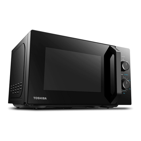
Toshiba ML-EM34P User manual

Toshiba

Toshiba ML-EM34P User manual

Toshiba MM-EM25PF User manual

Toshiba

Toshiba MM-EM25PF User manual

Popular Microwave Oven manuals by other brands

CDA MC50 Manual for installation, use and maintenance

CDA

CDA MC50 Manual for installation, use and maintenance

Tower Hobbies T24021WMRG instruction manual

Tower Hobbies

Tower Hobbies T24021WMRG instruction manual

DAEWOO ELECTRONICS KOR-4125 Service manual

DAEWOO ELECTRONICS

DAEWOO ELECTRONICS KOR-4125 Service manual

Commercial CHEF CHM9MB user manual

Commercial CHEF

Commercial CHEF CHM9MB user manual

Bravetti CONVECTION MICROWAVE OVEN K5345H owner's manual

Bravetti

Bravetti CONVECTION MICROWAVE OVEN K5345H owner's manual

Amana Radarange RSL459P Use & care manual

Amana

Amana Radarange RSL459P Use & care manual

Kenmore 721.63263 Use and care guide

Kenmore

Kenmore 721.63263 Use and care guide

LG MS568 Series owner's manual

LG

LG MS568 Series owner's manual

Zest ZE07120S instruction manual

Zest

Zest ZE07120S instruction manual

Goldstar MV1604ST installation instructions

Goldstar

Goldstar MV1604ST installation instructions

Whirlpool RM288PXV5 Use & care guide

Whirlpool

Whirlpool RM288PXV5 Use & care guide

LG MG6389B owner's manual

LG

LG MG6389B owner's manual

Sharp R-260L Operation manual and cooking guide

Sharp

Sharp R-260L Operation manual and cooking guide

Russell Hobbs RHM2023 instruction manual

Russell Hobbs

Russell Hobbs RHM2023 instruction manual

Malloca MW-944R instruction manual

Malloca

Malloca MW-944R instruction manual

Heinner HMW-20MB user manual

Heinner

Heinner HMW-20MB user manual

san ignacio 52819 instruction manual

san ignacio

san ignacio 52819 instruction manual

Viking RDMOR200SS use and care manual

Viking

Viking RDMOR200SS use and care manual

manuals.online logo
manuals.online logoBrands
  • About & Mission
  • Contact us
  • Privacy Policy
  • Terms and Conditions

Copyright 2025 Manuals.Online. All Rights Reserved.