MBS (Wallmount) Installation - 64523-009 3
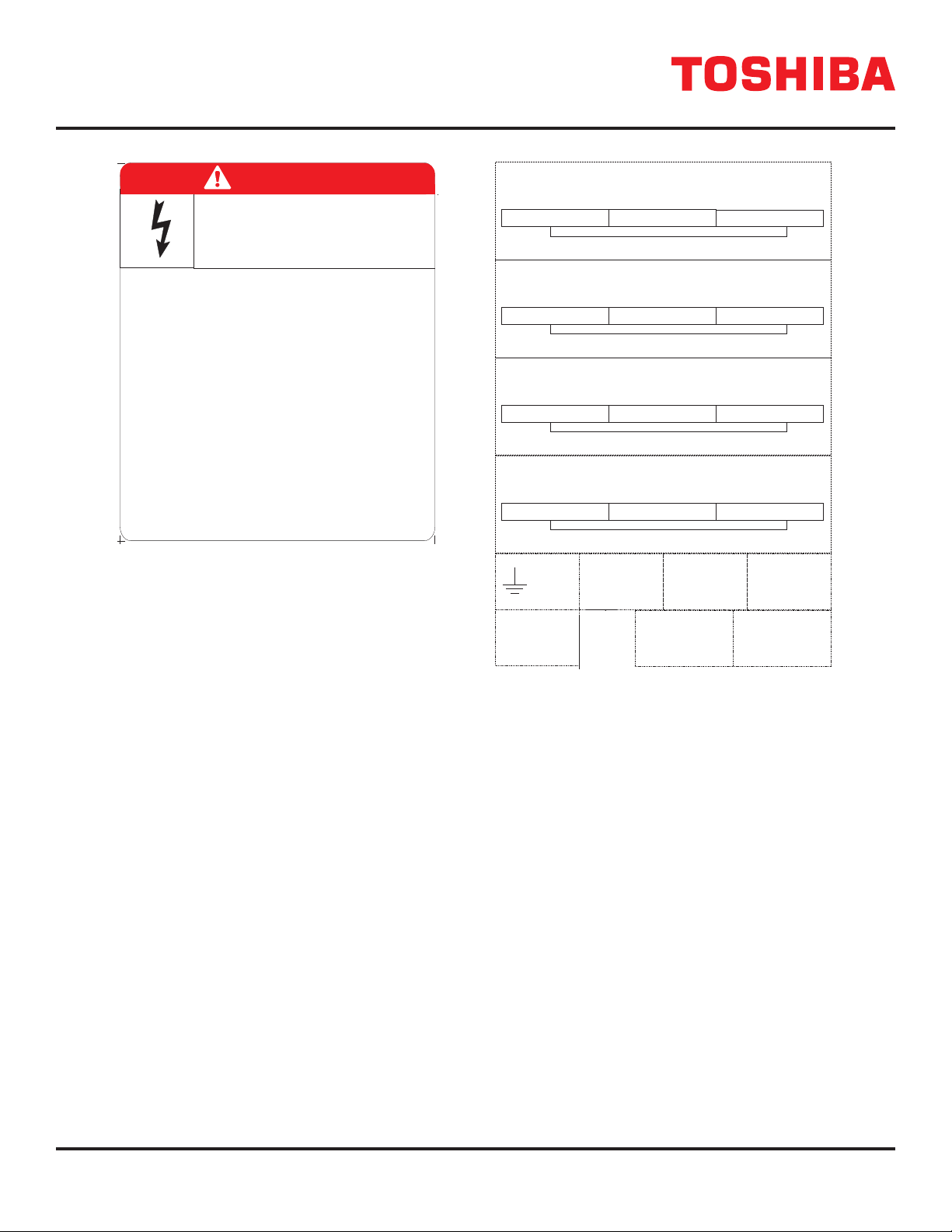
DANGER
Hazardous voltages are used in the operation
of this equipment and could cause severe personal
injury or loss of life.
The following precautions should be observed to
reduce the risk of injury or death.
HAZARDOUS VOLTAGES
Only qualified technicians familiar with this equipment and the
information supplied with it should be permitted to install and
operate this equipment.
Installation of electrical equipment must be done in
accordance with National Electrical Code and any other state
or local codes. Proper grounding and conductor sizing must
be installed for safe operation.
During operation, keep all covers in place and cabinet
doors shut.
When performing visual inspections and maintenance, if
possible, be sure the MBS is turned off and the incoming
AC feed is turned off and locked out.
If it is necessary to make measurements with the power
on, do not touch any electrical connection points. Remove
all jewelry from wrists and fingers. Make sure test equipment
is in good, safe operating condition.
While servicing, stand on some type of insulation, and be
sure not to be grounded.
Follow the safety instructions given in the equipment manual
carefully and observe all danger, warning and caution notices.
64818
MATERIAL - VINYL OR POLYESTER
TEMPERATURE - MINUS 20 TO 100 deg. C
ADHESIVE - V23 OR EQUIV.
MUST RESIST OIL SOLVENTS
ALL MATERIALS USED MUST
BE UL RECOGNIZED
WARNING AREA BACKGROUND COLOR: ANSI DANGER RED
WARNING AREA TEXT COLOR: ANSI WHITE
TEXT AREA BACKGROUND COLOR: ANSI WHITE
TEXT AREA TEXT COLOR: ANSI BLACK
CORNER RADIUS: VENDOR STANDARD
0.00
0.00
3.75
4.50
The UPS and Battery Cabinet will have hazardous
voltages present even after the AC feed is turned off.
THIS MATERIAL IS THE EXCLUSIVE PROPERTY OF TOSHIBA INTERNATIONAL
CORPORATION AND SHALL NOT BE REPRODUCED, USED, OR DISCLOSED
TO OTHERS UNLESS PRIOR WRITTEN AUTHORIZATION IS OBTAINED.
TITLE: SCALE:
DRAWING NO.:
ECN DATE BY
DRAWN: CHECKED: APPROVED:
DANGER LABEL
GENERAL - MBS
64818
FULL
WLM 3-9-11
REV:
0
13131 WEST LITTLE YORK ROAD, HOUSTON, TX 77041 U.S.A.
WLM 3-10-11
ZIR 3-10-11
UNLESS PRIOR WRITTEN AUTHORIZATION IS OBTAINED.
THIS MATERIAL IS THE EXCLUSIVE PROPERTY OF
BE REPRODUCED, USED OR DISCLOSED TO OTHERS
TOSHIBA INTERNATIONAL CORPORATION AND SHALL NOT
APPROVED BY DATE
CHECKED BY
DRAWN BY DATE
DATE
DRAWING NO.
13131 WEST LITTLE YORK ROAD, HOUSTON, TX, 77041 U.S.A.
TITLE SCALE
OFSH.
ORDER NO.
64820
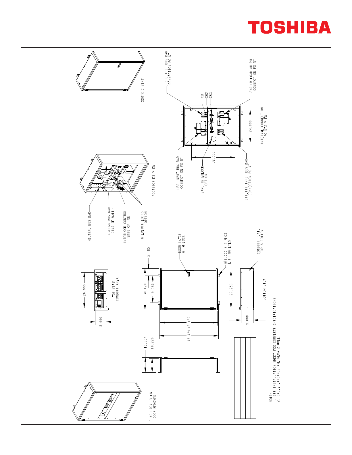
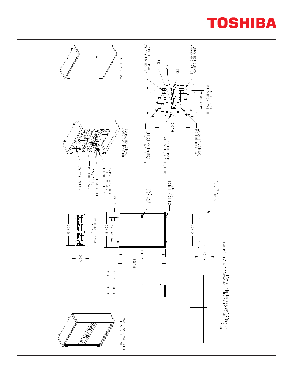
WALL MOUNT MBS CONNECTION
LABEL SHEET
1=1
11
DISK: PRT
REV: 1
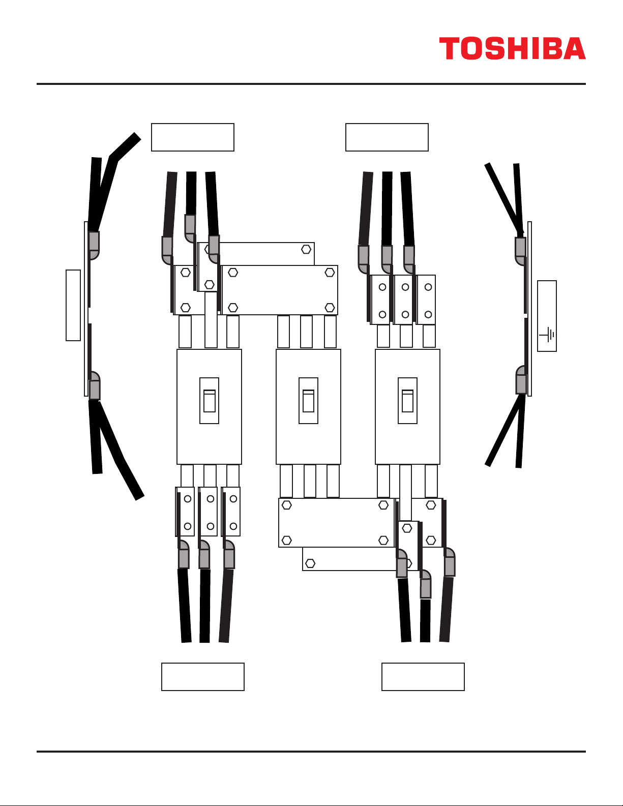
AB C
1/2” BOLT-SAE GRADE 8
TORQUE SPEC: 119 FT LB
ENSURE PROPER PHASING
LINE IN
USE COPPER CONDUCTORS ONLY!
REFER TO INSTRUCTION MANUAL FOR WIRE SIZE
AB C
1/2” BOLT-SAE GRADE 8
TORQUE SPEC: 119 FT LB
ENSURE PROPER PHASING
LOAD IN
USE COPPER CONDUCTORS ONLY!
REFER TO INSTRUCTION MANUAL FOR WIRE SIZE
AB C
1/2” BOLT-SAE GRADE 8
TORQUE SPEC: 119 FT LB
ENSURE PROPER PHASING
UPS IN
USE COPPER CONDUCTORS ONLY!
REFER TO INSTRUCTION MANUAL FOR WIRE SIZE
AB C
1/2” BOLT-SAE GRADE 8
TORQUE SPEC: 119 FT LB
ENSURE PROPER PHASING
UPS OUT
USE COPPER CONDUCTORS ONLY!
REFER TO INSTRUCTION MANUAL FOR WIRE SIZE
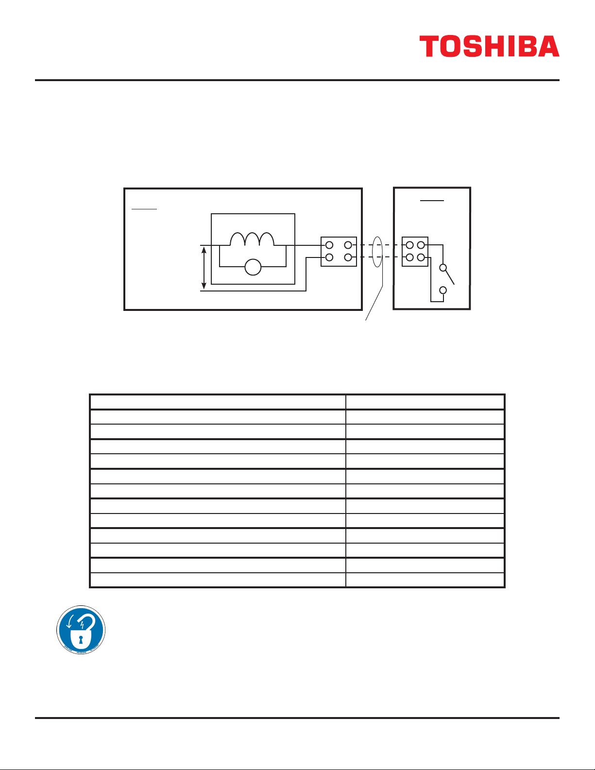
B1 CB2
NEUTRAL
SKRU
B1
1
2
T
C
4.50"
3.50"
1.75"
MATERIAL - POLYESTER
TEMPERATURE - MINUS 20 TO 100 deg. C
ADHESIVE - V23 OR EQUIV.
MUST RESIST OIL SOLVENTS
ALL MATERIALS USED MUST BE UL & RoHS RECOGNIZED
TEXT BACKGROUND: ANSI WHITE OR SILVER
TEXT COLOR: ANSI BLACK
KISS CUT TO BORDER LINES
6.00"
9.00"
1.75"
CB3
GND
INITIAL RELEASE 04-11
ZIR
1.00"
1.50"
1.00"
WLM 4-24-13
3/8” BOLT-SAE GRADE 8
TORQUE SPEC: 47 FT LB
3/8” BOLT-SAE GRADE 8
TORQUE SPEC: 47 FT LB
3/8” BOLT-SAE GRADE 8
TORQUE SPEC: 47 FT LB
3/8” BOLT-SAE GRADE 8
TORQUE SPEC: 47 FT LB
ECO 86630 04-13
WLM
WLM 3-9-11
ZIR 4-24-13
IMPORTANT SAFETY INSTRUCTIONS
SAVE THESE INSTRUCTIONS
This manual contains important instructions that should be followed during the installation, maintenance, and operation of
the MBS to assure safe and proper operation.
1. Turn o, lockout, and tagout all power sources before connecting the power and SKRU wiring to the equipment or
when performing maintenance.
2. Verify the MBS is de-energized before removing the cabinet dead fronts.
3. Verify cables and terminals are de-energized before installing cable in terminals.
Qualied Personnel ONLY!
Qualied Personnel is one that has the skills and knowledge relating to the construction, installation, operation, and main-
tenance of the electrical equipment and has received safety training on the hazards involved (Refer to the latest edition of
NFPA 70E for additional safety requirements).
Qualied Personnel shall:
1. Have read the entire operation manual.
2. Be trained and authorized to safely energize, de-energize, ground, lockout and tag circuits and equipment, and
clear faults in accordance with established safety practices.
3. Be trained in the proper care and use of protective equipment such as safety shoes, rubber gloves, hard hats,
safety glasses, face shields, ash clothing, etc., in accordance with established safety practices.
4. Be trained in rendering rst aid.
5. Be knowledgeable of batteries and the required handling and maintenance precautions.
For further information on workplace safety visit www.osha.gov.