NOTE:
This
Video
Cassette
Recorder
iscompatible
with
any
Video
Cam
Rrrcorder
bearing
the
mark.
The
VCR
is
designed
to
expand
your
opportunities
for
home
viewing
and
not
for
any
usage
which
mightviolate
the
copyright
laws
.
Swre
the original
shipping
carton
and
paeking
rnaterlals;
they
will
came
in
handy
if
you
ever
have
to
ship
your
VCR
.
For
maximum
protection.
repack
the
set
B
it
wss
originally
packed
at
the
factory
.
TABLE
OF
CONTENTS
.................................................
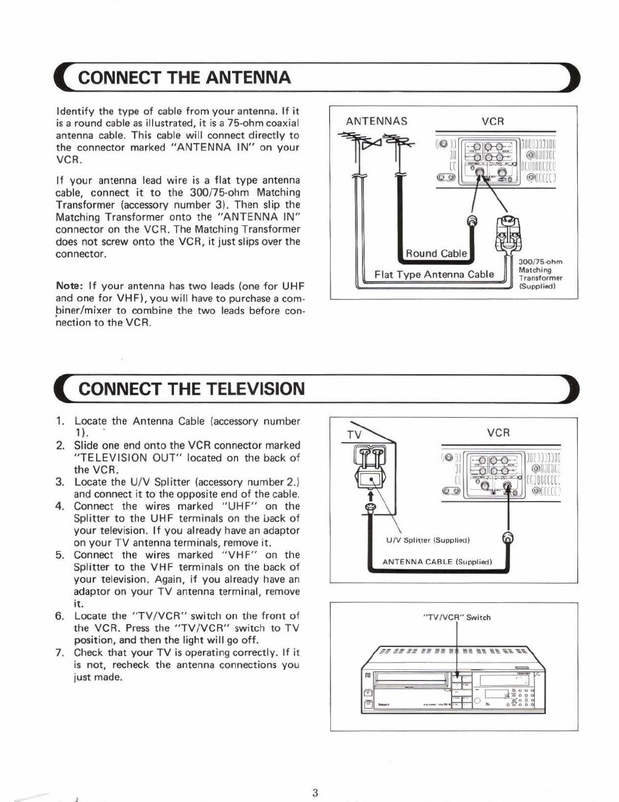
CONNECT
THE
ANTENNA
3
...............................................
CONNECT
THE
TELEVISION
3
CABLE
ANTENNA
CONNECTION
............................................
4
TELECAPTION
ADAPTOR
CONNECTION
.....................................
4
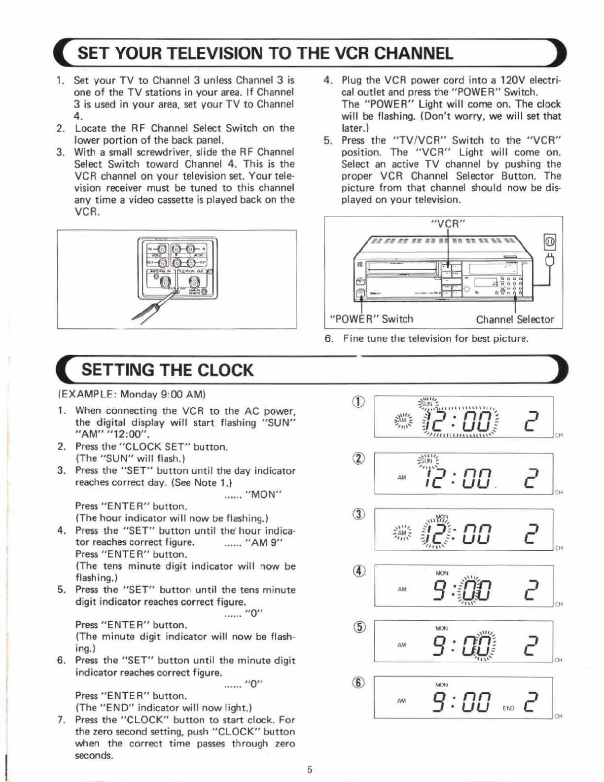
SET
YOUR
TELEVISION
TO
THE
VCR CHANNEL
..............................
5
SET
TI
NG
THE
CLOCK
...................................................
5-6
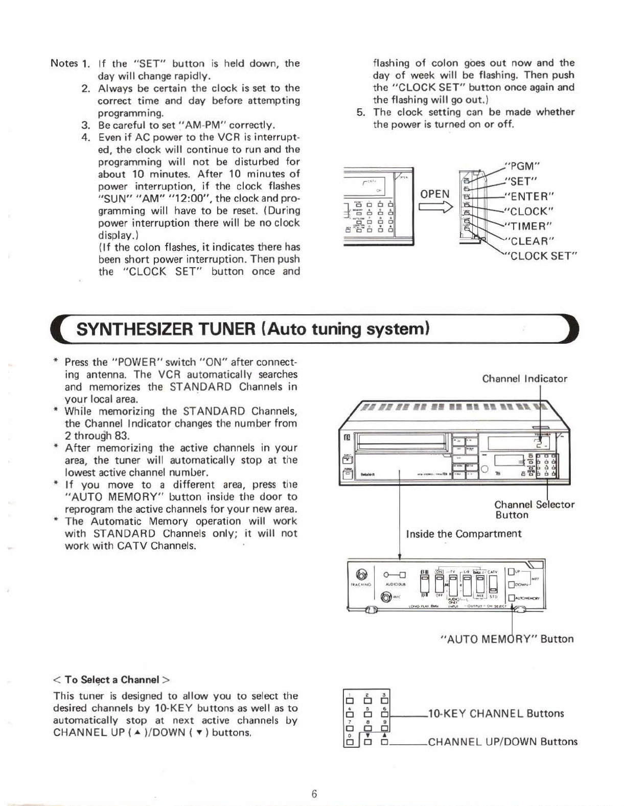
SYNTHESIZER TUNER
(Auto
tuning
system)
.................................
6-8
MAKING
A
SAMPLE
RECORDING
AND
PLAYBACK
............................
8
PLAYBACK
WITH
N
EQUIPPEDWITH
VlR
...................................
8
GET
FAMILIAR WITH
YOUR
VCR
...........................................
8
IDENTIFICATIONAND OPERATION
OF
CONTROLS
........................
9-20
AUDIODUBBING
........................................................
21
EDITING RECORDING
...................................................
21
RECORDING
ONE
PROGRAM
WHILE
VIEWING
ANOTHER
.....................
n
VCR
TO
VCR DUBBING
...................................................
22
USING
A
CAMERA
WITH THE
VCR
.........................................
23
PROGRAMMABLE
TIMER
.............................................
.2
4-27
CONFIRMINGTHAT
PROGRAM(S1
ARE
PRESET
..............................
27
TO
CANCELPREVIOUSLY TIMED PROGRAM(S1
..............................
27
US1
NG
THE
"PICTURE
SEARCH"
(CUE
AND
REV1
EW)
FEATURES
...............
28
USING
THE
"AUTO
FIND" FEATURE
.......................................
20
USING
THE
"MEMORY"
FEATURE
.........................................
29
USING
THE
TAPE
"COUNTERIPLAY
TIME"
FEATURE
.........................
30
TIMEITAPE
COUNTER
CHART
.............................................
30
HOW
TO
INSTALL BATTERIES
IN
THE
REMOTE
CONTROL
UNIT
...............
31
REMOTE
CONTROL
OPERATION
RANGE
...................................
31
USING
THE REMOTE
CONTROL
SPECIAL
FEATURES
.........................
32
FORWARDSLOW
........................................................
32
OOUB
tE
SPEED
PLAYBACK
...............................................
32
VARIABLE
"SEARCH"
(5-20
times normal
playbck)
...........................
32
............................
I
SPECIAL
FEATURE:
"BETA
hi-fi"
SOUND
SYSTEM
331
WHAT
IS
"BETA
hi-fi"?
...................................................
33
.........................
"BETA
hi-fi"
RECORDINGPLAYBACK CONNECTIONS
34
HOW
TO
OPERATE
SWITCHES
TO
RECORD
A
TAPE
WlTH
"BETA
hi-fi8'SOUND
.....................................................
35
HOW
TO
OPERATE SWITCHES
TO
PLAYBACK
A
TAPE
PRE-RECORDED
WlTH
]
"BETA
hi-fi"
SOUND
.....................................................
361
.........................................................
DEWWARNING
37
......................................................
OPERATINGHINTS
37
TROUBLESHOOTING
................................................
-38-39
SPECIFICATIONS
........................................................
40