Toshiba RDXV49DTKF User manual

SERVICE MANUAL
TOSHIBA CORPORATION 2009
The above model is classified as a green product (*1), as indicated by the underlined serial
number. This Service Manual describes replacement parts for the green product. When
repairing this green product, use the part(s) described in this manual and lead-free solder (*2).
For (*1) and (*2), see the next page.
FILE NO. 810-200923GR
HDD &DVD
/Video Cassette Recorder
RDXV49DTKF
Published in Japan, May 2009 GREEN
SECAMPAL
REVISED: 01

(*1) GREEN PRODUCT PROCUREMENT
The EC is actively promoting the WEEE & RoHS Directives that define standards for recycling
and reuse of Waste Electrical and Electronic Equipment and for the Restriction of the use of
certain Hazardous Substances. From July 1, 2006, the RoHS Directive will prohibit any
marketing of new products containing the restricted substances.
Increasing attention is given to issues related to the global environmental. Toshiba Corporation
recognizes environmental protection as a key management tasks, and is doing its utmost to
enhance and improve the quality and scope of its environmental activities. In line with this,
Toshiba proactively promotes Green Procurement, and seeks to purchase and use products,
parts and materials that have low environmental impacts.
Green procurement of parts is not only confined to manufacture. The same green parts used in
manufacture must also be used as replacement parts.
(*2) LEAD-FREE SOLDER
This product is manufactured using lead-free solder as a part of a movement within the consumer
products industry at large to be environmentally responsible. Lead-free solder must be used in the
servicing and repair of this product.
WARNING
This product is manufactured using lead free solder.
DO NOT USE LEAD BASED SOLDER TO REPAIR THIS PRODUCT !
The melting temperature of lead-free solder is higher than that of leaded solder by 86°F to 104°F
(30°C to 40°C). Use of a soldering iron designed for lead-based solders to repair product made
with lead-free solder may result in damage to the component and or BOARD being soldered.
Great care should be made to ensure high-quality soldering when servicing this product —
especially when soldering large components, through-hole pins, and on BOARDs — as the level
of heat required to melt lead-free solder is high.

MAIN SECTION
HDD & DVD
/ Video Cassette Recorder
RDXV49DTKF
TABLE OF CONTENTS
Specifications. . . . . . . . . . . . . . . . . . . . . . . . . . . . . . . . . . . . . . . . . . . . . . . . . . . . . . . . . . . . . . . . . . . . . . . . . . 1-1-1
Laser Beam Safety Precautions. . . . . . . . . . . . . . . . . . . . . . . . . . . . . . . . . . . . . . . . . . . . . . . . . . . . . . . . . . . . 1-2-1
Important Safety Precautions. . . . . . . . . . . . . . . . . . . . . . . . . . . . . . . . . . . . . . . . . . . . . . . . . . . . . . . . . . . . . . 1-3-1
Standard Notes for Servicing . . . . . . . . . . . . . . . . . . . . . . . . . . . . . . . . . . . . . . . . . . . . . . . . . . . . . . . . . . . . . . 1-4-1
Handling Precautions for HDD . . . . . . . . . . . . . . . . . . . . . . . . . . . . . . . . . . . . . . . . . . . . . . . . . . . . . . . . . . . . . 1-5-1
Preparation for Servicing . . . . . . . . . . . . . . . . . . . . . . . . . . . . . . . . . . . . . . . . . . . . . . . . . . . . . . . . . . . . . . . . . 1-6-1
Cabinet Disassembly Instructions . . . . . . . . . . . . . . . . . . . . . . . . . . . . . . . . . . . . . . . . . . . . . . . . . . . . . . . . . . 1-7-1
Electrical Adjustment Instructions . . . . . . . . . . . . . . . . . . . . . . . . . . . . . . . . . . . . . . . . . . . . . . . . . . . . . . . . . . 1-8-1
How to Self-Check and HDD Format . . . . . . . . . . . . . . . . . . . . . . . . . . . . . . . . . . . . . . . . . . . . . . . . . . . . . . . . 1-9-1
How to Initialize the HDD & DVD/VCR . . . . . . . . . . . . . . . . . . . . . . . . . . . . . . . . . . . . . . . . . . . . . . . . . . . . . . 1-10-1
Firmware Renewal Mode . . . . . . . . . . . . . . . . . . . . . . . . . . . . . . . . . . . . . . . . . . . . . . . . . . . . . . . . . . . . . . . . 1-11-1
Remote Control Key Code . . . . . . . . . . . . . . . . . . . . . . . . . . . . . . . . . . . . . . . . . . . . . . . . . . . . . . . . . . . . . . . 1-12-1
Troubleshooting . . . . . . . . . . . . . . . . . . . . . . . . . . . . . . . . . . . . . . . . . . . . . . . . . . . . . . . . . . . . . . . . . . . . . . . 1-13-1
Function Indicator Symbols . . . . . . . . . . . . . . . . . . . . . . . . . . . . . . . . . . . . . . . . . . . . . . . . . . . . . . . . . . . . . . 1-14-1
Block Diagrams . . . . . . . . . . . . . . . . . . . . . . . . . . . . . . . . . . . . . . . . . . . . . . . . . . . . . . . . . . . . . . . . . . . . . . . 1-15-1
Schematic Diagrams / BOARD and Test Points . . . . . . . . . . . . . . . . . . . . . . . . . . . . . . . . . . . . . . . . . . . . . . . 1-16-1
Waveforms . . . . . . . . . . . . . . . . . . . . . . . . . . . . . . . . . . . . . . . . . . . . . . . . . . . . . . . . . . . . . . . . . . . . . . . . . . . 1-17-1
Wiring Diagram . . . . . . . . . . . . . . . . . . . . . . . . . . . . . . . . . . . . . . . . . . . . . . . . . . . . . . . . . . . . . . . . . . . . . . . 1-18-1
System Control Timing Chart. . . . . . . . . . . . . . . . . . . . . . . . . . . . . . . . . . . . . . . . . . . . . . . . . . . . . . . . . . . . . 1-19-1
IC Pin Function Descriptions . . . . . . . . . . . . . . . . . . . . . . . . . . . . . . . . . . . . . . . . . . . . . . . . . . . . . . . . . . . . . 1-20-1
Lead Identifications . . . . . . . . . . . . . . . . . . . . . . . . . . . . . . . . . . . . . . . . . . . . . . . . . . . . . . . . . . . . . . . . . . . . 1-21-1
Exploded Views . . . . . . . . . . . . . . . . . . . . . . . . . . . . . . . . . . . . . . . . . . . . . . . . . . . . . . . . . . . . . . . . . . . . . . . 1-22-1
Mechanical Parts List . . . . . . . . . . . . . . . . . . . . . . . . . . . . . . . . . . . . . . . . . . . . . . . . . . . . . . . . . . . . . . . . . . . 1-23-1
Electrical Parts List . . . . . . . . . . . . . . . . . . . . . . . . . . . . . . . . . . . . . . . . . . . . . . . . . . . . . . . . . . . . . . . . . . . . 1-24-1
Main Section
ISpecifications
IPreparation for Servicing
IAdjustment Procedures
ISchematic Diagrams
IBOARD
IExploded Views
IParts List
Manufactured under license from Dolby Laboratories.
Dolby and the double-D symbol are trademarks of Dolby Laboratories.

1-1-1 E3TK0SP
SPECIFICATIONS

1-2-1 DRVHDP_LBSP
LASER BEAM SAFETY PRECAUTIONS
This DVD player uses a pickup that emits a laser beam.
The laser beam is emitted from the location shown in the figure. When checking the laser diode, be sure to keep
your eyes at least 30 cm away from the pickup lens when the diode is turned on. Do not look directly at the laser
beam.
CAUTION: Use of controls and adjustments, or doing procedures other than those specified herein, may result in
hazardous radiation exposure.
Location: Inside Top of DVD mechanism.
Do not look directly at the laser beam coming
from the pickup or allow it to strike against your
skin.
Drive Mechanism Assembly
Laser Beam Radiation
Laser Pickup
Turntable

1-3-1 DVDP_ISP
IMPORTANT SAFETY PRECAUTIONS
Product Safety Notice
Some electrical and mechanical parts have special
safety-related characteristics which are often not
evident from visual inspection, nor can the protection
they give necessarily be obtained by replacing them
with components rated for higher voltage, wattage,
etc. Parts that have special safety characteristics are
identified by a !on schematics and in parts lists. Use
of a substitute replacement that does not have the
same safety characteristics as the recommended
replacement part might create shock, fire, and/or other
hazards. The Product’s Safety is under review
continuously and new instructions are issued
whenever appropriate. Prior to shipment from the
factory, our products are carefully inspected to confirm
with the recognized product safety and electrical
codes of the countries in which they are to be sold.
However, in order to maintain such compliance, it is
equally important to implement the following
precautions when a set is being serviced.
Precautions during Servicing
A. Parts identified by the !symbol are critical for
safety. Replace only with part number specified.
B. In addition to safety, other parts and assemblies
are specified for conformance with regulations
applying to spurious radiation. These must also be
replaced only with specified replacements.
Examples: RF converters, RF cables, noise
blocking capacitors, and noise blocking filters, etc.
C. Use specified internal wiring. Note especially:
1) Wires covered with PVC tubing
2) Double insulated wires
3) High voltage leads
D. Use specified insulating materials for hazardous
live parts. Note especially:
1) Insulation tape
2) PVC tubing
3) Spacers
4) Insulators for transistors
E. When replacing AC primary side components
(transformers, power cord, etc.), wrap ends of
wires securely about the terminals before
soldering.
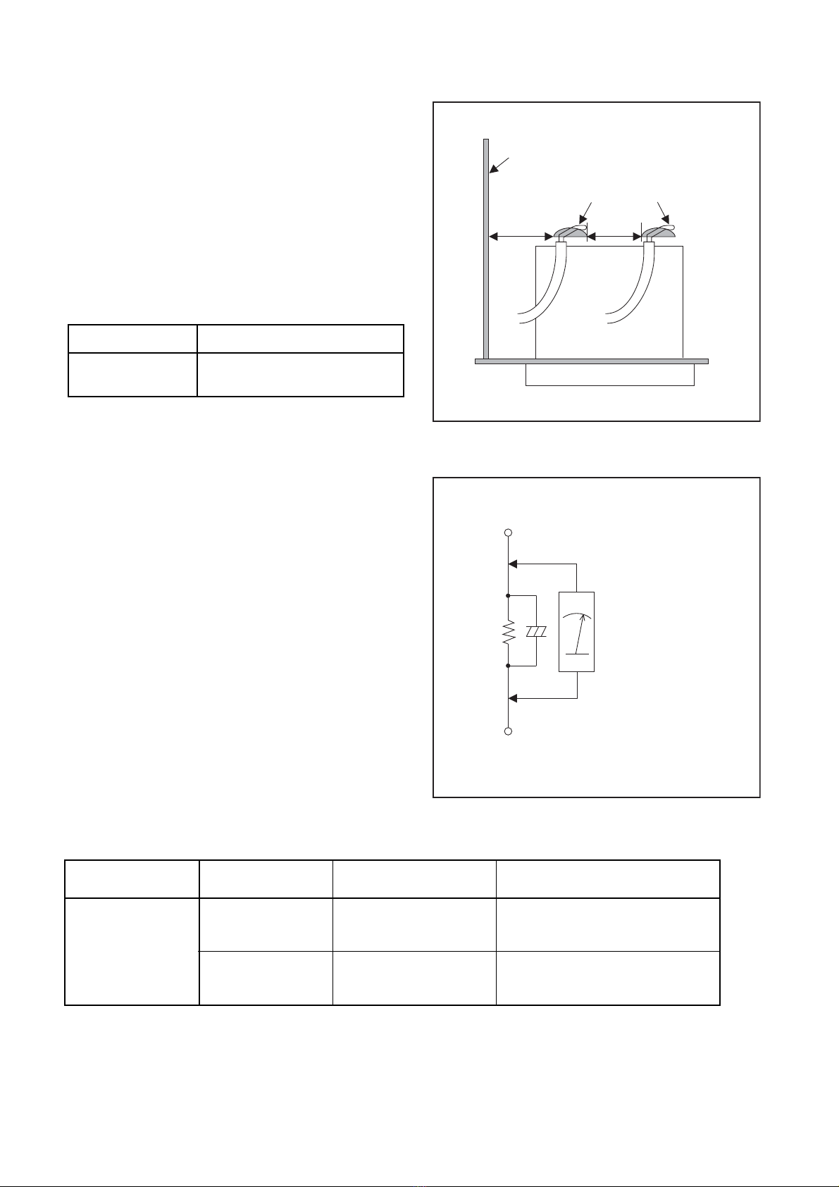
F. Observe that the wires do not contact heat
producing parts (heatsinks, oxide metal film
resistors, fusible resistors, etc.).
G. Check that replaced wires do not contact sharp
edges or pointed parts.
H. When a power cord has been replaced, check that
5 - 6 kg of force in any direction will not loosen it.
I. Also check areas surrounding repaired locations.
J. Be careful that foreign objects (screws, solder
droplets, etc.) do not remain inside the set.
K. When connecting or disconnecting the internal
connectors, first, disconnect the AC plug from the
AC outlet.
L. Be sure to confirm the FAN motor has completely
stopped when disconnecting the AC cord for
termination processing is activated during inner P-
on immediately after turning Power off.

1-3-2 DVDP_ISP
Safety Check after Servicing
Examine the area surrounding the repaired location for
damage or deterioration. Observe that screws, parts,
and wires have been returned to their original positions.
Afterwards, do the following tests and confirm the
specified values to verify compliance with safety
standards.
1. Clearance DistanceDistance
When replacing primary circuit components, confirm
specified clearance distance (d) and (d’) between
soldered terminals, and between terminals and
surrounding metallic parts. (See Fig. 1)
Table 1 : Ratings for selected area
Note: This table is unofficial and for reference only.
Be sure to confirm the precise values.
2. Leakage Current Test
Confirm the specified (or lower) leakage current
between B (earth ground, power cord plug prongs) and
externally exposed accessible parts (RF terminals,
antenna terminals, video and audio input and output
terminals, microphone jacks, earphone jacks, etc.) is
lower than or equal to the specified value in the table
below.
Measuring Method (Power ON) :
Insert load Z between B (earth ground, power cord plug
prongs) and exposed accessible parts. Use an AC
voltmeter to measure across the terminals of load Z.
See Fig. 2 and the following table.
AC Line Voltage Clearance Distance (d), (d’)
230 V t3.2 mm(d)
t6.0 mm(d’)
Chassis or Secondary Conductor
Primary Circuit
Fig. 1
d' d
AC Voltmeter
(High Impedance)
Exposed Accessible Part
BOne side of
Power Cord Plug Prongs
Z
Fig. 2
Table 2: Leakage current ratings for selected areas
Note: This table is unofficial and for reference only. Be sure to confirm the precise values.
AC Line Voltage Load Z Leakage Current (i) One side of power cord plug
prongs (B) to:
230 V
2k:RES.
Connected in
parallel
id0.7mA AC Peak
id2mA DC
RF or
Antenna terminals
50k:RES.
Connected in
parallel
id0.7mA AC Peak
id2mA DC A/V Input, Output

1-4-1 DVDP_SN
STANDARD NOTES FOR SERVICING
Circuit Board Indications
1. The output pin of the 3 pin Regulator ICs is
indicated as shown.
2. For other ICs, pin 1 and every fifth pin are
indicated as shown.
3. The 1st pin of every male connector is indicated as
shown.
Instructions for Connectors
1. When you connect or disconnect the FFC (Flexible
Foil Connector) cable, be sure to first disconnect
the AC cord.
2. FFC (Flexible Foil Connector) cable should be
inserted parallel into the connector, not at an
angle.
Pb (Lead) Free Solder
When soldering, be sure to use the Pb free solder.
How to Remove / Install Flat Pack-IC
1. Removal
With Hot-Air Flat Pack-IC Desoldering Machine:
1. Prepare the hot-air flat pack-IC desoldering
machine, then apply hot air to the Flat Pack-IC
(about 5 to 6 seconds). (Fig. S-1-1)
2. Remove the flat pack-IC with tweezers while
applying the hot air.
3. Bottom of the flat pack-IC is fixed with glue to the
BOARD; when removing entire flat pack-IC, first
apply soldering iron to center of the flat pack-IC
and heat up. Then remove (glue will be melted).
(Fig. S-1-6)
4. Release the flat pack-IC from the BOARD using
tweezers. (Fig. S-1-6)
CAUTION:
1. The Flat Pack-IC shape may differ by models. Use
an appropriate hot-air flat pack-IC desoldering
machine, whose shape matches that of the Flat
Pack-IC.
2. Do not supply hot air to the chip parts around the
flat pack-IC for over 6 seconds because damage
to the chip parts may occur. Put masking tape
around the flat pack-IC to protect other parts from
damage. (Fig. S-1-2)
NOTE: BOARD MEANS PRINTED CIRCUIT BOARD.
Top View
Out In
Bottom View
Input
5
10
Pin 1
Pin 1
FFC Cable
Connector
BOARD
* Be careful to avoid a short circuit.
Fig. S-1-1

1-4-2 DVDP_SN
3. The flat pack-IC on the BOARD is affixed with
glue, so be careful not to break or damage the foil
of each pin or the solder lands under the IC when
removing it.
With Soldering Iron:
1. Using desoldering braid, remove the solder from
all pins of the flat pack-IC. When you use solder
flux which is applied to all pins of the flat pack-IC,
you can remove it easily. (Fig. S-1-3)
2. Lift each lead of the flat pack-IC upward one by
one, using a sharp pin or wire to which solder will
not adhere (iron wire). When heating the pins, use
a fine tip soldering iron or a hot air desoldering
machine. (Fig. S-1-4)
3. Bottom of the flat pack-IC is fixed with glue to the
BOARD; when removing entire flat pack-IC, first
apply soldering iron to center of the flat pack-IC
and heat up. Then remove (glue will be melted).
(Fig. S-1-6)
4. Release the flat pack-IC from the BOARD using
tweezers. (Fig. S-1-6)
Hot-air
Flat Pack-IC
Desoldering
Machine
BOARD
Flat Pack-IC
Tweezers
Masking
Tape
Fig. S-1-2
Flat Pack-IC Desoldering Braid
Soldering Iron
Fig. S-1-3
Fine Tip
Soldering Iron
Sharp
Pin
Fig. S-1-4

1-4-3 DVDP_SN
With Iron Wire:
1. Using desoldering braid, remove the solder from
all pins of the flat pack-IC. When you use solder
flux which is applied to all pins of the flat pack-IC,
you can remove it easily. (Fig. S-1-3)
2. Affix the wire to a workbench or solid mounting
point, as shown in Fig. S-1-5.
3. While heating the pins using a fine tip soldering
iron or hot air blower, pull up the wire as the solder
melts so as to lift the IC leads from the BOARD
contact pads as shown in Fig. S-1-5.
4. Bottom of the flat pack-IC is fixed with glue to the
BOARD; when removing entire flat pack-IC, first
apply soldering iron to center of the flat pack-IC
and heat up. Then remove (glue will be melted).
(Fig. S-1-6)
5. Release the flat pack-IC from the BOARD using
tweezers. (Fig. S-1-6)
Note: When using a soldering iron, care must be
taken to ensure that the flat pack-IC is not
being held by glue. When the flat pack-IC is
removed from the BOARD, handle it gently
because it may be damaged if force is applied.
2. Installation
1. Using desoldering braid, remove the solder from
the foil of each pin of the flat pack-IC on the
BOARD so you can install a replacement flat pack-
IC more easily.
2. The “●” mark on the flat pack-IC indicates pin 1.
(See Fig. S-1-7.) Be sure this mark matches the 1
on the BOARD when positioning for installation.
Then presolder the four corners of the flat pack-IC.
(See Fig. S-1-8.)
3. Solder all pins of the flat pack-IC. Be sure that
none of the pins have solder bridges.
To Solid
Mounting Point
Soldering Iron
Iron Wire
or
Hot Air Blower
Fig. S-1-5
Fine Tip
Soldering Iron
BOARD
Flat Pack-IC
Tweezers
Fig. S-1-6
Example :
Pin 1 of the Flat Pack-IC
is indicated by a " " mark. Fig. S-1-7
Presolder
BOARD
Flat Pack-IC
Fig. S-1-8

1-4-4 DVDP_SN
Instructions for Handling Semi-
conductors
Electrostatic breakdown of the semi-conductors may
occur due to a potential difference caused by
electrostatic charge during unpacking or repair work.
1. Ground for Human Body
Be sure to wear a grounding band (1 M:) that is
properly grounded to remove any static electricity that
may be charged on the body.
2. Ground for Workbench
Be sure to place a conductive sheet or copper plate
with proper grounding (1 M:) on the workbench or
other surface, where the semi-conductors are to be
placed. Because the static electricity charge on
clothing will not escape through the body grounding
band, be careful to avoid contacting semi-conductors
with your clothing.
<Incorrect>
BOARD
Grounding Band
Conductive Sheet or
Copper Plate
1MΩ
1MΩ
<Correct>
BOARD

1-5-1 DHDP_SN
HANDLING PRECAUTIONS FOR HDD
CAUTION:
1. SHOCK
a. Exposing HDD to shock may be the biggest
damaging factor. Please note that HDD is easily
damaged even if dropped from any height. Be sure
to place HDD on a shock-absorbent mat. Also, be
careful when transporting HDD.
b. Be careful not to subject HDD to any shock when
tightening screws for HDD replacement.
(Tighten screws manually, not with an electric
driver.)
2. MOISTURE
a. Moisture may also be a damaging factor. HDD is
semiclosed style. Sudden changes in ambient
temperature may cause moisture to form. Monitor
temperature and do not allow moisture to form on
the media surface. Also, when opening HDD
package, do so only after package is at ambient
temperature.
b. After replacing HDD, leave it to reach room
temperature (about 2 hours) for preventing dew
internal condensation, and then work necessary
task such as operation check.
3. STATIC ELECTRICITY
a. After removing HDD or taking replacement HDD
out of the protective bag (the replacement HDD is
packed in a protective bag), place HDD on a
conductive surface. A grounding band should be
worn when handling.
Both the conductive surface and grounding band
should be grounded.
b. Make sure that HDD is placed on main unit
completely and then let go of it, when assembling.
c. Do not put HDD on a packing bag. (for preventing
electrostatic damage)
4. OTHERS
a. Be careful so as not to do the followings.
Otherwise, HDD might be damaged.
-DO NOT disassemble HDD.
- When handling HDD, be sure to hold both sides
securely.
b. HDD should be stored, packed in the protective
bag, in suitable surroundings (i.e., no extreme
changes in temperature to avoid condensation).
c. When transporting HDD, be sure to use the
exclusive packing case (the replacement HDD
carton).
d. Do not stack HDDs.
e. Do not place vertically because HDD is unstable
and easy to fall.
Grounding Band

1-6-1 E3TK0PFS
PREPARATION FOR SERVICING
How to Enter the Service Mode
About Optical Sensors
Caution:
An optical sensor system is used for the Tape Start
and End Sensors on this equipment. Carefully read
and follow the instructions below. Otherwise the unit
may operate erratically.
What to do for preparation
Insert a tape into the Deck Mechanism Assembly and
press [ B] (VCR) button. The tape will be loaded into
the Deck Mechanism Assembly. Make sure the power
is on, connect JP278 (S-INH) to GND. This will stop
the function of Tape Start Sensor, Tape End Sensor
and Reel Sensors. (If these TPs are connected before
plugging in the unit, the function of the sensors will
stay valid.) See Fig. 1.
Note: Because the Tape End Sensors are inactive,
do not run a tape all the way to the start or the
end of the tape to avoid tape damage.
Q504
Q503
JP278 (S-INH)
Fig. 1

1-7-1 E3TK0DC
CABINET DISASSEMBLY INSTRUCTIONS
1. Disassembly Flowchart
This flowchart indicates the disassembly steps to gain
access to item(s) to be serviced. When reassembling,
follow the steps in reverse order. Bend, route, and
dress the cables as they were originally.
2. Disassembly Method
NOTE: BOARD MEANS PRINTED CIRCUIT BOARD.
ID/
LOC.
No.
PART
REMOVAL
Fig.
No.
REMOVE/*UNHOOK/
UNLOCK/RELEASE/
UNPLUG/DESOLDER
Note
[1] Cover Top D1 9(S-1) ---
[2] Front
Assembly D2
*4(L-1), *3(L-2), (S-2),
2(S-3), *CN6001,
USB Holder, USB
Plate Earth,
1
[3] BOARD
USB D2 ---------- ---
[4] Front
Bracket D2 3(S-4), (S-5), Front
Support ---
[1] Cover Top
[2] Front
Assembly
[4] Front Bracket
[25] Front
Bracket R [26] Bracket R
[6] HDD Assembly
[8] HDD Unit
[9] HDD Support
[10] HDD Bracket
[22] BOARD
REAR JACK
[5] DVD Mechanism
& DVD/HDD MAIN
BOARD Assembly
[14] BOARD
POWER SUPPLY
[15] Power Holder
[17] BOARD
FUNCTION
[11] Fan Holder
[12] Motor DC Fan
[13] Panel Rear
[20] Deck
Assembly
[24] Deck Pedestal
[19] VCR
Chassis Unit
[16] BOARD
SWITCH
[18] BOARD
POWER SWITCH
[3] BOARD USB
[23] BOARD AV
[21] BOARD DTV
MODULE Unit
[7] BOARD SATA
[5]
DVD
Mechanism
& DVD/
HDD MAIN
BOARD
Assembly
D3
(S-6), 2(S-7), 2(S-8),
2(S-9), *CN101,
*CN502-D, *CN652,
*CN701, *CN901,
*CN981, Connector,
Dust Cover, Hook,
Mecha Plate Earth
2
[6] HDD
Assembly D3 2(S-10), (S-11),
Connector ---
[7] BOARD
SATA D4 *CN5003 ---
[8] HDD Unit D4 4(S-12) 3
[9] HDD
Support D4 4(S-13), HDD Rubber ---
[10] HDD
Bracket D4 ---------- ---
[11] Fan Holder D5 2(S-14), *CN1002-P ---
[12] Motor DC
Fan D5 2(S-15) ---
[13] Panel Rear D5 2(S-16), 5(S-17),
Rear Holder ---
[14]
BOARD
POWER
SUPPLY
D6
(S-18), 3(S-19),
(S-20), *CL1001,
*CN6005, FFC Guide
---
[15] Power
Holder D6 ---------- ---
[16] BOARD
SWITCH D6 (S-21), Desolder ---
[17] BOARD
FUNCTION D6 2(S-22), *CN1504 ---
[18]
BOARD
POWER
SWITCH
D7 (S-23), Desolder ---
[19]
VCR
Chassis
Unit
D7 5(S-24), 4(S-25) ---
[20] Deck
Assembly D8 (S-26), (S-27) 4
5
[21]
BOARD
DTV
MODULE
Unit
D8 Desolder ---
[22]
BOARD
REAR
JACK
D8 Desolder ---
[23] BOARD AV D8 ---------- ---
ID/
LOC.
No.
PART
REMOVAL
Fig.
No.
REMOVE/*UNHOOK/
UNLOCK/RELEASE/
UNPLUG/DESOLDER
Note

1-7-2 E3TK0DC
Note:
(1): Identification (location) No. of parts in the figures
(2): Name of the part
(3): Figure Number for reference
(4): Identification of parts to be removed, unhooked,
unlocked, released, unplugged, unclamped, or
desoldered.
P=Spring, L=Locking Tab, S=Screw,
CN=Connector
*=Unhook, Unlock, Release, Unplug, or Desolder
e.g. 6(S-1) = six Screws (S-1),
5(L-1) = five Locking Tabs (L-1)
(5): Refer to “Reference Notes.”
Reference Notes
1. Locking Tabs (L-1) and (L-2) are fragile. Be careful
not to break them.
1-1. Remove Screw (S-2).
1-2. Release four Locking Tabs (L-1).
1-3. Release three Locking Tabs (L-2).
1-4. Disconnect Connector (CN6001), and
remove the Front Assembly.
2. The DVD Mechanism & DVD/HDD MAIN BOARD
Assembly is adjusted as a unit at factory.
Therefore, do not disassemble it. Replace the
DVD Mechanism & DVD/HDD MAIN BOARD
Assembly as a unit.
3. Whenever you have replaced the HDD unit, format
the HDD unit. To format the HDD unit, perform the
following.
3-1. To put the HDD & DVD/VCR into the HDD
mode, press the [HDD] button on the remote
control unit.
3-2. To put the HDD & DVD/VCR into the self-
check mode, after pressing [VARIABLE
SKIP] button, press the [0], [7], and [9]
buttons on the remote control in that order
within three seconds.
3-3. Press [ENTER/OK] button. The HDD & DVD/
VCR is formatted and the power is turned off
automatically after two seconds.
4. When reassembling, solder wire jumpers as
shown in Fig. D8.
5. Before installing the Deck Assembly, be sure to
place the pin of LD-SW on the BOARD AV as
shown in Fig. D8. Then, install the Deck Assembly
while aligning the hole of Cam Gear with the pin of
LD-SW, the shaft of Cam Gear with the hole of LD-
SW as shown in Fig. D8.
[24] Deck
Pedestal D9 7(S-28) ---
[25] Front
Bracket R D9 (S-29), 2(S-30), DV
Cable, DV Plate Earth ---
[26] Bracket R D9 2(S-31) ---
p
(1)
p
(2)
p
(3)
p
(4)
p
(5)
ID/
LOC.
No.
PART
REMOVAL
Fig.
No.
REMOVE/*UNHOOK/
UNLOCK/RELEASE/
UNPLUG/DESOLDER
Note
(S-1)
(S-1)
(S-1)
(S-1)
[1] Cover Top
Fig. D1

1-7-3 E3TK0DC
(L-1)
(L-2)
(L-1)
(S-5)
(S-4)
(S-2)
Front
Support
USB Holder
CN6001
USB Plate Earth
[2] Front Assembly
[3] BOARD
USB
[4] Front Bracket
(S-4)
(S-4)
(S-3)
Fig. D2
(S-10)
(S-9)
CN101
CN901
CN701
CN981
Mecha Plate
Earth
CN652
CN502-D
(S-11)
(S-7)
(S-6)
Connector
* See Reference Notes 2.
Dust
Cover
Hook
[6] HDD Assembly
[5] *DVD
Mechanism
& DVD/HDD
MAIN BOARD
Assembly
(S-7)
(S-8)
Fig. D3
(S-13) (S-13)
(S-12) (S-12)
CN5003
[10] HDD Bracket
[8] HDD Unit
[9] HDD Support
[7] BOARD
SATA
HDD Rubber
HDD Rubber
Fig. D4
(S-14)
(S-17)
(S-16)
(S-17)
(S-16)
(S-15)
[12] Motor
DC Fan
[11] Fan Holder
[13] Panel Rear
CN1002-P
Rear Holder
Fig. D5

1-7-4 E3TK0DC
FFC Guide
CL1001
CN6005
(S-21)
(S-22)
(S-18)
(S-19)
(S-20)
[14] BOARD
POWER SUPPLY
[15] Power
Holder
[17] BOARD
FUNCTION
[16] BOARD SWITCH
Desolder
CN1504
Fig. D6
(S-24)
(S-23)
(S-25)
[19] VCR
Chassis Unit
[18] BOARD
POWER SWITCH
Desolder
Lead with
blue stripe
Fig. D7

1-7-5 E3TK0DC
Note: When removing FFC(B37A) of Capstan Motor from BOARD MAIN, be sure to replace the new
FFC(B37A).
(Don’t solder FFC which removed once again)
[23] BOARD AV
[21] BOARD
DTV MODULE
Unit
[20] Deck
Assembly
[22] BOARD
REAR JACK
FE Head
Cylinder
Assembly
ACE Head
Assembly
[23] BOARD AV
SW507
LD-SW
From
FE Head
BOTTOM VIEW
Lead connections of Deck Assembly and BOARD AV
Desolder
FFC of
Capstan
Motor
Printing side
Desolder
Desolder
Desolder
Desolder
From
Cylinder
Assembly
From
ACE Head
Assembly
Lead with
blue stripe
Lead with
white stripe
(S-26)
(S-27)
Fig. D8
LD-SW Pin
Pin
Hole
Hole
Shaft
Cam Gear
[23] BOARD AV
[20] Deck Assembly

1-7-6 E3TK0DC
(S-28)
(S-29)
(S-30)
DV PlateEarth
DV Cable
(S-31)
[24] Deck Pedestal
[26] Bracket R
[25] Front
Bracket R
Fig. D9

1-7-7 E3TK0DC
3. How to Eject Manually
Note: When rotating the gear, be careful not to damage the gear.
1. Remove the Cover Top, Front Assembly, Front Bracket, DVD Mechanism & DVD/HDD MAIN BOARD
Assembly.
2. Remove the Dust Cover.
3. Rotate the gear in the direction of the arrow manually as shown below the tray descends.
4. Pull the tray out manually and remove a disc.
View for A
A
Hook
Rotate this gear in
the direction of the arrow
Other manuals for RDXV49DTKF
2
Table of contents
Other Toshiba VCR System manuals

Toshiba
Toshiba W-706 User manual

Toshiba
Toshiba M-463 User manual

Toshiba
Toshiba M-684 User manual

Toshiba
Toshiba M781 User manual

Toshiba
Toshiba M4F2C User manual

Toshiba
Toshiba W-622 User manual

Toshiba
Toshiba W603C User manual

Toshiba
Toshiba M671 User manual

Toshiba
Toshiba M221 User manual

Toshiba
Toshiba M-462 User manual

Toshiba
Toshiba VCP-C8 User manual

Toshiba
Toshiba KV-7960A User manual

Toshiba
Toshiba M63 Digital Series User manual

Toshiba
Toshiba W-603 User manual

Toshiba
Toshiba W-704C User manual

Toshiba
Toshiba M-656 User manual

Toshiba
Toshiba V-632EF User manual

Toshiba
Toshiba SD-23VB User manual

Toshiba
Toshiba M66 User manual

Toshiba
Toshiba W-614 User manual