Monoprice 612120 User manual


1 INTRODUCTION
1.1 Package Contents
Please take an inventory of the package contents to ensure you have all the items
listed below. If anything is missing or damaged, please contact Monoprice Customer
Service for a replacement.
1x 16-Channel DMX-512 Controller
1x AC Power Adapter (DC 9-12V 500mA, 90V~240V)
1x User's Manual
1.2 Features
•Universal DMX-512 controller
•Controls 12 intelligent lights of up to 16 channels
•30 banks of 8 scenes, 240 scenes total
•6 sets of chases containing 240 scenes
•Execute multiple chases simultaneously
•Re-assignable channels
•Wheel assignable Pan/Tilt and 16-bit control
•Beat-activation, tap sync, auto run
•Grab any fixture on the fly
•Polarity selector
•MIDI compatible
1.3 Safety Guidelines
Please read these instructions carefully, with extra attention to the following Safety
Guidelines. Keep these instructions handy for future reference.
•This product is intended for indoor use only!
•Do not expose this device to water or moisture of any kind. Do not place
items with water or moisture on or near this device.
•Ensure that there is sufficient ventilation to allow the unit to cool. Do not block
any ventilation vents or slots and ensure that there are no flammable
materials or adjacent surfaces within 20 inches of this device.
•Ensure that the power outlet use to connect this device does not exceed the
rated maximum voltage, listed on the back panel of the device.
•Do not allow the power cord to be crimped, pinched, stepped on, etc. Ensure
that the power cord does not present a tripping hazard.
•Never unplug the unit by pulling on the power cord. Always grasp the
connector head.
•Ensure that power is turned off and disconnected before making any electrical
connections.
•Unplug the unit from the wall when it will go unused for a lengthy period of time.
exceeds 113°F (45°C).
2

•This device contains no user serviceable parts. Do not attempt to open,
repair, or modify this device.
•Do not connect this device to a dimmer pack.
•In the event of serious operating problem, stop using the unit immediately.
•Do not operate this device in conditions in which the ambient temperature
exceeds 113°F (45°C).
1.3 General Overview
The Monoprice 612120 DMX Controller is a universal intelligent lighting controller.
It allows the control ofupto 12 devices, with up to 16 channels each and up to 240
programmable scenes. Six chase banks can contain up to240 steps composed of
the saved scenes in any order. Programs can be triggered by music, MIDI,
automatically, or manually. All chases can be executed at the same time.
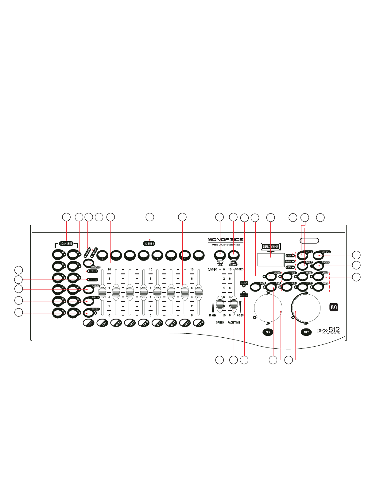
You will find various programming tools, such as 8 universal channel sliders, a
wheel, and LED display indicators for easier navigation of controls and menu
functions. You can control the pan and tilt of different intelligent lighting fixtures using
the same wheel at the same time by means of the wheel programming ability. This
wheel allows the user to assign individual pan and tilt channels for each fixture.
1.4 Glossary of Terms
The following are common terms used in intelligent light programming.
Blackout is a state where the light output of all lighting fixtures is set to 0 or off,
usually on a temporary basis.
Chases can also be called programs. A chase consists of a bunch of scenes
stacked one after another.
DMX-512 is an industry standard digital communication protocol used in
entertainment lighting equipment. For more information read Sections DMX
Primer and DMX Control Mode in the Appendix.
Fade Slider is used to adjust the time between scenes within a chase.
Fixture refers to a lighting instrument or other device you can control, such as a
fogger or dimmer.
MIDI is a standard for representing musical information in a digital format. A MIDI
input would provide external triggering of scenes using a MIDI device, such
as a MIDI keyboard.
Patching refers to the process of assigning fixtures to a DMX channel.
Programs are a collection of scenes stacked one after another. A program can
consist of either a single scene or multiple scenes in sequence.
Scanner refers to a lighting instrument with a pan and tilt mirror.
3

Scenes are static lighting states.
Shutter is a mechanical device in the lighting fixture that allows you to block the
light's path. It is often used to lessen the intensity of the light output and to strobe.
Sliders are also known as faders.
Speed Slider affects the amount of time a scene will hold its state. It is also
considered a wait time.
Stand Alone refers to a fixture's ability to function independently of an external
controller and usually in sync to music, dueto a built in microphone.
2CONTROLS AND CONNECTIONS
2.1 Top Panel
1. SCANNERS BUTTONS
Allows direct selection of the connected devices/fixtures.
2. SCANNERS LEDS
When lit, indicates that the corresponding device/fixture is selected.
3. SCENES BUTTONS
Universal bump buttons representing scene location for storage and selection.
1
2
3
4
5
6
7
8
9
10
11
12
PAG E A
CH1
CH2
CH3
CH4
CH5
CH6
CH7
CH8
0
2
4
6
8
10
0
2
4
6
8
10
0
2
4
6
8
10
0
2
4
6
8
10
10
8
6
4
2
0
0.1/SEC 30 SEC
10 MIN 0 SEC
AUTO
DEL
MUSIC
BANKCOPY
SPEED FADE TIME
8
7
6
5
16
19
15
14
10
2422232120
1 3 4 18 92 29 28 27
2617
11 12 13
612120
4

4. CHANNEL FADERS
Allows adjustment of DMX values. Channels 1-8 are adjusted when the PAGE A
LED is lit and Channels 9-16 are adjusted when the PAGE B LED is lit.
5. PAGE A LED
When illuminated, indicates that Channels 1-8 are available for adjustment.
6. PAGE B LED
When illuminated, indicates that Channels 9-16 are available for adjustment.
7. PAGE SELECT BUTTON
Press to cycle through the pages ofcontrol options. Page A, Page B, and Both
Pages. The PAGE A and PAGE BLEDs illuminate to indicate the selected pages.
8. PROGRAM BUTTON
Press to toggle programming mode on/off. The LED illuminates when
programming mode is active.
9. MUSIC/BANK COPY
When in programming mode, pressing this button issues the Copy command.
Otherwise, pressing this button activates Music mode.
10. LCD DISPLAY WINDOWS
This status window displays pertinent operational data.
11. MODE INDICATOR LEDS
Indicates the operating mode status (Manual, Music, or Auto).
12. BANK UP BUTTON
Function button to traverse Scene/Steps in banks or chases. When the FINE
button is active, pressing this button increases the DMX values.
13. BANK DOWN BUTTON
Function button to traverse Scene/Steps in banks or chases. When the FINE
button is active, pressing this button decreases the DMX values.
14. TAP/DISPLAY BUTTON
During play, pressing this button produces a Tap-Sync. During programming
pressing, this button changes the DMX value displayed in the LCD panel to
percentage values.
15. BLACKOUT BUTTON
Sets the shutter or dimmer value of allfixtures to 0 causing alllight output to cease.
5

16. MIDI/REC BUTTON
Activates MIDI external control and is used to confirm the record/save process.
17. ASSIGN LED
During initial setup, indicates that the controller is in Channel assign mode.
18. AUTO/DEL BUTTON
During programming, pressing this button deletes the current function.
Otherwise, pressing this button activates Auto mode.
19. CHASE BUTTONS
These buttons allow direct access to Chase Memories 1 - 6.
20. SPEED FADER
This slider adjusts the hold or wait time of a scene or a step within a chase.
21. FADE TIME FADER
Also considered a cross-fader, this slider sets the time interval between two
scenes in a chase.
22. FINE BUTTON
Activates 16-bit control of the wheel, resulting in movement being in extremely
small increments. Additionally, while the FINE button is active, the Bank
UP/DOWN buttons will increase and decrease the DMX values by one for either
the wheel or the slider in focus or currently being moved.
23. REVERSE LED
Indicates that Reverse mode is active.
24. PAN/TILT WHEELS
Used to control the pan and tilt movements of a fixture.
25. MODE BUTTON
This multifunction button is used for assigning pan/tilt wheels and channels.
26. OVERRIDE BUTTON
Used to override the fixture settings.
27. FOG MACHINE BUTTON
Pressing this button activates the connected fog machine.
28. FOG MACHINE READY INDICATOR
Indicates that the connected fog machine is heated up and ready to disperse fog/mist.
29. FOG MACHINE HEATING INDICATOR
Indicates that the fog machine is heating up.
6

30. AUDIO INPUT JACK
Direct audio feed for use in sound-active mode
31. MIDI INPUT PORT
The MIDI input is for externaltriggering of Banks and Chases using a MIDI
device.
32. DMX POLARITY SWITCH
May be used to correct signal polarity.
33. DMX OUTPUT CONNECTOR
DMX control signaloutput to DMX devices and/or other controllers.
34. DMX INPUT CONNECTOR
Used totransfer programmed data between two controllers.
35. FOG MACHINE SOCKET
Plug a DMX fog machine into this socket.
36.DC INPUT JACK
DC power connector for use with the included AC adapter.
37. USB LAMP SOCKET
This USB power jack is intended for use with the included USB light. It is just for
power and does not have a data connection of any kind.
38. POWER SWITCH
Turns the controller on and off.
1=Ground
3=Data +
1
2
3
12
3
OFF
ON
POWER
DC 9V-12V
300mA min
MACHINE
DC INPUT
FOG
DMX IN
DMX OUT
DMX OUT
MIDI
LAMP
US B
0.1-1VP-P
AUDIO
DMX Polarity select
1
2
3
1=Ground
2=Data +
30 31 32 33 34 35 36 37 38
7

2. Once everything is connected, plug the included AC adapter into the DC
connector on the back panel. Plug the other end into a nearby AC power outlet.
3. Press the I side of the power rocker switch to turn power ON.
3.1.2 FIXTURE ADDRESSING
This controller is programmed to control 16 channels of DMX per fixture, therefore
the fixtures you wish to control with the corresponding Scanner buttons on the unit,
must be spaced 16 channels apart.
Please refer to your individual fixture's manual for DMX addressing instructions.
The table above refers to a standard dipswitch binary configurable device.
Fixture or Scanner # Default DMX Starting
Address Binary Dipswitch
Settings (Switch to the
ON Position)
1 1 1
2 17 1, 5
3 33 1, 6
4 49 1, 5, 6
5 65 1, 7
6 81 1, 5, 7
7 97 1, 6, 7
8 113 1, 5, 6, 7
9 129 1, 8
10 145 1, 5, 8
11 161 1, 6, 8
12 177 1, 5, 6, 8
3 OPERATING INSTRUCTIONS
3.1 Setup
3.1.1 SETTING UP THE SYSTEM
1. Using DMX cables, connect your intelligent lighting fixtures to the controller, as
specified in the fixture manual(s).
8

2. Simultaneously press the FINE and MODE buttons, release them, then press
them again a second time to access the Channel Assignment mode. The
Assign LED will illuminate in response. The wheel can be reassigned to output
on a different DMX channel.
Note: Simultaneously press the AUTO/DEL and MODE buttons to delete the
channel assignment mode.
3. Press a SCANNER button that represents the fixture for which you would like to
set the pan & tilt.
4.Use the BANK UP and BANK DOWN buttons to select pan/tilt.
5. Press the TAP/DISPLAY button to switch pages.
Note: You can reassign the DMX channel to all controller fader channels.
6. Press and hold the MODE button, then press the SCENES buttons to select the
DMX channel. All LEDs will blink.
7. Press and hold the FINE & MODE buttons to exit.
3.1.4 REVERSE REVIEW
1. Simultaneously press the FINE and MODE buttons to access wheel assignment mode
2. Press a SCANNER button to select a scanner.
3. Simultaneously press the FINE and MODE buttons, release them, then press
them again a second time to exit
3.1.5. WHEEL ASSIGNMENT REVIEW
1. Simultaneously press the FINE and MODE buttons, release them, then press
them again a second time to access the Channel Reverse mode.
2. Press a SCANNER button to select a scanner.
3. Simultaneously press the FINE and MODE buttons to exit.
3.1.3 WHEEL ASSIGNMENT
Because not all intelligent lighting fixtures are alike or share the same control
attributes, the Monoprice 612120 DMX Controller allows you to assign to the
wheel the correct pan and tilt channel for every individual fixture, including 16-bit
channel assignments. It also allows you to reassign physical faders to fixture DMX
channels so that you can combine or unify control of similar or the same attributes
across different types of fixtures.
All wheels can be reassigned to output on a different DMX channel.
Press and hold the PROGRAM button until the LED blinks.
1 .
9

3.1.6 COPY SCANNER
To save time, you can copy the settings from one Scanner to that of another. In
this example, we will review how to copy Scanner 1 to Scanner 2.
1. Press and hold the SCANNER 1 button.
2. While holding the SCANNER 1 button, press and hold the SCANNER2 button.
3. While holding the SCANNER 2 button down, release the SCANNER 1 button.
4. Release the SCANNER 2 button. All SCANNER LED indicators will flash to
confirm the successful copy.
3.1.7 REVERSE CHANNEL OUTPUT
You can permanently reverse the output of any given channel on the controller.
1. Press and hold the PROGRAM button until the LED blinks.
2. Simultaneously press the FINE and MODE buttons to access the channel
assignment mode, then press the SCANNER button.
Note: Simultaneously press the AUTO/DEL and MODE buttons to delete
the reverse channel.
3. Use the BANK UP and BANK DOWN buttons to select pan/tilt.
4. Press the TAP/DISPLAY button to switch between pages.
5.Press and hold MODE button, then press the SCENES buttons to select the
DMX channel. All LEDs will blink.
6.Simultaneously press and hold the FINE and MODE buttons, release them, then
press them again a second time to exit
3.1.8 FADE TIME ASSIGN
You can choose whether the board's fade time during scene execution is
implemented globally, to all output channels, or only to the Pan & Tilt movement
channels. This is relevant because often you will want gobos and colors to change
quickly, while not affecting the movement of the light.
1. Turn OFF the controller.
10
2. Simultaneously hold the MODE and TAP/DISPLAY buttons.
3. While still holding the buttons, turn the controller ON.
4. Press the TAP/DISPLAY button to toggle between the two modes. You can
select either ALL CH, which applies toallchannels, or ONLY X/Y,which
applies to pan & tilt only.
5. Press and hold the MODE button then press the TAP/DISPLAY button to save
the settings. All LEDs will blink toconfirm.

3.2 Operation
3.2.1 MANUAL MODE
Manual mode allows direct control of all scanners. You are able to move them and
change attributes by using the channel faders and wheel. Note that all changes
made while in Manual made are temporary and will not be recorded.
1. Press the AUTO/DEL button repeatedly until the MANUAL LED illuminates.
2. Press a SCANNER button to select that Scanner.
3. Move the wheel and faders to manually change fixture attributes.
4. Use the PAGE SELECT button to switch between fader control of Channels 1-8
and fader control ofChannels 9-16.
5. Press the TAP/DISPLAY button to toggle the LCD display between DMX values
(0-255)and percentages (0-100).
3.2.2 REVIEW SCENE OR CHASE
This instruction assumes that you have already recorded Scenes and Chases on
the controller. Otherwise, skip this section and go to section 3.3 Programming.
1. If the controller is not in Manual mode, enable Manual mode by following the
instruction in section 3.2.1.
2. Use the BANK UP and BANK DOWN buttons to select one of the 30 Banks.
3. Select a SCENE button corresponding to the Scene you want to review.
11
4. Move the wheels and faders to change fixture attributes.
3.2.3 REVIEW SCENE OR CHASE
This instruction assumes that you have already recorded Scenes and Chases on
the controller. Otherwise, skip this section and go to Programming.
1. If the controller is not in Manual mode, enable Manual mode by following the
instruction in section 3.2.1.
2. Press one of the six CHASE buttons.
3. Press the TAP/DISPLAY button to view the step number on the display.
4. Press the BANK UPand BANK DOWN buttons to review allscenes in the Chase.

3.3 Programming
A Program (Bank) is a sequence of different Scenes (or steps), that will be
performed one after another. Programs can consist of up to 8 Scenes each.
3.3.1 ENTERING PROGRAM MODE
1. Press the PROGRAM button repeatedly until the LED blinks.
3.3.2 CREATE A SCENE
A scene is a static lighting state. Scenes are stored in banks. There are 30 bank
memories on the controller and each bank can hold 8 scene memories. The
controller can save 240 scenes total.
1. Press the PROGRAM button repeatedly until the LED blinks.
Note: If the Blackout LED is illuminated, press the BLACKOUT button to
deselect it.
2. Position the SPEED and FADE TIME sliders all the way down.
3. Select the SCANNERS you wish to include in your scene.
Note: You can select more than one fixture.
4. Compose the Scene by moving the sliders and wheel.
12
Note: You can access Channels 9-16 by pressing the PAGE SELECT button.
This is necessary for fixtures that use more than 8 channels of control.
5. Tap the MIDI/REC button.
6. Choose a BANK (01~30) to change, if necessary.
Note: There are 8 scenes available in every Bank.
7. Select a SCENES button to store.
Note: All LEDs will flash toconfirm. The LCD display will now indicate the Scene
number and Bank number in use.
8. Repeat steps 3 through 7 as necessary. Up to 8 scenes can be recorded in a Program
9. To exit Program mode, hold the PROGRAM button.
Tip! Press the FINE button, activate the wheel or slider by moving it, then usethe
BANK UP and BANK DOWN buttons to change the values in increments of1.

3.3.3 RUNNING A PROGRAM
1. Use BANK UP and BANK DOWN buttons to change Program banks, as necessary.
Note: If the Blackout LED is illuminated, press the BLACKOUT button to
deselect it.
2. Press the AUTO/DEL button repeatedly until the AUTO LED turns on.
3. Adjust the Program speed via the SPEED fader and the loop rate via the FADE
TIME fader.
4. Alternatively, you can tap the TAP/DISPLAY button twice. The time between
the two taps will become the time between SCENES (up to 10 minutes).
This is also called "Tap-Sync".
3.3.4 CHECK PROGRAM
13
1. Press and hold the PROGRAM button until the LED blinks.
2. Use the BANK UP and BANK DOWN buttons to select the Program bank to review.
3. Press the SCENES buttons to individually review each scene.
3.3.5 EDITING A PROGRAM
Scenes will need to be modified manually.
1. Press and hold the PROGRAM button until the LED blinks.
Note: Ifthe Blackout LED isilluminated, press the BLACKOUT button to deselect it.
2. Use the BANK UP and BANK DOWN buttons to change Program banks if necessary.
3. Use the SCANNERS buttons to select the desired fixture.
4. Adjust and change fixture attributes using the channel faders and wheels.
5. Press the MIDI/REC button to prepare the save.
6. Select the desired SCENES button to save.
3.3.6 COPY A PROGRAM
1. Press and hold the PROGRAM button until the LED blinks.
2. Use the BANK UPand BANK DOWN buttons to select the Program bank you will copy.
Note that the allscenes in the Program bank (up to 8) will be copied.
3. Press the MIDI/REC button to prepare the copy.
4. Use the BANK UP and BANK DOWN buttons to select the destination Program bank.
5.Press the MUSIC BANK COPY button to execute the copy. All LEDs on the controller
will blink toconfirm.

14
3.4 Chase Programming
A chase is created by using previously created scenes. Scenes become steps in a
chase and can be arranged in any order you choose. It is highly recommended that,
prior to programming chases for the first time; you delete all chases from memory.
See 3.4.9 Delete All Chase Programs for instructions.
3.4.1 CREATE A CHASE
A Chase can contain up to 240 scenes as steps. The term steps and scenes are
used interchangeably.
1. Press the PROGRAM button until the LED blinks.
2. Press the CHASE button you wish to program.
3. Change the BANK as necessary to locate a Scene.
4. Select the SCENE to insert.
5. Tap the MIDI/REC button to store the Scene.
6. Repeat steps 3 through 5 to add additional steps in the Chase. Up to 240 steps
can be recorded.
7. Press and hold the PROGRAM button to save the Chase.
3.4.2 RUNNING A CHASE
1. Press a CHASE button then press the AUTO/DEL button.
2. Adjust the Chase speed by tapping the TAP/DISPLAY button, waiting the
desired delay period, then tapping the TAP/DISPLAY button again a second
time. The time interval between the two taps will become the Chase Speed (up
to 10 minutes).
3.4.3 CHECKING A CHASE
1. Press and hold the PROGRAM button until the LED illuminates.
2. Select the desired CHASE button.
3. Press the TAP/DISPLAY button to switch the LCD display to steps.
4. Review each scene/step individually by using the BANK UP and BANK DOWN
buttons.

3.4.4 COPY BANK INTO CHASE
1. Press and hold the PROGRAM button to enter Programming mode.
2. Press the desired CHASE button.
3. Use the BANK UP and BANK DOWN buttons to select the BANK to be copied.
4. Press MUSIC/BANK COPY button to prepare the copy.
5. Press the MIDI/REC button to copy the bank. All LEDs will blink to confirm.
3.4.5 COPY SCENE INTO CHASE
1. Press and hold the PROGRAM button to enter Programming mode.
2. Press the desired CHASE button.
3. Use the BANK UP and BANK DOWN buttons to select the BANK that contains
the scene to be copied.
4. Press the SCENE button that corresponds to the scene to be copied.
5. Press the MIDI/REC button to copy the scene. All LEDs will blink to confirm.
3.4.6 INSERT SCENE INTO A CHASE
1. Press and hold the PROGRAM button to enter Programming mode.
2. Press the desired CHASE button.
3. Press the TAP/DISPLAY to switch the LCD display to steps view.
15
4. Use the BANK UP and BANK DOWN buttons to navigate steps and locate
the insert point ofthe new scene. The display will show the step number
after which the scene will be inserted.
Example: If inserting a scene between Steps 5 and 6, the display should show
STEP05.
5. Press the MIDI/REC button to prepare the insert.
6. Use the BANK UP and BANK DOWN buttons to locate the SCENE.
7. Press the SCENE button that corresponds to the scene to be inserted.
8. Press the MIDI/REC button to insert the scene. All LEDs will blink to confirm.

3.4.7 DELETE A SCENE IN A CHASE
1. Press and hold the PROGRAM button to enter Programming mode.
2. Press the desired CHASE button that contains the scene to be deleted.
3. Press the TAP/DISPLAY button to switch the LCD display to steps.
4. Use the BANK UPand BANK DOWN buttons to select the scene/step to be deleted.
5. Press AUTO/DEL button to delete the step/scene. All LEDs will blink to confirm.
3.4.8 DELETE A CHASE
1. Press and hold the PROGRAM button to enter Programming mode.
2. Press the CHASE button to be deleted.
3. Simultaneously press the AUTO/DEL button and the CHASE button from the
previous step to delete the chase. All LEDs will blink to confirm.
3.4.9 DELETE ALL CHASE PROGRAMS
WARNING! This procedure will result in the irrevocable loss of all chase step
memory. However, the individual scenes and program banks will be preserved.
16
1. Turn the controller OFF.
2. Simultaneously press and hold the BANK DOWN and the AUTO/DEL buttons.
While holding these buttons down, turn the controller ON.
3. All LEDs will blink to confirm.
3.5 Scene Programming (Steps)
3.5.1 INSERT A SCENE
1. Press and hold the PROGRAM button to enter Programming mode.
2. Press the desired CHASE button.
3. Press the TAP/DISPLAY button to switch the LCD display to steps view.
4. Use the BANK UP and BANK DOWN buttons to navigate steps and locate the
insert point of the new scene. The display will show the step number after
which the scene will be inserted.
Example: If inserting a scene between Steps 5 and 6, the display should show
STEP05.
5. Press the MIDI/REC button to prepare the insert.
6. Use the BANK UP and BANK DOWN buttons to locate the Scene.
7. Press the SCENE button that corresponds to the scene to be inserted.
8. Press the MIDI/REC button to insert the scene. All LEDs will blink to confirm.

3.5.2 COPY A SCENE
1. Press and hold the PROGRAM button to enter Programming mode.
2. Use the BANK UP and BANK DOWN buttons to select the Bank that contains the
scene to be copied.
3. Press the SCENE button that corresponds to the scene to be copied.
4. Press the MIDI/REC button to copy the scene.
17
5. Use the BANK UP and BANK DOWN buttons to select the BANK destination that
contains the scene memory to record to.
6. Press the desired SCENE button to complete the copy. All LEDs will blink to confirm.
3.5.3 DELETE A SCENE
Note: When deleting a scene the physical location is not removed, however,
all 192 DMX channels available to the scene will be set to value 0.
1. Press and hold the PROGRAM button to enter Programming mode.
2. Use the BANK UP and BANK DOWN buttons to select the BANK that contains
the scene to be deleted.
3. Press the AUTO/DEL button.
4. Press the SCENE button that corresponds to the scene you want to delete.
All LEDs will blink toconfirm.
3.5.4 DELETE ALL SCENES
WARNING! This process is irreversible! All scenes with data will be set to 0.
1. Press and hold the PROGRAM button and the BANK DOWN button. While
holding the buttons down, turn the controller OFF.
2. Turn the controller back ON.
3.6 Playback
3.6.1 RUNNING IN SOUND-MODE
In Sound mode, programs will be triggered by sound, using the controller's built-in
microphone.
1. Press the MUSIC BANK COPY button repeatedly until the MUSIC LED turns on.
2. Use the BANK UP and BANK DOWN buttons to select the program BANK to run
in sound active mode.

3. Alternatively you can press a single CHASE button or several CHASE buttons in
sequence and all selected chases will loop in the order selected.
Note: Multiple selected chases will loop and run in the order originally selected.
4. Use the FADE TIMER to adjust the duration time.
3.6.2 RUNNING IN AUTO-MODE
Note: In Auto mode, programs will be triggered by the controller's FADE TIME and
SPEED fader settings.
1. Press the AUTO/DEL button repeatedly until the AUTO LED turns on.
2. If a CHASE button is not pressed, the controller will automatically run a BANK
program.
3. Use the BANK UP and BANK DOWN buttons to change the BANK programs.
4. Alternatively you can press a single CHASE button or several CHASE buttons in
sequence. All selected chases will loop in the order selected.
5. You can adjust the time between steps by moving the SPEED fader and the
duration of the step by moving FADE TIME the fader.
3.6.3 RUN MULTIPLE CHASES SIMULTANEOUSLY
IMPORTANT! To avoid conflict between scenes running simultaneously that
control the same fixture attributes, consider creating individual color and gobo
chases.
1. Press and hold the AUTO/DEL button.
2. While holding down the AUTO/DEL button, press and release each CHASE you
want to run simultaneously.
3.6.4 BLACKOUT
Press the BLACKOUT button to set the lighting output of all fixtures to 0 or OFF.
18

3.7 MIDI Input Operation
The controller will onlyrespond to MIDI commands on the MIDI channel to which
it is set. All MIDI control isperformed using "Note On" commands. All other MIDI
instructions are ignored. To stop a chase, send the BLACKOUT note (MIDI Note
126, see table below).
1.Press and hold the MIDI/REC button for about 3 seconds.
2. Use the BANK UPand BANK DOWN buttons to select the MIDI control channel (1-16).
Note: This isthe Channel on which the controller will receive MIDI "Note On" commands.
3. Press and hold the MIDI/REC button for 3 seconds to save the settings.
4. To release MIDI control, repeat the above process, but press any other button
except the BANK buttons in Step 2.
MIDI Note Function MIDI Note Function
00 to 07 Scenes 1-8 in BANK 1 88 to 95 Scenes 1-8 in BANK 12
08 to 15 Scenes 1-8 in BANK 2 95 to 103 Scenes 1-8 in BANK 13
16 to 23 Scenes 1-8 in BANK 3 104 to 111 Scenes 1-8 in BANK 14
24 to 31 Scenes 1-8 in BANK 4 112 to 119 Scenes 1-8 in BANK 15
32 to 39 Scenes 1-8 in BANK 5 120 Chase 1
40 to 47 Scenes 1-8 in BANK 6 121 Chase 2
48 to 55 Scenes 1-8 in BANK 7 122 Chase 3
56 to 63 Scenes 1-8 in BANK 8 123 Chase 4
64 to 71 Scenes 1-8 in BANK 9 124 Chase 5
72 to 79 Scenes 1-8 in BANK 10 125 Chase 6
80 to 87 Scenes 1-8 in BANK 11 126 BLACKOUT
3.8 Data Transfer
It is possible to transfer the programs stored in one Monoprice 612120 DMX
Controller to another by performing the following steps:
1. Use a DMX cable to connect the output ofthe source controller to the input of
the destination controller.
2. Turn the source controller OFF. Press and hold down the SCANNER 2,
SCANNER 3, and SCENE 1 buttons. While holding down the buttons, turn the
controller ON. The LCD display will show TRANSMIT, indicating that it is ready
to transmit data.
19
3. Turn the destination controller OFF. Press and hold down the SCANNER 8,
SCANNER 9, and SCENE 2 buttons. While holding down the buttons, turn the
controller ON. The LCD display will show RECEIVE, indicating that it is ready to
receive data.
4. Both units are now ready to transmit and receive. Simultaneously press the
SCENE 7 and SCENE 8 buttons on the source controller to begin the transmission.

4 APPENDIX
4.1 DMX Primer
There are 512 channels in a DMX-512 connection. Channels may be assigned in
any manner. A fixture capable of receiving DMX 512 will require either one channel
or a number of sequential channels. The user must assign a starting address on the
fixture that indicates the first channel reserved in the controller.
There are many different types of DMX controllable fixtures and they all may vary in
the total number of channels required. Choosing a start address should be planned
in advance. Channels should never overlap. If they do, this will result in erratic
operation of the fixtures whose starting address is set incorrectly. You can however,
control multiple fixtures of the same type using the same starting address as long as
the intended result is that of unison in movement or operation.In other words, the
fixtures will be slaved together and will all respond exactly the same.
DMX fixtures are designed to receive data through a serial Daisy Chain. A Daisy
Chain connectionis one in which the DATA OUT of one fixture connects to the DATA
IN of the next fixture. The order in which the fixtures are connected is not important
and has no effect on how a controller communicates to each fixture. Use an order that
provides for the easiest andmost direct cabling. Connect fixtures using shielded two
conductor twistedpair cable with three pin XLR male to female connectors. The shield
connection is pin 1, while pin 2 is Data Negative (S-) and pin 3 is Data positive (S+).
4.2 DMX Termination
The output of the last fixture in the daisy chain must be terminated with a DMX
Terminator. To make a DMX terminator, solder a 120-ohm resistor between pins
2 and 3 of an XLR connector. Plug the DMX Terminator into the output of the last
fixture in the daisy chain.
20
DMX-OUTPUT DMX-OUTPUT
Occupation of theXLR-connection:
XLRmounting-socket:
1. Ground
2. Signal(-)
3. Signal(+)
1. Ground
2. Signal(-)
3. Signal(+)
XLRmounting-plug:
3 3
2 21 1
120ohm
PIN3
PIN2
3
2 1
Table of contents
Other Monoprice Recording Equipment manuals

Monoprice
Monoprice DARK MATTER 44708 User manual

Monoprice
Monoprice SS-6 User manual

Monoprice
Monoprice SS-4 User manual

Monoprice
Monoprice Stage Right STi12 User manual

Monoprice
Monoprice SSVC-4.1 User manual

Monoprice
Monoprice MP-SS4 User manual

Monoprice
Monoprice SS2V70 User manual

Monoprice
Monoprice 604830 User manual
Popular Recording Equipment manuals by other brands

PMFoundations
PMFoundations ER-808 Tom Module Assembly guide

Cisco
Cisco 4492R Regulatory compliance and safety information

Roland
Roland S-330 Supplemental notes

Digital Voice Systems
Digital Voice Systems AMBE-2000 supplementary guide

Hagerman Audio Labs
Hagerman Audio Labs Trumpet MC manual

Yamaha
Yamaha TG300 owner's manual