Totai TOTG4502CB User manual

Issue 1-2019
Safe Appliance
LP Gas Safety Association
Distributed by: D.K.Gas Appliances (Pty) Ltd
email: [email protected]. Website: www.totai.co.za
PO Box 34191 Erasmia 0023
Safe Appliance
LP Gas Safety Association
This appliance complies with the requirements of SANS 1539.
LPGSASA Permit number: 1051-203/1-RSA-17-A
Distributed by: D.K.Gas Appliances (Pty) Ltd
PO Box 34191 Erasmia 0023
email: [email protected]. Website: www.totai.co.za
Read these instructions carefully before installing and using
the appliance, and retain them for future reference
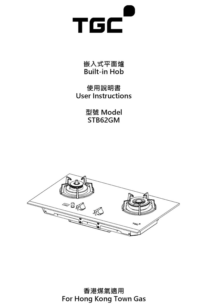
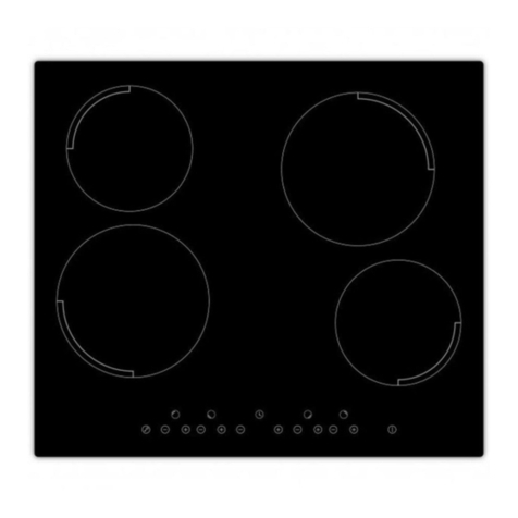
TOTAI 4 Burner Gas Hob
Model TOTG4502CB
Instructions for installation and use

Important information for the user
Read these instructions carefully before using the appliance and retain them for future
reference. This appliance consumes oxygen when in use and it is important that it is only used in
a well ventilated area for the efficient performance of the appliance and for the safety of the
occupants of the area.
This appliance may only be installed by a registered LP Gas installer. All registered
installers are issued with a card carrying their registration number. Ask to be shown the card
before allowing the installation work to commence and make a note of the Installer registration
number. Upon completion of the installation, the installer is required to explain the operational
details of the appliance together with the safety instructions. You will be asked to sign
acceptance of the installation and be provided with a completion certificate. You should only
sign for acceptance of the installation when the installation is completed to your satisfaction.
Note that your invoice is required in the event that you wish to make a guarantee claim.
The appliance has been designed specifically for use with LPG and may not be used with Towns
Gas or Natural Gas.
Read these instructions carefully before commencing the installation.
Important information for the installer.
This appliance may only be installed by a LP Gas installer registered by SAQCC Gas, the
government appointed registering body for all gas installers. The appliance must be installed in
accordance with the requirements of SANS 10087-1 and any fire department regulations and/or
local bylaws applicable to the area. If in doubt, check with the relevant authority before
undertaking the installation. Upon completion of the installation you are required to fully explain
and demonstrate to the user the operational details and safety practices applicable to the
appliance and the installation.
For detailed installation instructions refer to section 8 & 9 of this manual.
Model Number
TOTG4502CB
Gas Type: LP Gas
Operating pressure
2,8 kPa
Total gas consumption: 545 g/h
Small Burners (1)
Jet size:0,50mm
Gas consumption: 73g/h
Medium Burner (2)
Jet sizs:0.65mm
Gas consumption: 127 g/h per burner
Large Burner (1)
Jet size 0,85mm
Gas consumption: 218 g/h
Technical data
Thank you for purchasing your new Totai Gas Hob manufactured to the highest standards
and fully tested in South Africa to ensure compliance with the South African Standard. This
appliance is designed to give the user years of trouble free and efficient service. Please read
the following instructions carefully. It is important to note that this appliance must be installed
by a registered LP gas installer as indicated below. The manufacturer and /or its agents and
distributors will not be held responsible for injuries or damages caused by faulty or incorrect
installation or use of the appliance.
2 7
Burner cap
Burner head
Jet
Grid
Ignitor location
Thermocouple Sensor
Ignitor
Fig 1
Clamp Worktop
Hob
Retaining Screw
Fig 3
Fig 1 is a typical Burner assembly showing how a burner has is located over the jet assembly
and next to the insulated ignitor post and thermocouple sensor (Flame Failure device). When
removing and replacing the burner heads take care not to knock or damage the ignitor or
thermocouple. When removing and replacing the burner heads note the original positions to
make sure they that correctly placed. Care must also be taken during cleaning of the hob.
The hob is fitted with a Flame Failure device. This is a safety feature such that in the event of a
loss of flame on any burner the gas supply will shut down
1
2
4
3
1
2
3
4
Fig 4
Identification of the burner
control knob to each burner
Fig.2
Battery Box
Positive
Terminal Negative
Terminal

6 3
·This model requires a low pressure 2,8 kPa LPG Regulator that complies with the requirements of
SANS 1237 to be fitted to the gas cylinder. Ensure that you obtain the correct regulator for the type of
cylinder used with the appliance. Cylinders suitable for use with the appliance are 9kg or greater. Do
not connect the appliance directly to a cylinder with a hose. It is dangerous to do so
·These appliances are fitted with a flame failure device on the cooker burners and therefore may be
connected to a fixed pipework system.
·Ensure that the gas cylinder is fitted or changed in a well-ventilated location, away from any sources of
ignition, such as naked flames and away from other people.
·In the event of a burnback, where the flame burns back and ignites at the jet, immediately turn off the
gas supply by firstly closing the control valve on the gas cylinder or ,where the cylinder is outside , the
isolation valve and then the appliance burner valve. Wait 1 to 2 minutes and light the affected burner in
the normal manner. If the burnback re-occurs call a service technician to examine the appliance and
do not use it until it has been certified as safe to do so.
1. General
·Where a flexible hose is used it hose must comply with the requirements of SANS 1156-2. The hose
must be clamped with a suitable hose clamp at both ends. Note: The hose and regulator are not
supplied with the Totai Hobs. Contact your local gas dealer to purchase the correct hose and regulator.
2. Safety Information
·The hose and the seal on the regulator must be checked for wear or damage before every use and
before connecting to the gas cylinder .
·Ensure the appliance is used away from flammable materials. Minimum safe distances are: above the
appliance 600 mm, at the rear and sides 500 mm.
·Do not place the appliance near doors and windows in order to avoid the possibility of draughts
affecting the burners
·Do not use an appliance that is leaking, damaged or which does not operate properly.
·Keep gas cylinders away from heat and flame.
·If there is a leak on your appliance (smell of gas), check for a gas leak as indicated below.
·Before testing for a leak firstly check that the regulator seal is in place and in good condition. Replace if
in doubt. Also check that the hose clamps on the regulator and the appliance are in place and properly
tightened. Examine the hose for signs of splitting or any other type of damage or wear. Replace if in
doubt.
·When satisfied that the above points are all in order then follow the steps below to check for a leak. Do
not try to detect leaks using a flame, use soapy water.
·Connect the cylinder to the appliance, open the cylinder valve and with the appliance valves in the
closed position, check for a gas leak as indicated below.
·If a gas leak persists return the product to your gas dealer for inspection and/or repair.
·In the event of a gas leak or smell of gas in the house or room in which the appliance is installed, close
the isolation or emergency shut off valve and open all the door and windows to ventilate the area. Do
not use any device with a flame, or turn any electrical switch on or off until the area is clear of gas and
the leak has been fixed by a qualified technician.
·Do not modify the appliance. Do not use it as a heater.
·During use, parts of the appliance will become hot. Avoid touching hot parts with bare hands. The use
of oven type gloves is recommended.
·Keep young children away from the appliance at all times.
·Hot oil and fats are flammable, use them very carefully. In the event of a fire involving hot oil or fats, turn
all the control knobs to the off position and extinguish the flames by smothering them with a pot lid or a
wet towel. Never throw water onto the flames as this will not extinguish them and may even
cause the flames to spread.
·To check for a gas leak, brush all the connection joints with soapy water. If bubbles form then there is a
gas leak. Immediately turn off the gas supply firstly by closing the control valve on the gas cylinder and
then the appliance valve, check that all the connections are properly tightened. Re-check with soapy
water.
Minimum clearance
each side 300 mm
View from front of hob
indicating the minimum
side clearances
View from side of hob in-
dicating the minimum front
and rear clearances
Minimum clearance
front and rear 50 mm
Fig 9
·Fig 9 shows the minimum
clearances for the sides, front and
rear of the appliance. It is important
for the safe operation of the
appliance that these minimum
clearances are observed.
·Now turn the hob up the correct
way and place it in the pre cut
opening in the work top ensuring
that it is centrally placed and that
the sealing strip is still in position
and is not pinched or trapped (see
Fig. 6)
·Now mount the four clamps (see
Fig 3) and tighten using the screws
provided. Do not over tighten.
·The unit is now ready to connect to
the gas supply
·To mount the hob in position, first
remove the grids , burner caps and
burner bodies from the hob. Turn
the hob upside down and rest it on
a firm flat surface. Apply the sealing
strip provided (see Fig 6) and fix
into position.
·The connection between a rigid metal gas supply pipe and the flexible hose must be made using a
proper gas fitting. The side of the fitting that connects to the metal pipe should preferably be a
compression fitting and the side that connects to the flexible hose should have a hosetail of the
form shown in Fig 7.
9. Gas connection information
·It the hob is installed over an oven fitted in the space below the worktop then a rigid pipe shall be
used to supply the gas. A flexible hose is not permitted under these circumstances.
·A mechanical fitting using a flared fitting using a rigid pipe
·A rigid metal gas supply pipe is the preferred method. If the circumstances of installation make the
use of a rigid pipe difficult then the maximum length of flexible hose allowed is 1,5 metres. When
using flexible hose ensure that it cannot come into contact with hot surfaces
·A mechanical compression gas fitting using a rigid pipe. Note that water fittings are not
allowed.
·This appliance requires a gas supply pressure of 2,8 kPa. A regulator that complies with SANS
1237 must be installed.
·The gas connection may be one of the following types:
·A hose connection using a flexible hose clamped to the hosetail (provided with the hob).See
Fig 7.
·The gas supply pipeline must be accessible over its complete length. This is particularly important
where a flexible hose is used.
·All joints must be checked for leaks after installation and before use. To check for leaks, apply a
soapy water solution with a brush or spry to all the joints in the system with the gas supply turned
on. Make sure the burner control valves are in the off position when doing this.

45
·Use only genuine Totai spares. These are available from your local gas supplier or directly from
the distributor. The contact details for the distributor are on the back page of this booklet.
9.Spares
3. Ventilation requirements.
·The gas hob is an unflued appliance and as such it is important from a safety perspective to
supply fresh air into the room in which the appliance is used. It is recommended that this is
achieved by means of a permanent opening such as an air brick, or a opening window that is kept
in an open position whilst the appliance is being used.
·Make sure that the area behind the hob is kept clear and that there are no flammable materials above
the hob.
5. Lighting the Burners
Large burner: 240mm-260 mm dia
·This will ensure that you will achieve the best cooking efficiency. If the flame appears to extend up
the sides of the pot either place the pot on a larger burner or reduce the flame height by adjusting
the required burner control knob. The small burner is ideal for simmering.
7. Cleaning the gas hob
4. Preparing the appliance for use
·Indirect ventilation is also allowed by taking air from rooms adjacent to the one to be ventilated.
·Remove all packing materials and protective film, where used
·Ensure that the burners and burner caps are correctly fitted into their specific locations
·Repeat the above process to ignite the other burners as required.
·Turning the control knob in a clockwise direction from the mid position will again reduce the flame level
and if the knob is turned fully in a clockwise direction to the Off position it will shut down the burner.
6. Using the gas hob
·Do not use any abrasive cleaning products on the hob as this will scratch the surface finish. It is normal
practice to remove the Pot grids for cleaning and to use a hot soapy water solution to remove any
spillage residues.
8.Servicing and maintenance
·There are no preset service or maintenance intervals for this appliance. If the appliance is cleaned
after every use, it should give years of trouble free service without needing any repairs or
servicing.
·Check that the pot support grids are in place.
·To light the burners push in and turn the control knob of the burner you wish to light in an anti clockwise
direct to the mid position. (see Fig.8) This will generate the automatic ignition spark causing the burner
to ignite.
·To adjust the flame to the required level, turn the burner control knob further in an anti clockwise
direction to reduce the flame. If turned fully in this direction, the flame will continue to burn at the
simmer position. Turning the control knob back to the mid position will give the maximum flame level.
·When cooking always use the burner that suits the pot size. For the most effective use of the burners
use the recommended pot sizes indicated below:
Medium burner; 200mm-240mm dia
·Note that each burner is fitted with a flame failure sensor which will shut off the gas supply if the burner
flame goes out. After lighting the burner hold the control knob in the pressed in position for 5-10
seconds to allow the flame failure sensor to function correctly, If the flame goes out when the knob is
released, repeat the light procedure and hold the control knob in for a few more seconds
·The power for the automatic spark ignition is provided by a Type D 1,5v dry cell battery(see Fig 2). The
battery box is on the underside on the hob situated on the front edge. It has a hinged lid for easy
access. It is recommended to replace the battery every 6 months
Small burner: 100mm-140 mm dia
Fig 6
Sealing strip
Fig 7
LPG Flexible hose
Hose Clamp
Hosetail
Sealing
Washer
10.1 Fitting instructions
·If a shelf is fitted to the space below the hob it
is important that this be placed at least
150mm below the underside of the hob
·This LP Gas hob may only be installed by a
registered gas installer.
·Before installing the appliance, make sure
that the LP Gas supply is capable of
delivering the required quantity of LP Gas at
the operating pressure shown in the table on
page 2.
·The LP Gas hobs covered by this instruction
manual are for domestic use only and may
not be installed or used for commercial
applications.
·It is important to note that the gas hob is an
unflued gas appliance and as such it may
only be installed in a well ventilated area. It
uses oxygen, and lack of ventilation may
cause oxygen depletion which could
endanger the life of the occupants of the area
in which the gas hob is installed.
·The surface in which the gas hob is mounted
and installed shall be not less than 30mm
thick and shall be of a heat resistant non
combustible material.
10.Installer information
·It is essential that the cut out in the mounting
surface is shown in Fig 5 and that a
minimum clearance of 300mm on the left and
right hand sides on the hob be established.
The 300mm clearance requirement also
applies to the walls adjacent to the appliance
(see fig 9). See also the cardboard template
that is supplied with the appliance to aid in
placing the cut out in the correct position in
the mounting surface.
·Note: After installation and before handing
over the appliance to the user. Check the
min. flame setting on all the burners. This can
be individually adjusted by inserting a small
flat blade screwdriver into the hole in the
control valve spindle for each burner and
turning it in a clockwise or anti clockwise
direction to increase or decrease the flame as
required. Once set this does not require
further adjustment by the user.
500 mm
553 mm
600 mm
473 mm
Fig 5
Worktop
Take note of the minimum clearances for the
front, back and sides as shown on Fig 7
Off
Low
flame
Ignite and
high flame
Fig 8
Other Totai Hob manuals
