Totai 16/DK1021A User manual

For Outdoor Use Only
Important: Read these instructions for use carefully so as to familiarise yourself with
the appliance before connecting it to its gas container. It is also important to follow the
assembly instructions. Keep these instructions for future reference
LPGSASA PERMIT NUMBER 1051-XX-RSA-12/A
Safe Appliance
LP Gas Safety Association
INSTRUCTIONS FOR USE AND ASSEMBLY
PRECAUTIONS
·Leak test all connections after each cylinder
refill
·Never check for leaks with a match or open
flame
·Do not store or use petrol or other flammable
vapours and liquids in the vicinity of this or
other any other appliance
·Any LPG cylinder not connected for use shall
not be stored in the vicinity of this or any other
appliance
WARNING
HAZARDOUS FIRE OR EXPLOSION MAY
RESULT IF INSTRUCTIONS ARE IGNORED
It is the consumer’s responsibility to see that the
heater is properly assembled, installed, and
taken care of. Failure to follow instructions in this
manual could result in serious bodily injury
and/or property damage
FOR YOUR SAFETY
IF YOU SMELL GAS:
·Turn of gas supply at the cylinder.
·Extinguish all naked flames
·Do not operate any electrical appliances.
·Ventilate the area.
·Check for leaks as detailed in this manual
·If odour persists, contact your dealer or gas
supplier immediately.
Model: 16/DK1021A & 16/DK1022A
Outdoor Patio Heater

- 2 -
PLEASE READ THE FOLLOWING SAFETY GUIDELINES BEFORE OPERATION
CAUTION
ŸDo not use the patio heater indoor, as it may cause personal injury or property damage.
ŸThis outdoor heater in not intended to be installed on recreational vehicles and/or boats.
ŸInstallation and services should only be a done qualified service person.
ŸImproper installation, adjustment, alteration can cause personal injury or property damage.
ŸDo not attempt to alter the unit in any manner.
ŸNever replace or substitute the regulator with any regulator other than the factory recommended replacement.
ŸDo not store or use petrol or other flammable vapours with, in, or near the heater.
ŸThe complete gas system and all connections should be inspected for leaks before use, and at least annually by a
qualified service technician.
ŸAll leak tests should be done with a soapy water solution. If there is a leak then bubble will form at that point. Never
use an open flame to check for gas leaks.
ŸDo not use the heater until all connections have been leak tested.
ŸIf you smell gas, turn off the gas supply at the cylinder and check all connections for leaks using a soapy water
solution. Tighten the leaking connection and then recheck again with a soapy water solution. If you cannot find the
source of the leak, call a qualified service technician and do not use the appliance until it has been declared safe to
do so.
ŸDo not move or transport the heat whilst it is operating.
Ÿdo not touch or move the heater after it has been turned off until it has cooled down.
ŸDo not cover up the ventilation opening in the cylinder compartment.
ŸDo not paint the radiant screen, control panel or top canopy reflector.
ŸControl compartment, burner and circulation air passageways must be kept clean.
ŸFrequent cleaning may be necessary as required.
ŸThe LPG Cylinder should be turned off when the heater is not in use.
ŸCheck the heater immediately if any of the following occurs:
- The heater does not reach temperature.
- The burner makes popping noises during operation (a slight noise is normal when the heater is extinguished).
- A smell of gas in conjunction with yellow tipping o flames.
ŸAny guard or other protective device removed for servicing must be replaced before using the heater.
ŸAdults and children should stay away from high temperatures areas of the heater to avoid burns of clothing igniting.
ŸChildren should be carefully supervised when near the heater
ŸAlways change the cylinder in well ventilated areas and away from any sources of ignition e.g. open flames.
ŸCheck that the regulator seal is in place and in good condition whenever the cylinder is changed.
ŸNever obstruct or cover the ventilation apertures in the cylinder housing.
ŸAlways close the cylinder control valve when the heater is not in use.
ŸIn the event of a gas leakage do not use the heater. Call a qualified service technician to examine the heater before
using the heater.
ŸCheck the condition of the flexible gas hose at least once per year for sign of cracking, bulging, splitting of other
signs of deterioration. Replace if necessary.
ŸIn the event of a burn-back, where the flame burns back to the jet, immediately turn off the gas supply at the control
valve on the panel. After ensuring the flame is extinguished, re-light the appliance in the normal manner. Should the
appliance again burn back, close the control valve and call a service technician. Do not use the appliance again
until the service technician has declared that it is safe to do so.
- 3 -
ŸUse a 9 kg LPG cylinder only
ŸThe hose must comply with the requirements of SANS 1156-2 or BS 2312
ŸA dented, rusted or damaged LPG cylinder may be hazardous and should not be used
ŸNever use a cylinder with a damaged valve connection
ŸThe cylinder valve must have a horizontal outlet with a G5/8 left hand thread to suit the regulator
ŸNever connect the cylinder directly to the heater . A regulator must always be used
ŸThe regulator must comply with the requirements of SANS 1237.
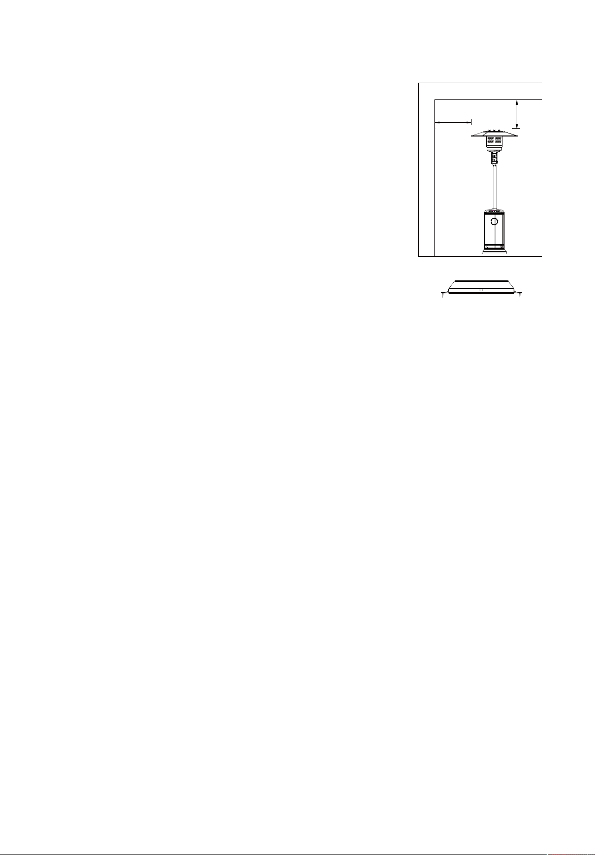
ŸThe heater is for outdoor use only. Always ensure that adequate fresh air
ventilation is provided.
ŸAlways maintain proper clearance to combustible materials, i.e. top 100 cm
and sides 100 cm minimum.
ŸHeater must be placed on level firm ground.
ŸNever operate heater in an explosive atmosphere like in areas where petrol or
other flammable liquids or vapours are stored.
ŸTo protect heater from strong wind, anchor the base securely to the ground
with screws.
HEATER STAND AND LOCATION
GAS REQUIREMENTS
LEAKAGE TEST
ŸGas connections on the heater are leak tested at the factory prior to shipment. A complete gas tightness
check must be performed at the installation site due to possible mishandling in shipment or excessive
pressure being applied to the heater.
ŸMake a soap solution of one part liquid detergent and one part water. The soap solution can be applied with a
spray bottle, brush or rag. Soap bubbles will appear in case of a leak.
ŸThe heater must be checked with a full cylinder.
ŸMake sure the safety control valve is in the OFF position.
ŸTurn the gas supply ON.
ŸIn case of a leak, turn off the gas supply. Tighten any leaking fittings, then turn the gas supply on and re-
check.
ŸNever leak test while smoking.
CEILING
W A L L
100 cm
100 cm
Fortification of base to the ground
LO
HI
Off
Igniter
Pilot

OPERATION AND STORAGE
TO TURN ON THE HEATER
1. Turn on the valve on the gas supply cylinder completely.
2. Press and turn the variable control knob to PILOT position (counter-clockwise 90º).
3. Press down the variable control knob and hold for 30 seconds. While holding down the variable control
knob, press the igniter button several times until the pilot flame lights. Release the variable control knob after
the pilot flame lights.
Note:
If a new tank has just been connected, please allow at least one minute for the air in the gas pipeline to
purge out through the pilot hole.
When lighting the pilot flame make sure that the variable control knob is continuously pressed down
while pressing the igniter button. Variable control knob can be released after the pilot flame lights.
Pilot flame can be watched and checked from the small round window with sliding lid located at the
bottom of the flame screen (to the left or right side of the controller).
If the pilot flame does not light or it goes out, repeat step 3.
4. After the pilot flame lights, turn the variable control knob to maximum position and leave it there for 5
minutes or more before turning the knob to desired temperature position.
TO TURN OFF THE HEATER
1.Turn the variable control knob to PILOT position.
2.Press and turn the variable control knob to OFF position.
3.Turn off the valve on the gas supply cylinder completely.
Storage
1. Always close the gas valve of the gas cylinder after use or in case of a disturbance.
2. Remove the pressure controller and the hose.
3. Check the tighness of the gas valve and for damage. If you suspect damage, have it changed by your gas
dealer.
4. Never store liquid gas cylinder in a sub-terrain, or at places without adequate air ventilation.
-4-
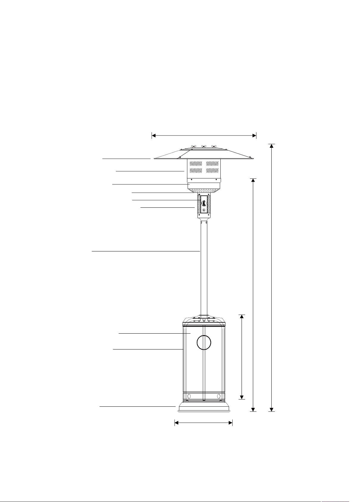
Variable control knob
Igniter
lgniter
CLEANING AND CARE
• Wipe off powder coated surfaces with soft, moist rag. Do not clean heater with cleaners
that are combustible or corrosive.
• Remove debris from the burner to keep it clean and safe for use.
• Cover the burner unit with the optional protective cover when the heater is not in use.
PARTS AND SPECIFICATIONS
- 5-
2222 mm
2003 mm
765 mm
813 mm
460 mm
Reflector
Flame screen
Burner base
Air admittance fence
Gas valve controller
Base of control housing
Post
Cylinder housing
Post bracket
Stand
LO
HI
Off
Igniter
Pilot
Stand with LPG cylinder housing
ASSEMBLY PARTS
Tools needed:
Open end wrench 10 & 13 mm
Adjustable opening wrench (2) 20 cm long
Slip joint pliers 23 cm long
Philips screwdriver w/ medium blade
Spray bottle of soap solution for leakage test
Parts supplied:
Assembly post with 3 pcs post brackets
Reflector 813 mm with 9 pcs Ø8 mm washers, 3 pcs M8 castle nut and
3 pcs M8 burner/reflector support bolt
4 pcs bolts M6 x 10 mm for assembly post and burner
6 pcs bolts & nuts M6 x 35 mm for post and post brackets
3 pcs bolts M8 x 16 mm for post brackets and stand
3 pcs ground fixer
6 pcs M6 x 10 mm ground fixer bolts & nuts
- 6 -

Place the cylinder housing on the stand.
ASSEMBLY PROCEDURES
STEP 1
1-1. Put the 3 pcs post brackets on each position on the base
as shown in the picture.
1-2. Use 3 pcs M8 x 16 mm bolts to join the post brackets and stand.
STEP 2
2-1. Put the post on the top of 3 pcs post brackets.
2-2. Use 6 pcs M6 x 35 mm bolts and nuts to connect the post to
the 3 pcs post brackets. Tighten the bolts and nuts.
STEP 3
- 7 -
Bolt
Post
STEP 2
Nut
STEP 3
Bolt
Stand
Post bracket
STEP 1
Cylinder housing

STEP 4
4-1. Fit the gas hose/pipe nut to the burner gas inlet connector.
4-2. Tighten the gas hose/pipe nut and gas inlet thread.
4-3. Fix the completed burner unit to the post by 4 pcs M6 x 10 mm bolts.
STEP 5
STEP 6-1
5-1. Check whether the connection of vertical post and burner are
assembled according to instructions, and all bolts and nuts
are tightened.
5-2. Put washer Ø8 mm on each reflector support bolt.
6-2. Fasten the reflector with 3 pcs washers and 3 pcs M8 mm dome nuts.
- 8 -
STEP 4
Bolt
STEP 5
STEP 6-2
Reflector
Wing nut
Reflector Spacer
4 SLICES ALU.REFLECTOR INSTALLATION
Warning: remove protective cover before assemble. 6-1

Bring up the cylinder housing and rest it on the post plate
Connect the regulator to the gas cylinder and tighten it with
adjustable wrench
Put LPG cylinder on the stand
Connect the end thread of inlet gas hose to the regulator
STEP 7
7-1.
7-2.
7-3.
7-4.
STEP 7
Regulator
Gas cylinder
9
Distributed by: D.K.Gas Appliances. PO Box 34191 Erasmia 0023
Name TOTAI
Model
Heat Output 13.0 KW
Gas Types
LPG
Injector Size Ø 1.90mm x 1
Operating
Pressure 2.8 kPa
Gas Consumption (at Max ) 940 g/h
PROBLEM
PROBABLE CAUSE
SOLUTION
Gas valve may be OFF
Turn the
gas valve ON
LPG cylinder empty Refill
LPG cylinder
Orifice blocked
Clean or replace Orifice
Air in supply system Purge air from lines
Pilot will not light
Loose connection
Check all fittings
Debris around pilot Clean dirty area
Loose connection
Tighten connection
.
Thermocouple bad
Replace Thermocouple
Gas leak in line Check connections
Pilot will not stay on
Lack of gas pressure LPG cylinder is near empty
Gas pressure is low LPG cylinder is near empty
Orifice blocked
Remove, clean and replace
Control knob not ON Turn knob to ON .
Thermocouple bad
Replace Thermocouple
Burner will not light
Pilot light assembly bent
or not in correct location .
Place pilot light in correct positi on
and retry
Repairs to the patio heater may only be carried out by a qualified technician
TAMPERING:
Under no circumstances are you allowed to tamper with the jet sizes or modify anything on
the appliance. Not only is it dangerous , it will also nullify your warranty
NOTE:
GAS-PRESSURE REGULATOR—This appliance is designed to operate on a gas pressure
of 2,8 kPa. A suitable bullnose regulator that complies with the requirements of SANS 1237
must be used with this appliance
Technical Specifications
Troubleshooting
FOR OUTDOOR USE ONLY
Specifications are subject to change without prior notice
16/DK1021A & 16/DK1022A
This manual suits for next models
1
Table of contents
Other Totai Patio Heater manuals


Popular Patio Heater manuals by other brands

Thermo
Thermo THI 2000 Safety instructions and operation manual

Lava Heat
Lava Heat SRPH30-XXXX ALTO owner's manual

Detroit Radiant Products
Detroit Radiant Products GPH Series user manual

AZ Patio Heaters
AZ Patio Heaters HPS-C-SS owner's manual

Superior Radiant
Superior Radiant HAB Series Manual for installation, operation & maintenance

Sunred
Sunred IND-3000H manual

SunGlo
SunGlo A270 Installation, operation and maintenance instructions

Jocel
Jocel JAT011893 instruction manual

GASLAND
GASLAND PHP40S installation instructions

Omcan
Omcan PH-CN-2210-S instruction manual

Blumfeldt
Blumfeldt Rising Sun Zenith manual

Napoleon
Napoleon PTH55PSS-1 User installation and operation guide


