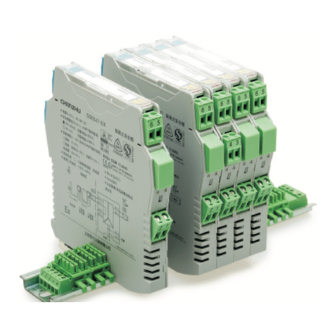
Number of channels: 2
Supply voltage: 20~35V DC
Current consumption: 80mA(at 24Vdc supply,20mA output)
Safe-area input:
Current: 0/4~20mA, HART digital signal
Voltage drop: ≤2V
Hazardous-area output:
Current: 0/4~20mA, HART digital signal
Load resistance: RL800Ω
Load resistance: RL≥250Ω(HART)
Voltage: 0/1~5V; Load resistance: RL≥330kΩ
Note: Users can specify current or voltage output when ordering.
each 90 of final value in 2ms
Power supply protection: Protect the barrier form reverse supply voltage
destroy.
Electromagnetic compatibility: According to IEC 61326-1(GB/T 18268),
IEC 61326-3-1
Dielectric strength:
Between non-intrinsically safe part and intrinsically safe part≥2500VAC
Between power supply part and non-intrinsically safe part≥500VAC
Insulation resistance:
Between non-intrinsically safe part and intrinsically safe part≥100MΩ
Between power supply part and non-intrinsically safe part≥100MΩ
Weight: Approx.135g
Suitable location: Mounting in non-hazardous area, and connected to
the IS apparatus in zone 0 hazardous area.
Suitable IS apparatus:
2-wire valve positioner, electric converter
≤
≤
Transfer accuracy: 0.1%F.S.
Temperature drift: 0.005%F.S./℃
Response time: R %
National Supervision and Inspection Center for Explosion Protection
and Safety of Instrumentation(NEPSI)
Compliancy with standard: IEC60079-0(EN60079-0)
IEC60079-11(EN60079-11)
IEC60079-26(EN60079-26)
GB12476.1 and GB12476.4
Ex-marking: [Ex ia Ga] ⅡC
[Ex iaD]
Maximum voltage: Um=250V
Intrinsic safety parameter: (9,10;12,13 terminals)
Uo=28V, Io=93mA, Po=651mW
ⅡC:Co=0.083μF , Lo=4.2mH
*ⅡB:Co=0.65μF , Lo=12.6mH
ⅡA:Co=2.15μF , Lo=33.6mH
Note: *ⅡB parameters also applicable for combustible dust atmospheres
[Ex iaD]
(1) For distributed inductance and capacitance e.g. as in a cable, allow
the values of capacitance and inductance;
(2) For circuits containing up to 1 % inductance or up to 1%
capacitance with a cable, allow the values of capacitance and inductance;
(3) For connection of the combined inductance and capacitance where
both are greater than 1% of the allowed value (excluding the cable), allow
up to 50% each of the values of capacitance and inductance.
Largest external capacitance (Co) and inductance (Lo) numerical
attention when using the following requirements:
118.9mm×106.0mm×17.5mm
1.These models have been assessed for using in IEC61508
functional safety applications.
2.Failure rates and safety-related parameters refer to the certificate.
Note: 1. It is not allowed to use HHC (HART hand-held communicator) in
hazardous area and safe area at the same time.
2.
must have an EX certification.
HHC (HART hand-held communicator) used in hazardous area
SIL 2
IEC 61508
1 2 3
Safe-area
Hazardous-area
Specification
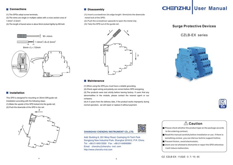
Operation side(HART) isolated barrier(2 channels), accepts
signal form safe area to drive valve positioners and other executive
mechanisms in hazardous area, also allows bi–directional transmission of
HART communication signals. The product needs an independent power
supply. Input circuit,output circuit and power supply are each galvanically
isolated.
4~20mA (1). The air should not contain any medium corrupting the coat of
chrome,nickel and silver.Moreover,violent quiver and impact or any cause
of electromagnetic induction (such as big current or spark,etc.)must be
avoided when using.
(2). Operating temperature: -20℃~+60℃
(3). Storage temperature: -40℃~+80℃
(4). Relative humidity: 10%~90%
Special requirements have to be confirmed before using the intrinsically
safe explosion loop system(intrinsically circuit) which connected by isolated
barrier and intrinsically safe apparatus in field:
(1) The explosion level of intrinsically safe apparatus should meet the
requirements of operation conditions. The apparatus should pass the
explosion protection test and get the certificate by state-authorized
explosion-proof product certification bodies.
(2) The intrinsic safety parameters of isolated barrier and intrinsically
safe apparatus both are sure, and comply with 12.2.5 of GB 3836.15-2000.
(3)If any parameters are unclear, the system has to be confirmed by
state-authorized explosion-proof product certification bodies.
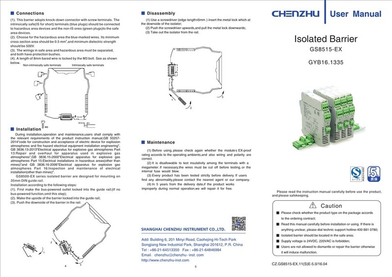
IN
9 (+)
2(-)
1(+)
7(-)
6(+)10(-)
12(+)
13(-)
4(-)
3(+)
OUT1
OUT2 IN2
IN1
HHC
HHC
I
P
I
P
HHC
HHC
-+
OUT
GS8568-EX
Valve position
Electrical converter
Power supply
Power supply
