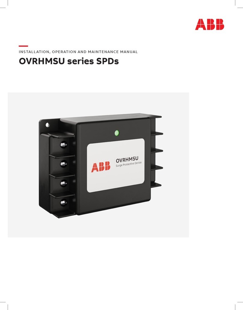
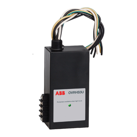
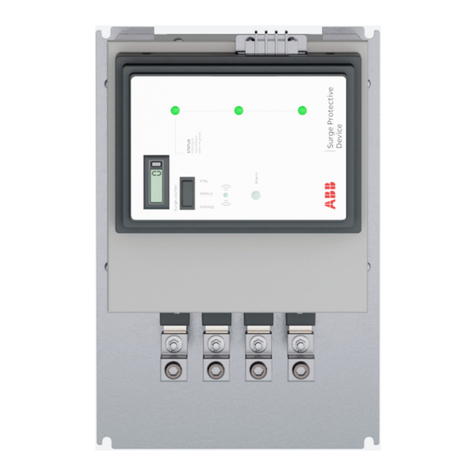
ABB OVRHT3D User manual

—
INSTALLATION, OPERATION AND MAINTENANCE MANUAL
OVRHT3D
Surge protective device (SPD)
• This manual shall be read in its entirety prior to installing.
• Failure to follow these instructions can result in death, serious injury
and/or equipment damage.
• SPD should be installed by a qualified electrician in accordance with
national and local electrical codes.
• Use appropriate safety precautions including personal protection
equipment.
• Cannot be used on ungrounded systems.
• The voltage rating of the SPD and system must be verified before
energizing the SPD.
• Hazardous voltages exist within SPDs when energized — SPDs should
never be installed or serviced when energized. During installation into
an electrical system, the SPD must not be energized until the electrical
system is completely installed, inspected and tested.
• Do not HIPOT the SPD unit or the electrical system in which the SPD
unit is connected without disconnecting the SPD unit’s conductors,
including phase, neutral and ground.
Installation
OVRHT3D units are Type 1 and do not require upstream overcurrent
protection for safe operation; however, the design may require or the
installer may choose to connect the OVRHT3D to a circuit breaker,
molded case switch or fused disconnect. If a breaker or molded case
switch is used for connecting the phase conductors, a 20–30 A breaker
is recommended. The unit must be installed in parallel to the electrical
distribution system. Careful consideration should be made in selecting
the knockout location. The SPD’s performance will be limited severely if
the conductors are A) too long, B) are of too small a wire gauge, C) have
too many bends or D) have sharp bends. Meet all national and local
codes. (NEC Article 242 addresses SPDs.) Do not splice SPD conductors
within the unit’s enclosure or manufacturer’s warranty will be void.
1. Prior to installation, ensure the system configuration and voltage
is equivalent to the SPD unit being installed.
2. Disconnect power to electrical panel. Use voltmeter to confirm
disconnection.
3. Remove the panel screws and cover. Retain these parts
for re-installation.
4. Remove appropriate sized knockout.
5. Mount SPD. Connect to equipment using an approved wiring method,
including seals appropriate for the enclosure rating.
6. Connect the white or blue wire to the neutral bar and tighten to
torque specified on inside of panel. Keep conductor length as short
as possible and avoid sharp bends.
7. Connect the green/yellow wire to the ground bar and tighten the
terminal to the torque specified inside of panel. Keep conductor
length as short as possible and avoid sharp bends. If neutral is bonded
to ground, green wire may be terminated to neutral.
8. Connect black or brown wires (model dependent) to the breaker or
the bus of the panel. Ensure the short circuit current rating does not
exceed 65, 100 or 200 kAIC. On High-Leg Delta units, connect the
orange wire to phase B (the high-leg). If the ability to turn off the unit
is desired, consider connecting it to a breaker (number of breaker pole
positions determined by the number of black or brown wires provided
with the unit). Tighten terminals to torque specified on inside of
panel. Keep lead lengths as short as possible and avoid sharp bends.
9. Re-install panel cover.
Operation
1. Apply power to the panel. If the phase, neutral and ground have been
wired correctly, the green function status LEDs will illuminate. If the
LEDs do not turn on, remove the power and review all of the previous
installation procedures.
2. If the LED light(s) does not illuminate and the SPD is tied to a breaker,
reset the breaker. If the LED light(s) illuminates after reset, the device
is ready for operation. If the LED does not illuminate after reset, or the
breaker will not reset, SPD must be replaced.
This unit contains no serviceable parts.
These instructions do no purport to cover all details for variations
in equipment nor to provide for every possible contingency.
Warranty
ABB warrants that Equipment (excluding Software) shall be delivered
free of defects in material and workmanship. The Warranty Remedy
Period for Equipment (excluding Software) shall end three (3) years after
the original date of purchase. If a nonconformity to the foregoing
warranty is discovered in the Equipment during the applicable Warranty
Remedy Period, as specified above, under normal and proper use and
provided the Equipment has been properly stored, installed, operated
and maintained and written notice of such nonconformity is provided to
ABB promptly after such discovery and within the applicable Warranty
Remedy Period, ABB shall, at its option, either (i) repair or replace the
nonconforming portion of the Equipment or (ii) refund the portion of
the price applicable to the nonconforming portion of Equipment. If any
portion of the Equipment so repaired or replaced fails to conform to
the foregoing warranty, and written notice of such nonconformity is
provided to ABB promptly after discovery and within the original
Warranty Remedy Period applicable to such Equipment or 30 days from
completion of such repair, replacement or re-performance, whichever
is later, ABB will repair or replace such nonconforming Equipment. The
original Warranty Remedy Period shall not otherwise be extended.
ABB shall not be responsible for providing temporary power, removal,
installation, reimbursement for labor costs or working access to the
nonconforming Equipment, including disassembly and reassembly of
non-ABB supplied equipment, or for providing transportation to or from
any repair facility, or for any other expenses incurred in connection with
the repair or replacement, all of which shall be at Purchaser's risk and
expense. ABB shall have no obligation hereunder with respect to any
Equipment which (i) has been improperly repaired or altered; (ii) has
been subjected to misuse, negligence or accident; (iii) has been used
in a manner contrary to ABB's instructions; (iv) is comprised of materials
provided by or a design specified by Purchaser; or (v) has failed as a
result of ordinary wear and tear. Equipment supplied by ABB but
manufactured by others is warranted only to the extent of the
manufacturer’s warranty, and only the remedies, if any, provided by
the manufacturer will be allowed. Software Warranty and Remedies.
ABB warrants that, except as specified below, the Software will, when
properly installed, execute in accordance with ABBʼs published
specification. If a nonconformity to the foregoing warranty is
discovered during the period ending one (1) year after the date of
shipment and written notice of such nonconformity is provided to
ABB promptly after such discovery and within that period, including a
description of the nonconformity and complete information about the
manner of its discovery, ABB shall correct the nonconformity by, at its
option, either (i) modifying or making available to the Purchaser
instructions for modifying the Software; or (ii) making available at ABBʼs
facility necessary corrected or replacement programs. ABB shall have no
obligation with respect to any nonconformities resulting from (i)
unauthorized modification of the Software or (ii) Purchaser-supplied
software or interfacing. ABB does not warrant that the functions
contained in the software will operate in combinations which may be
selected for use by the Purchaser, or that the software products are
free from errors in the nature of what is commonly categorized by
the computer industry as “bugs.”
Limitations and exclusions
THE FOREGOING WARRANTIES ARE EXCLUSIVE AND IN LIEU
OF ALL OTHER WARRANTIES OF QUALITY AND PERFORMANCE,
WHETHER WRITTEN, ORAL OR IMPLIED, AND ALL OTHER WARRANTIES
INCLUDING ANY IMPLIED WARRANTIES OF MERCHANTABILITY OR
FITNESS FOR A PARTICULAR PURPOSE OR USAGE OF TRADE ARE
HEREBY DISCLAIMED. THE REMEDIES STATED HEREIN CONSTITUTE
PURCHASER’S EXCLUSIVE REMEDIES AND ABB’S ENTIRE LIABILITY
FOR ANY BREACH OF WARRANTY.
WARNING Risk of shock, disconnect
power before installation.
Disconnect power before performing
any maintenance to device.
CAUTION
3
OVRHS3U401201P
OVRHS3U402401P
OVRHT3B(C)501201P
OVRHT3B(C)502401P
OVRHT3B(C)502771P
OVRHT3B(C)504801P
OVRHS3U401202S
OVRHT3B(C)501202S
OVRHT3B(C)502402S
OVRHS3U402083Y
OVRHS3U402773Y
OVRHS3U402303Y
OVRHT3B(C)501203Y
OVRHT3B(C)502203Y
OVRHT3B(C)502303Y
OVRHT3B(C)502403Y
OVRHT3B(C)502773Y
OVRHT3B(C)503473Y
OVRHT3B(C)502403H
OVRHS3U402403D
OVRHS3U404803D
OVRHT3B(C)502403D
OVRHT3B(C)503803D
OVRHT3B(C)504003D
OVRHT3B(C)504153D
OVRHT3B(C)504803D
OVRHT3B(C)506003D
Figure 4: 3-phase Delta, 3-wire
Figure 1: 1-phase, 2-wire Figure 2: 2-phase, 3-wire
Figure 3: 3-phase Wye, 4-wire
Figure 5: 3-phase High-Leg Delta, 4-wire
Note: high-leg orange must be
phase
A
3-pole
circuit breaker
A B
BC
C
N
N
G
N G
SPD
A
C
B
G
N
Earth
ground
Xo
bond
2-pole
circuit breaker
SPD
L1
L2
G
N
Earth
ground
Xo
bond
L1
N
L2
N G
L1
L2
N
G
1-pole
circuit breaker
SPD
G
N
Earth
ground
Xo
bond
L1
L1
N
N
G
N G
L
3-pole 1
circuit breaker
SPD
Earth
ground
Xo
bond
B
N
C A N G
N
G
A
B
C
G
N
A B C
3-pole
circuit breaker
B
C A N G
SPD
A
B
C
G
A B C
G
Earth
ground
4OVRHT3 SERIES AND OVRHS3U SERIESS U R G E P R OT E C T IVE D E V I C E S
CAUTION:
Do not assume the circuit is de-energized! Remove power before
performing any maintenance to these devices.
CAUTION:
Do not splice SPD conductors within the unit’s enclosure or
manufacturer’s warranty will be void. SPD’s performance will be
limited severely if the conductors are A) too long B) are of too small
a wire gauge C) have too many bends or D) have sharp bends.
CAUTION:
Prior to installation, confirm and ensure the system configuration
and voltage rating of the surge protector being installed.
OVRHT3B mounting
Connecting the remote contacts to an alarm
(If option chosen on the OVRHS3U)
For “fail-safe” Form “C” monitoring, use the labeled Form “C” wire
outputs to the alarm detection wires. Both outputs NO or NC
are available and either can be used dependent upon Negative or
positive logic choice. Relay contacts are rated for 1A, at 150Vac or
60Vdc maximum.
Relay contacts shown in the relaxed position
(protector alarm or loss of power).
Note: Maximum torque on terminals is 10 in-lbs.
RE
M
OT
E
AL
AR
M
1
2
3
1
2
3
Protector
Service Panel Side
N
G
Electrical Service Entry
Surge
Protector
Service
Panel Side
MountingSurface
Ground
N
G
L
Optional
Circuit
Breaker
Neutral
bars
Optional
circuit breaker
N
G
Surge protector
Line wire
OVRHT3C mounting
OVRHS3U mounting
Additional information
We reserve the right to make technical
changes to the product and to the
information in this document without
notice. The agreed conditions at the time
of the order shall apply. ABB assumes no
responsibility for any errors or omissions
that may appear in this document. We
reserve all rights in this document and in
the information contained therein.
Without prior written approval from ABB,
reproduction, disclosure to third parties
or use of any information, in whole or in
part, is strictly forbidden.
—
Electrification Products
5900 Eastport Boulevard
Richmond, VA 23231-4453 USA
Tel: +1 800 292 3739
Fax: +1 804 236 4047
abb.com
© Copyright 2017 Thomas and Betts Power Solutions, LLC. All rights reserved.
Specifications subject to change without notice.
PN: 750-0122-008 A00090617
Locknut
750-0198-001-10.2022
—
We reserve the right to make technical
changes or modify the contents of this
document without prior notice. With regard
to purchase orders, the agreed particulars
shall prevail. ABB Inc. does not accept any
responsibility whatsoever for potential
errors or possible lack of information in
this document.
We reserve all rights in this document
and in the subject matter and illustrations
contained therein. Any reproduction or
utilization of its contents – in whole or in
parts – is forbidden without prior written
consent of ABB Inc. Copyright© 2022 ABB.
All rights reserved.
—
USA
ABB Inc.
305 Gregson Drive
Cary, NC 27511
(888) 385-1221
electrification.us.abb.com/
products/surge-protective-devices
3
OVRHS3U401201P
OVRHS3U402401P
OVRHT3B(C)501201P
OVRHT3B(C)502401P
OVRHT3B(C)502771P
OVRHT3B(C)504801P
OVRHS3U401202S
OVRHT3B(C)501202S
OVRHT3B(C)502402S
OVRHS3U402083Y
OVRHS3U402773Y
OVRHS3U402303Y
OVRHT3B(C)501203Y
OVRHT3B(C)502203Y
OVRHT3B(C)502303Y
OVRHT3B(C)502403Y
OVRHT3B(C)502773Y
OVRHT3B(C)503473Y
OVRHT3B(C)502403H
OVRHS3U402403D
OVRHS3U404803D
OVRHT3B(C)502403D
OVRHT3B(C)503803D
OVRHT3B(C)504003D
OVRHT3B(C)504153D
OVRHT3B(C)504803D
OVRHT3B(C)506003D
Figure 4: 3-phase Delta, 3-wire
Figure 1: 1-phase, 2-wire Figure 2: 2-phase, 3-wire
Figure 3: 3-phase Wye, 4-wire
Figure 5: 3-phase High-Leg Delta, 4-wire
Note: high-leg orange must be
phase
A
3-pole
circuit breaker
A B
BC
C
N
N
G
N G
SPD
A
C
B
G
N
Earth
ground
Xo
bond
2-pole
circuit breaker
SPD
L1
L2
G
N
Earth
ground
Xo
bond
L1
N
L2
N G
L1
L2
N
G
1-pole
circuit breaker
SPD
G
N
Earth
ground
Xo
bond
L1
L1
N
N
G
N G
L
3-pole 1
circuit breaker
SPD
Earth
ground
Xo
bond
B
N
C A N G
N
G
A
B
C
G
N
A B C
3-pole
circuit breaker
B
C A N G
SPD
A
B
C
G
A B C
G
Earth
ground
—
Figure 1: 1-phase, 2-wire
OVRHT3D501201P
OVRHT3D502401P
OVRHT3D502771P
OVRHT3D504801P
—
Figure 2: 2-phase, 3-wire
OVRHT3D501202S
OVRHT3D502402S
—
Figure 3: 3-phase Wye, 4-wire
OVRHT3D501203Y
OVRHT3D502203Y
OVRHT3D502303Y
OVRHT3D502403Y
OVRHT3D502773Y
OVRHT3D503473Y
—
Figure 4: 3-phase Delta, 3-wire
OVRHT3D502403D
OVRHT3D503803D
OVRHT3D504003D
OVRHT3D504153D
OVRHT3D504803D
OVRHT3D506003D
—
Figure 5: 3-phase High-Leg Delta, 4-wire
OVRHT3D502403H
—
OVRHT3D mounting
Electrical connections
Other ABB Surge Protector manuals
Popular Surge Protector manuals by other brands

Rocket Fish
Rocket Fish RF-PCS12ES13 Guía De Instalación Rápida

RVsecure
RVsecure Protector Zero Installation and operating manual

Radio Shack
Radio Shack 61-2425 owner's manual

Belkin
Belkin Conserve Switch user manual

Superior Electric
Superior Electric STABILINE DIN3-165 Series owner's manual

SC&T
SC&T SP008 user manual