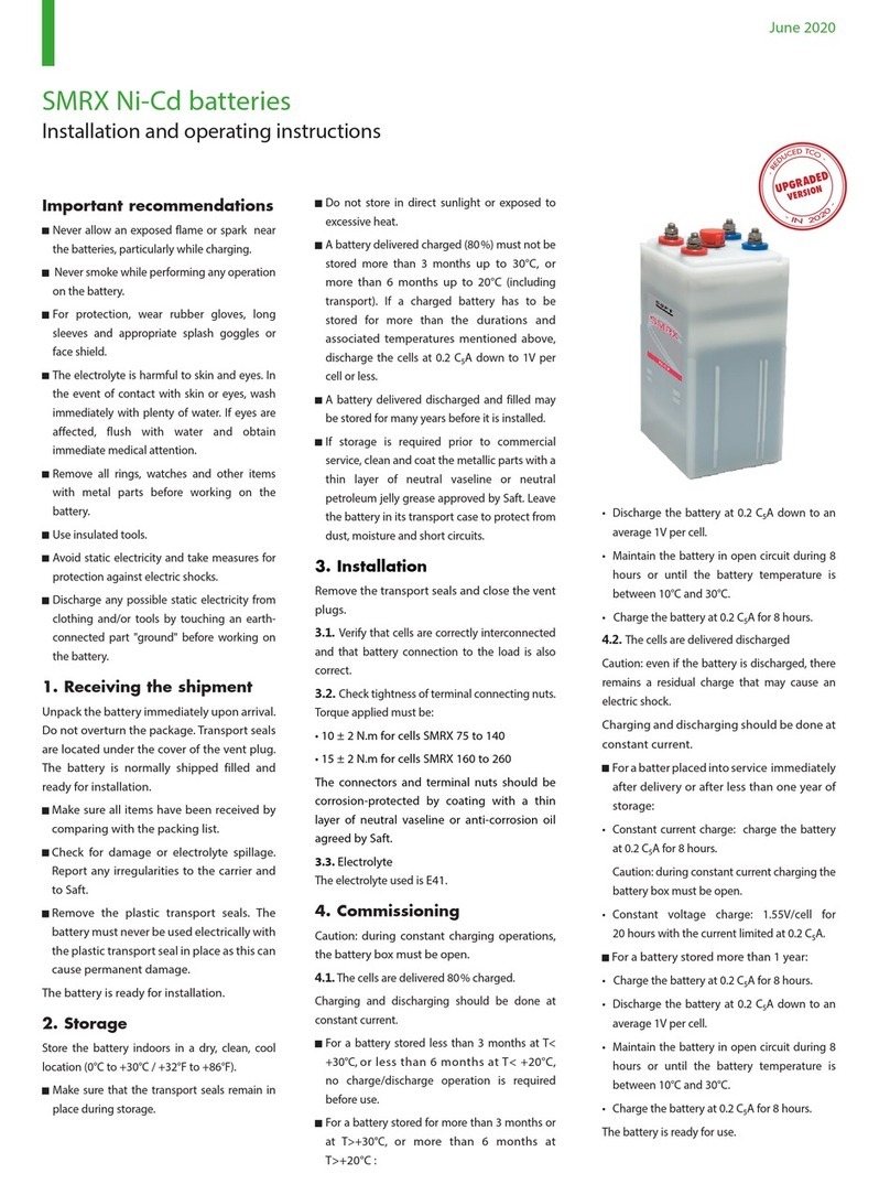
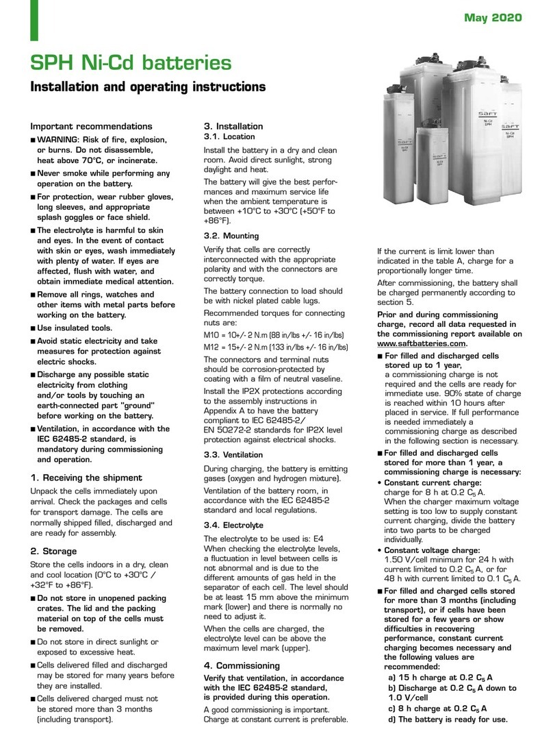
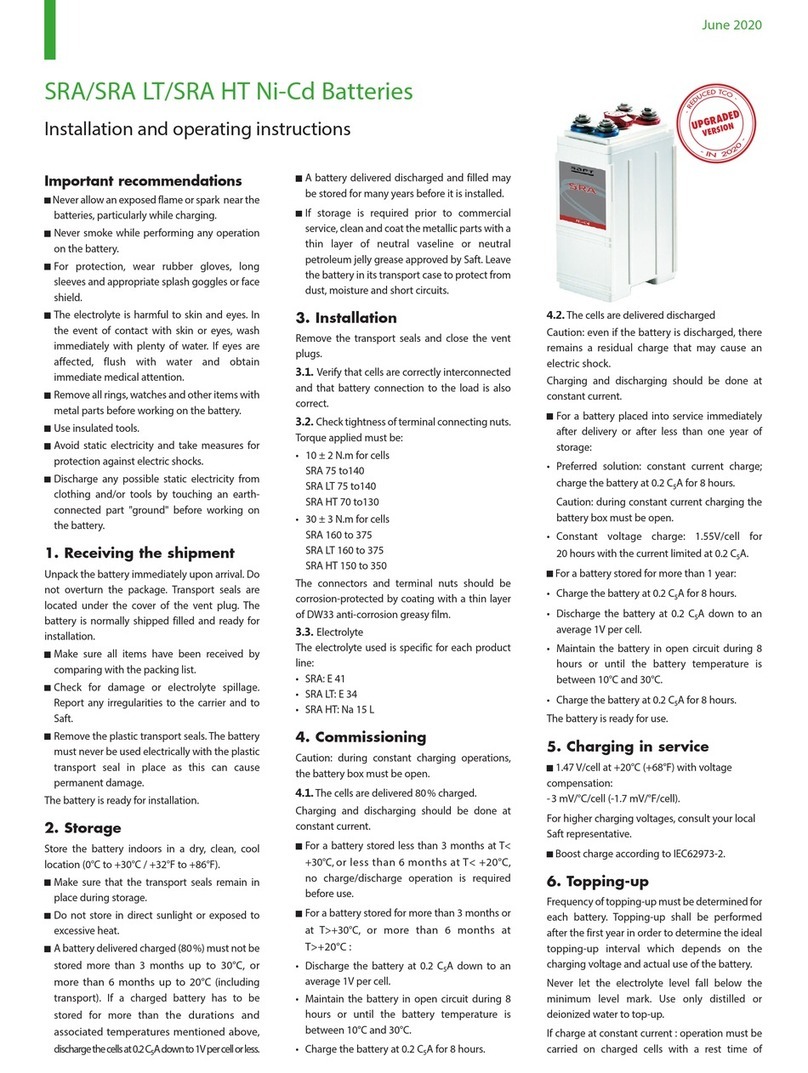
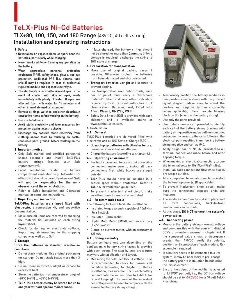
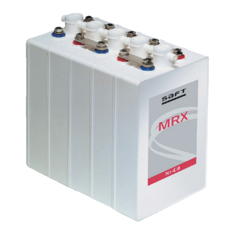
Total SAFT Flex'ion Series User manual

Flex’ion®
Transportation, Storage, Installation and Operation Instructions
October 2019
1. Introduction
Flex’ion® is a family of Li-ion battery
systems that includes large format
Li-ion cells and the necessary
electronics for providing power
backup for mission critical
applications.
This quick start guide describes how
to transport, store, install and
operate the battery system. Within
this document, the necessary tasks
are noted with
Fx#
and they are
arranged in the order that they
should be executed.
Please consult the Flex’ion
Installation & Commissioning and
Operation & Maintenance Manuals
for full instructions.
2. Safety
A battery system is an active electrical
device that contains a specific quantity
of energy. The Safety Rules below
must be complied with to ensure
correct handling and operation.
Saft products are designed with
safety considerations; however,
batteries can be dangerous if used
incorrectly.
Failing to comply with the Safety
Rules described below may cause
the battery system to fail and may
cause serious injury.
Improper operation of the product
may cause a cell to overheat or
vent.
Safety Rules:
Read these instructions fully before
installing and operating the battery
system.
Batteries MUST be installed in a
restricted access area only. Only
authorized personnel Trained and
Certified according to the local rules
(for example per NFPA 70E in U.S.)
to handle High Voltage Hazard
should be allowed to enter the
restricted area and work on the
system.
Batteries must be installed in a
location that can be easily ventilated
in case of misuse, such as
described below.
Never short-circuit the battery
terminals.
Do not reverse the polarity.
Do not overcharge or over-discharge
the battery.
Adhere to factory voltage range
specification given in this document.
Do not open the battery module.
Do not disassemble the unit.
Do not use the battery without its
electronic management system.
Do not subject to excessive
mechanical stress.
Do not expose the unit to water or
condensation.
Install the batteries in an area
compatible with pollution level 2
according to EN 60664-1 (typical of
office or laboratory environments).
Do not place the batteries on or
near fires or other high-temperature
locations (> 70°C). Doing so may
cause the batteries to overheat or
vent. Using the batteries in this
manner may also result in the loss
of performance and reduce product
life expectancy.
Immediately disconnect the batteries
if, during operation, they emit an
unusual smell, feel hot, change
shape, or appear abnormal in any
other way. Contact Saft immediately
if any of these problems are
observed.
Connect to power systems/rectifiers
with maximum rated output of Vmax
only (refer to Table 1).
Refer to the Battery Information
Sheet (BIS) for emergency response
procedures and personal protective
equipment in case of an abnormal
event.
If smoke is emitted from the system,
stay clear of the smoke and
evacuate the area immediately.
For normal handling and operation
according to this installation and
operation document, personal
protective equipment (PPE) is
required.
3. Tools
The necessary installation tools are
described in Table 2. These tools are
not provided with the battery system.
4. Receiving, Unpacking and
Inspection
Flex’ion components are packaged in
accordance with UN3480 Class 9A.
Fx1 Check that all items
are received against
the packing list.
Table
3
If items were not received or if
anything was damaged, do not install
the component. Please contact your
local Saft representative.
Fx2 Study Flex’ion®
features
Figure
3,4,5
The Flex’ion® battery system
comprises one or more STRINGs
(depending on the configuration),
managed by a single Master Battery
Management Module (MBMM, refer to
Figure 3). One STRING comprises:
Electrical cabinet
Battery Management Module (BMM)
A minimum of three battery modules
connected in series (depending on
the configuration)
An Intelli-Connect™ module with
MBMM + PLC device
Communications and power cables
Documentation set
Fx3 Check the condition
before and during
storage and prior to
installation.
Table
4
Always keep the Flex’ion components
together in their original packaging.

5. Storage
Store the battery system components
in their original packaging under these
conditions to optimize product lifetime:
Recommended range +20°C (68°F)
to +40°C (104°F)
No direct sunlight, rain or flooding
(IP20).
≤ 95% relative humidity (RH)
maximum. (non-condensing).
The BMM circuit breaker set to
“OFF” position (open circuit).
Modules are shipped at these SOC:
1. Road and sea freight: 50% SOC
2. Air freight: 30% SOC
Due to self-discharge, the battery
modules must be recharged as
follows:
1. Road and sea freight shipment –
not later than 250 days from
dispatch day from Saft
2. Air freight shipment – not later
than 130 days from dispatch day
from Saft (second recharge must
follow not later than 250 days
under condition that the previous
recharge was to 50% SOC)
Saft recommends recharging to
50% SOC.
For individual module charging,
please contact Saft.
The aforementioned durations are
valid when maximum storage
temperature is 25°C (ideal storage
temperature 10°C).
Fx4 After 6 months, check
the SOC once per
month in storage.
Figure
6
NOTE:
Acceptable storage temperature range
is from -20°C to +50°C (-4°F to
122°F). Depending on this range, a
refreshing charge may be required
more frequently.
6. Transportation and packing
Flex’ion systems are transported
disassembled. The cabinet, BMM and
battery modules have their own
packaging for transportation.
The Li-ion battery modules are shipped
from Saft in packaging compliant with
UN Requirements for the Transport of
Dangerous Goods (UN 3480) and
applicable regulations such as IATA
(Air), IMDG Code (Maritime), ADR
(Road in Europe) and any other local
regulations required.
The battery module package must
display a class 9A hazard label in
addition to markings identifying the
applicable proper shipping name
(Lithium-ion batteries) and UN number
(3480).
When packing, avoid any risk of short-
circuits between the terminals.
Ensure all packaged components are
protected from damage during
transportation.
Transport and storage of defective
batteries
If the Li-ion battery module is identified
as being damaged or defective (has
leaked, sustained physical or
mechanical damage or is defective for
a safety reason) it shall be packed in
accordance with packing instructions
P908 or LP904 of IMDG Code
(Maritime) / ADR (Road in Europe)
regulations as applicable. According to
IATA (Air) regulations, the lithium
batteries identified by the
manufacturer as being defective for
safety reasons, or that have been
damaged, and have the potential of
producing a dangerous evolution of
heat, fire or short circuit are forbidden
for air transportation (e.g. those being
returned to the manufacturer for
safety reasons).
Packaging used shall conform to the
packing group II performance level.
Each (potentially) damaged or
defective battery module shall be
individually packed in an inner
packaging. The purpose of the inner
packaging (e.g. plastic bag) is to
collect any potentially released
electrolyte.
Each (potentially) damaged or
defective battery module in the inner
packaging must be put into an
interlayer. The interlayer comprises
a sufficient amount of absorbing,
non-combustible and electrically non-
conductive thermal insulation
material (e.g. vermiculite in an
aluminum bag) to absorb any
possible leak from the inner
packaging and to protect against
dangerous evolution of heat.
Each (potentially) damaged or
defective battery module in the inner
packaging and interlayer must be
put into an outer packaging. The
outer packaging (box, drum) protects
against any further damage and/or
dangerous condition during carriage.
Appropriate measures shall be taken
to minimize the effects of vibration
and shock and prevent movement
within the package. Cushioning
material that is non-combustible and
electrically non-conductive may also
be used.
Packages must be additionally marked
“DAMAGED/ DEFECTIVE LITHIUM-ION
BATTERIES”.
Saft must be contacted when safety is
a concern or in case of any doubt, to
determine how to proceed in such
instances and the appropriate shipping
method.
Flex’ion®
Figure 2: Package marked as damaged/
defective lithium-ion batteries
Figure 1: Packaging of (potentially)
damaged or defective battery module

7. Installation
Before installing, double check the
condition of each battery module.
Fx5 Size the correct
number of battery
modules to connect to
the DC bus.
Figure
3,4,5
Before installing, ensure the right
number of battery modules are
connected in series to support the DC
bus.
Fx6 Check for maximum of
2V difference between
battery modules
operating on the
same DC bus.
Figure
7
If battery modules have more than
2.0Vdc difference, then recharging is
necessary. Consult Saft for full
instructions.
Fx7 Connect the battery
modules.
Figure
7,8,9
Before system integration, verify that
all the components inside the cabinet
are correctly attached to the rack and
connected with relevant tightening
couples.
Full system installation and
commissioning may only be performed
by an engineer certified by Saft. This is
required to activate the system
warranty:
Connect power cables between
BMM and Intelli-Connect.
The power connections of the BMM
with the first and last battery modules
of each string are performed though
the HV terminals “VIN-BAT” and
“VIN+BAT” located on the BMM front
face (refer to Figure 6).
The power connections of each
battery string, once assembled, are
performed through the HV terminals
“VOUT-DC” and “VOUT+DC” located
on the BMM front face (refer to
Figure 6).
Connect Low Voltage cable (installed
in Cabinet) to BMM.
Connect CAN bus cable between
battery modules and BMM.
If the battery system comprises
multiple parallel strings, connect
BMM #01 communication port to
BMM#02, etc. (refer to Figure 6).
Connect the MBMM signals to the
customer’s application (when
requested).
Connect the electrical power cables
between battery modules, BMM and
Intelli-Connect using insulated tools.
Connect the battery string to the dc
bus of the application. The power
connections of each battery module
are performed via the high voltage
(HV) “+” and “- “terminals located on
the front face. Personal protective
equipment is required.
Fx8 Power ON Figure
9
Reclose/reengage the circuit
breaker on each BMM.
According to the configuration,
press the push ON/START button
on the front door of the master
cabinet (refer to Table 4).
Flex’ion®
IMPORTANT:
Never leave the Flex’ion® ON when it is
not in use. The internal electronics will
self-discharge the cells to a low voltage
alarm level which may render the
module un-usable.
8. Operation/Maintenance
Flex’ion provides uninterrupted standby
power anytime the AC power supply is
OFF. Continue trouble-free operation by
complying with these instructions.
Battery modules do not require regular
maintenance. Periodically checking the
complete Flex’ion system during other
site routines is recommended (more
details are available in the Operating &
Maintenance manual).
LED state (refer to Table 4).
Clean any excessive dirt build-up
using a nonmetallic brush or a dry
or damp cloth.
Do not use any cleaning solvents or
soaps.
Do not immerse, bathe or hose off
the Flex’ion system.
Charge and discharge of the Li-ion
battery must be monitored and
managed with respect to parameters
such as current, cell voltages and
module temperatures. This
management is performed by the
battery module at the cell level and
BMM at string level.

Table 3: Battery string comprising 11 modules*
Item Module Description Qty
A EC Electrical cabinet 1
B BMM Battery Management Abbreviation 1
C ##P/MFe Battery modules 11
D I-C Intelli-Connect™ with Master BMM 1
E CAB Signal and power cables 1
F DOC Documentation set 1
* actual configuration is subject to design parameters
Figure 3: Configuration example of two cabinets in
parallel, each comprising 11 modules in series to
provide nominal 508 Vdc and 268 kW for 5 minutes.
Flex’ion®

Flex’ion®
Figure 4: System overview of standard, 2-wire architecture
of multi-string system
Figure 5: System overview of midpoint, 3-wire architecture of
multi-string system

Flex’ion®
WARNING:
Always use insulated tools while working with Flex’ion®
components and battery modules.
NOTE:
Always use personal safety equipment while working with
Flex’ion® components and battery modules.
Figure 6: Power and Signal connectors
Figure 7: Check the maximum voltage of modules
Figure 8: BMM overview
Figure 9: POWER ON main switch
IMPORTANT:
Full instructions are provided in the Flex’ion Installation &
Commissioning (available to installation engineers certified
by Saft) and Operating and Maintenance Manuals (available
upon request).
NOTE:
Always use trained personnel when working with Flex’ion
systems, components and battery modules.
Battery Module, 46 Vdc
Battery Module, 23 Vdc
Battery Management Module (BMM)
Intelli-Connect™ and
Master BMM + PLC


Saft Ferak
Industrial Standby Division
Raskovice 247
739 04 Prazmo
Czech Republic
Tel: +420 558 426 268
Saft America Inc
Industrial Standby Division
3 Powdered Metal Drive
North Haven, Connecticut, 06492
United States of America
Tel: +1 203 985 2700
Fax: +1 203 985 2739
www.saftbatteries.com
Doc. Nº 22026-1019-2
Edition: October 2019
Data in this document is subject to change without
notice and becomes contractual only after written
confirmation.
Société Anonyme au capital de 26 300 205
€
RCS Nanterre 481 480 46
Le Révérend Imprimeur - Printed in France
This manual suits for next models
3
Table of contents
Other Total Camera Accessories manuals