1
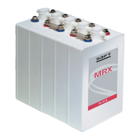
Tel.X-Plus Ni-Cd Batteries
TLX+80, 100, 150, and 180 Range
(48VDC, 40 cells string)
Installation and operating instructions
1Safety
•
Never allow an exposed flame or spark near the
batteries, particularly while charging.
•
Never smoke while performing any operation on
the battery.
•
Wear appropriate personal protection
equipment (PPE), safety shoes, gloves, and eye
protection. Additional PPE (i.e. aprons, face
shield) may be required in case of accidental
ruptured module and exposed electrolyte.
•
The electrolyte is harmful to skin and eyes. In the
event of contact with skin or eyes, wash
immediately with plenty of water. If eyes are
affected, flush with water for 15 minutes and
obtain immediate medical attention.
•
Remove all rings, watches, and other electrically
conductive items before working on the battery.
•
Use insulated tools.
•
Avoid static electricity and take measures for
protection against electric shocks.
•
Discharge any possible static electricity from
clothing and/or tools by touching an earth-
connected part "ground" before working on the
battery.
2Important notice
•
Only Saft trained and certified personnel
should assemble and install Tel.X-Plus
battery strings (contact your Saft
representative).
•
Local regulations related to battery
compartment ventilation (e.g. Telcordia GR-
487-CORE) should be carefully observed. Saft
will not be responsible for the non-
observance of these regulations.
•
Refer to Saft's Installation and Operation
manual for complete instructions.
3Unpacking and inspection
Tel.X-Plus batteries are shipped filled with
electrolyte, a connection kit, and supportive
documentation.
•
Make sure all items are received by checking
the material list included on each string
layout sheet.
•
Check for damage or electrolyte spillage.
Report any abnormalities to the shipping
company as well as to Saft.
4Storage
Store the batteries in standard warehouse
conditions.
•
Do not stack modules. Use original packaging
for storage. Do not stack boxes more than 3
high.
•
Do not store in direct sunlight or expose to
excessive heat.
•
Store the batteries in a temperature range of
-20°C (-4°F) to +35°C (+95°F).
•
Tel.X-Plus batteries may be stored for up to
one year without special maintenance.
•
If fully charged, the battery strings should
not be stored for more than 2 months (if long
storage is required, discharge the string to
10% state of charge).
5Preparation for transportation
•
Make use of original packing cases if
possible. Otherwise, protect the batteries
from being damaged and short-circuited.
•
Transport batteries upright and secured to
prevent tipping.
•
For transportation over public roads, each
box or pallet must carry a "hazardous
material" label and any other indication
required by local transport authorities (DOT
classification; Batteries, Wet, Filled with
Alkali, Class 8, UN2795, PG III).
•
Safety Data Sheet (SDS) is provided with each
shipment and is available online at
www.saftbatteries.com.
6Installation
6.1 General
Tel.X-Plus batteries are delivered filled with
electrolyte and at 10% State of Charge (SOC).
•
Do not top up batteries with DI water before,
during, or after initial installation.
•
Charge the battery (according to chapter 6.6).
6.2 Operating environment
•
For tight spaces and to use a front accessible
connection, make sure to install all back
connections first, while blocks are staged
outside.
•
Tel.X-Plus should never be installed in a
sealed space without ventilation. Refer to
Table A for ventilation guidelines.
•
To prevent inadvertent short circuit, make
sure the connector
ends are insulated.
6.3 Recommended tools
The following tools will facilitate installation:
•
Insulated torque wrench capable of 10±1N.m
(96 ± 9in.lbs).
•
Insulated 10mm socket
•
Digital Multi Meter (DMM), with an accuracy
of +/-10mVDC.
•
Clamp-on current meter, with an accuracy of
±25mA.
6.4 String assembly
Battery configurations vary depending on the
application. A battery string layout is provided
with each string. The step by step procedures
may vary with application and layout.
•
Measuring the cell Open Circuit Voltage (OCV)
is recommended to check for normal cell
condition (according to chapter 8). Before
installation, measure the OCV of each battery
cell and note the values (refer to Table B for
record keeping). The sum of the individual
cell voltages will be used to compare with the
assembled battery string voltage.
•
Temporarily position the battery modules in
final position in accordance with the provided
layout diagram. Make sure to orient the
positive and negative terminals correctly
(when applicable, place barcode bearing
block on the (+) end of the battery string).
•
Use only the parts provided.
•
Use “labels numerical” provided to identify
each cell of the battery string. Starting with
battery string positive end as cell number one,
subsequently serialize the cells following the
electrical path resulting in numbering battery
string negative end cell as #40.
•
Apply a light coat of No-Ox (provided) to all
terminal connections made before and after
applying torque.
•
When making an electrical connection, torque
the terminal bolts to 10±1N.m (96±9in.lbs).
•
Install all back connections first while blocks
are staged outside.
•
After completing terminal connections, install
the battery top cover(s) (If applicable).
•
To prevent inadvertent short circuit, make
sure the connectors’ exposed ends are
insulated.
•
The modules can then be slid into place and
all front connections, back-to-front
connections can be made.
•
At this stage, DO NOT connect the system’s
power cables.
6.5 Connecting power
•Measure the battery string’s overall voltage
and compare this with the sum of individual
OCV’s previously measured in chapter 6.4. If
the compared value shows a discrepancy
greater than 1.0VDC, verify the polarity,
position, and connection of each module. Re-
assemble if required.
•
If a battery needs to be connected to a live
system, it may be necessary to pre-charge
the battery prior to installation (to minimize
the inrush current).
•Ensure the output of the rectifier is adjusted
to 1.43VDC per cell; i.e., the DC bus voltage
should be set to -57.2VDC for a 40 cell Tel.X-
Plus string.


