TouchTronics PowerTouch 914 User manual

NST13308-P914_A 2020-06-10 Page 1
57315 Nagy Dr
Elkhart, IN 46517
800-294-2570
574-294-2570
www.touchtronics.com
By TouchTronics, Inc.
Power
All four outputs are 5 amp, switched relays.
Flexibility
Installer can select polarity of voltage outputs on all channels.
Optional Transmitters
Large, oval transmitters with large buttons can be ordered.
Standard 4 Channels
Two and four channel transmitters are interchangeable.
Special Features and Applications
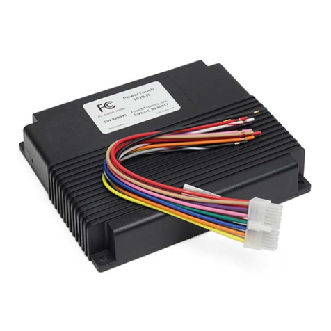
914 PowerTouch Remote Control Receiver
With Two (4 button) Key Chain Transmitters
Also showing optional:
Two (two button) Key Chain Transmitters
And Oval Transmitter
co mi l
Eno ca
nd
a
Ver t esa il
Please read entire instruction manual prior to starting the
PowerTouch Remote Contr ol System Installation.
PowerTouch 914
Range
Typical antenna range is 60-feet.
Compact
Receiver is small and easy to install.
Pr ogram Options
Two channels can be programmed as latching,
On - Of
f
Channel 2 can be programmed with a 2-second courtesy light delay

NST13308-P914_A 2020-06-10 Page 2
Contents
Special Features and Applications Page 1
Contents, Specications, InstallationTools, Technical Support Page 2
Component Parts List Page 3
Operation: Remote Control Page 3
Installation: Planning Page 4
Installation: Receiver Page 4
Installation: Electrical Connections Page 5
Installation: Application Schematics Page 6
Installation: Motors Using Relays, Safety Disable Switch Page 7
Trouble Shooting Guide Page 8, 9, 10
Limited One (1) Year Warranty Page 11
Blank Page (Installation Notes or Diagrams) Page 12
Specications
914 Receiver: FCC Approved
RF System 19,000 Digital Codes
Voltage 12 Volt DC (available in 24 Volt DC)
Output 5 Amp
Frequency 300 MHz
Range 60 Feet (typical - using standard 9” wire style, antenna)
Note: Range may be extended with an externally mounted antenna
914 Transmitter: FCC Approved
RF System 19,000 Digital Codes
Battery 12 Volt DC
Cycles 7,300 One Second Pulses
Frequency 300 MHz
Note: Key chain style transmitters are water resistant, NOTwater proof
Oval style transmitters are water and dust resistant
Physical:
Receiver: 4.5” x 2.5” x 1” (width, height, depth)
Transmitter: 1” x 2” (width, length) key chain style
2” x 4 ½” (width, length) oval(hand held) style
Installation Tools
Voltmeter, analog or digital
Phillips Screw Driver
Adjustable Wrench
Screw Driver
Wire Cutter
Wire Stripper
To Clean Grounding Pad: Scraper, Sand Paper, Alcohol Based Cleaner
Technical Support
Visit the factory website to download a copy of these instructions, e-mail technical questions and see other
TouchTronics, Inc. products.
Phone / Fax Numbers
Indiana Local 1-574-294-2570
Toll Free 1-800-294-2570
Fax 1-574-293-1611
Web Site
www.touchtronics.com
E-Mail
‘Contact Request’link on the web page

X
NST13308-P914_A 2020-06-10 Page 3
1) 1 pc 914rRF Receiver , 4 Channel
w/9” antenna wire
2) 1 set 914hHarness - 10 wire, 9”
3) 2 pcs 914T4 Transmitter,
4 button key chain style
Optional 914T2 Transmitter,
2 button key chain style
Optional 914T4XS Transmitter,
4 button oval (hand held) style
Component Parts List
Operation: Remote Control
Transmitters:
1) Press and releasebutton
Or
2) Press and hold button
3) Red Status LED
Signal is sent to receiver - 1 second pulse
Signal is sent to receiver as long as button
is held. Signal will stop when button is
released.
A) LED On red indicates signal is being
sent
B) LED On bright and solid indicates
battery voltage is ok.
2 Button
1
1 & 2
2
N/a
Channel
1
2
3
4
Function
Motor or Lamp
Motor or Lamp
Motor or Lamp
Motor or Lamp
Power Output
+12v or Ground(-)
+12v or Ground(-)
+12v or Ground (-)
+12v or Ground (-)
Signal T ype
Momentary
Momentary
22 sec delay (ch 4)
Momentary
Or Latching
Momentary
Or Latching
Transmitter Operation Receiver Operation
Output
5 Amps Max
5 Amps Max
5 Amps Max
5 Amps Max
*Example - Courtesy light turns on for 22 seconds when button 2 is pressed,
and the channel 4 output is connected to the courtesy lights.
All outputs must be same polarity
*See example below
4 Button
1
2
3
4
Transmitter Transmitter
Pr essed at the
same time

NST13308-P914_A 2020-06-10 Page 4
1) Receiver Output Voltages
A) The receiver has four output voltage (channels) which will operate four separate circuits. The
output voltage is 12 volts direct current (vdc).The maximum drive current for each of the four
output channels is 5 Amps (maximum) . The four outputs can turn On (drive) bulbs, relay coils or
small motors.
B) Check the power requirement for the bulb or motor before connecting to the receiver.
Maximum 5 amps @ 12vdc or 60 watts @ 12vdc
2) Determine where the receiver and antenna will be located.
Typically the RF receiver is located under the dash or behind a wall panel in the back. If the receiver
is to be mounted outside the cab area then you must protect the receiver. The receiver is NOT
waterproof or moisture resistant*.
DO NOT mount the receiver and antenna:
A) Within 6 feet of a motor
B) Near lar ge bundles of wires
C) Near other antennas or RF devices
D) The antenna should not be touching any metal as this grounds the RF (radio
frequency) signal
*T ouchTronics offers weather resistant housings for many different types of applications. Call the
factory @ 1-800-294-2570 for information on yourparticular application needs.
Installation: Planning
Installation: Receiver
(-)
Battery
(+)
12
11
10
09
08
07
06
05
04
03
02
01
PowerT ouch Remote Contr ol System
Series 914 RF Receiver
This device complies with FCC rules part 15.
Operation is subject to the following 2 conditions:
1) This device may not cause harmful interference
2) This device must accept any interference received
including that causing undesired operation
9” Antenna Wire
*Maximum output current 5 Amps. Overcurr ent will damage outputs.
1a Maximum
12
11
10
09
08
07
06
05
04
03
02
01
White/Tan
Purple
Tan
Green/Black
Yellow/Black
Green/Red
Yellow/Red
Empty
Orange
Black
Empty
Red
Ch 4 - Output, 5 amp
Power +12v - 5 amp
Ch 3 - Output, 5 amp
Ch 1 - Input for rr@g circuit (-)*
Ch 2 - Input for rr@g circuit (-)*
Ch 1 - Output, +12v, 5 amp
Ch 2 - Output, +12v, 5 amp
Empty
Do Not Use
Chassis Ground
Empty
Logic +12v
*RR@G - Reversal Rest @ Gr ound
Notes:
1) Channels 1 and 2 are momentary outputs as long as the button is pressed.
2) Channels 3 and 4 are factory set as momentary outputs as long as the button is pressed. These outputs can be
programmed as latching (push on - push off). Call the factory for program information at 1-800-294-2570
10a Maximum
Range of your Remote
Control is affected by
the installation location
of the receiver antenna
Warning!
Use only a voltmeter to check voltage during installation and testing.
*Using a test light WILL damage the outputs!
*See Note Below
Scrape paint and clean area before installing ground screw
#10 x 3/4” Screw
#10 3/16” Star Washer
#10 3/16” Ring Terminal
Vehicle Frame
CHASSIS GROUND

NST13308-P914_A 2020-06-10 Page 5
1) Install Power
Connect the Red wire to a constant +12v battery power source. Note: For best performance, run a
clean +12v (15A) directly from the battery or a fuse that is NOTsupplying any power to motors,
lights or any other type of high current device.
2) Install Gr ound
Connect the Black wire to chassis ground
A) Scrape all paint and grease away from the body frame.
A loose chassis ground connectionWILL cause intermittent operation of r eceiver.
B) Clean the area using an alcohol based cleaner to remove paint chips and grease.
C) Crimp a #10, 3/16” ring terminal onto the black ground wire.
D) Insert the ring terminal and a #10, 3/16” star washer over a 10x3/4” hex head,
self-tapping ground screw.
E) Tighten ground screw securely into clean frame area.
3) Install Outputs - Maximum output is 5Amps per channel
A) Connect only One Channel output wire at a time to a relay or function which uses 5 Amps
B) Solder connections and protect with shrink tube or use an 18g insulated butt terminal.
Installation: Electrical Connections
Channel
Channel 1
Channel 2
Channel 3
Channel 4
Output
RR@G
(+) positive
RR@G
(+) Positive
(+) Positive
(+) Positive
Wi re
Color
Green / Black
Green / Red
Yellow / Black
Yellow / Red
Tan
White / Tan
Max
Output
5 Amp
5 Amp
5 Amp
5 Amp
5 Amp
5 Amp
Pin
Position
09
07
08
06
10
12
4) W iring Inspection
A) Check all wiring
connections visually
B) Check the polarity
of all wires
C) Tape off or remove
all unused wires.
See Diagram on Page 4 - ‘Installation: Receiver ’
Input
+
+
-
W ir e Color
Red
Purple
Black
Max Input
1 Amp
10 Amp
1 Amp
Pin Position
01
11
03
Logic Power
Relay Power
Ground
See Diagram
on Page 4
Orange - Pin 4 - Not Used
30
87a
85
86
87
N.C . N.O.
R elay 4
87a
85
86
87
N.C . N.O.
30
87a
85
86
87
N.C . N.O.
R elay 3 30
87a
85
86
87
N.C . N.O.
30
87a
85
86
87
N.C . N.O.
R elay 2 30
87a
85
86
87
N.C . N.O.
30
87a
85
86
87
N.C . N.O.
R elay 1 30
87a
85
86
87
N.C . N.O.
Channel 4
Channel 3
Channel 2
Channel 1
Pin 7 - Green / R ed
Ground
Pin 4 - Orange Do Not Use
Pin 3 - B lack C hassis Ground
Pin 1 - R ed +12v Power
Pin 9 - Green / B lack
Pin 6 - Y ellow / R ed
Pin 8 - Y ellow / B lack
Pin 12 - White / Tan
Pin 11 - Purple Power
Pin 10 - Tan
B oard Jumper
Power Touch R eceiver / R elay Schematic
+1
+2
+3
+1
+2
+3
+1
+4
+2
+5
+3
+6
+12v
Fused
Ground
M
A pplication for Door s and W indows
Master
Relay
System
Switch 1 Switch 2
Door
Lock
or
Window
Switches
Master
Relay
DPDT(DM)
Door Lock or
Window Motor
+12v
Fused
914 PowerTouch
Green/Red Wire 914 PowerTouch
Yellow/Red Wire
Relays may dier
from manufacturer
to manufacturer.
-2
+1
+3 -4
+5
M
Slave Switch
Door Lock or
Window Motor
914 PowerTouch
Green/Red Wire
914 PowerTouch
Yellow/Red Wire
R eversal Rest@ G round Switch System
-2
+1
+3 -4
+5
Master Switch
914 PowerTouch
Green/Black Wire
914 PowerTouch
Yellow/Black W ire
Cut
Door Lock or W indow Switches

NST13308-P914_A 2020-06-10 Page 6
Installation: Suggested Application Schematics
The following schematics are for reference only. The installer must verify that the circuit is properly wired
with the correct gauge of wire, and properly fused with the correct fuse size and type for the circuit.
Vehicle window switches and door lock switches can be designed as a positive pulse, a negative pulse or
a reversal rest @ ground circuit.
To determine which type is used in your vehicle, take a voltmeter and probe one of the output wires at the
switch. Check the polarity with the switch pressed and without the switch pressed. Compare results with
the chart below.
Window or Door Lock Switch
Positive Pulse
Negative Pulse
Reversal Rest@Ground
Switch NOT Pressed
No Voltage / Floats
No Voltage / Floats
Ground
Switch Pressed
+12 Volts
Ground
+12 Volts
Typical # of Wires
3 Wires
3 Wires
5 Wires
**Please Note:
Due to continually changing wire colors through-out the automotive industry, TouchTronics can
NOT provide accurate wire color information on a consistent basis.Therefore, if the wire colors
needed for installation are not known, please contact a local dealer and they should be able to
provide any necessary information.
Vehicle Door
Lock R elays
To Door
Lo ck M otors
Pass Door
Lock Switch
Positive Pulse System
Button ‘1’
Door Unlatch
Lock Unlock Lock Unlock
+12V DC +12V DC
Drive Door
Lock Switch
(+)
(+)
(+)
Vehicle Door
Lock R elays
To Door
Lo ck M otors
Pass Door
Lock Switch
Negative Pulse System
Button ‘1’
Door Unlatch
Lock Unlock Lock Unlock
Ground Ground
Drive Door
Lock Switch
(-)
(-)
(-)
Diagram 6b
Diagram 6a
12
11
10
09
08
07
06
05
04
03
02
01
12
11
10
09
08
07
06
05
04
03
02
01
White/Tan
Pur ple - *+12V DC
Tan
Green/B lack
Y el low/B lack
G r een/R ed
Yellow/R ed
Empty
Orange
B lack
Empty
R ed
PowerTouch
914 R eceiver
(+)
12
11
10
09
08
07
06
05
04
03
02
01
12
11
10
09
08
07
06
05
04
03
02
01
White/Tan
Pur ple - * G r ound
Tan
Green/B lack
Y el low/B lack
G r een/R ed
Yellow/R ed
Empty
Orange
B lack
Empty
R ed
PowerTouch
914 R eceiver
(-)
Unlock
Lock
Unlock
Lock
Driver Door
Lock Switch
Pass Door
Lock Switch
R eversal Rest@ Ground System
30
87a
85
86
87
30
87a
85
86
87
Lock Relay Unlock Relay
To Door
Lock Motors
+12v Fused
@ 10 Amps
5
Unlock
Typical Switch
Electrical Diagram
Reversal Rest @ Ground
1
Lock
GND
2
+12v
3
GND
4
CUT
(+)
(+)
12
11
10
09
08
07
06
05
04
03
02
01
12
11
10
09
08
07
06
05
04
03
02
01
White/Tan
Purple- *+12V DC
Tan
Green/Black
Yellow/Black
Gr een/Red
Yellow/Red
Empty
Orange
Black
Empty
Red
Po uchwerTo
9 ec v r14 R ei e
(+)
(+)
*C onnect P ur ple
wire t o G R OUND
*C onnect P ur ple
wire to +12V D C
Diagram 6c Diagram 6d
Ground
*C onnect P ur ple
wire to +12V D C

NST13308-P914_A 2020-06-10 Page 7
Installation: Motors Using Relays, Safety Disable Switch
WARNING! If using any type of motor, such as a window motor, a ramp motor, a door motor
,
or a winch motor - add a Disable switch to prevent the door or window circuit from operating when
vehicle is in motion.
A disable switch should be installed in many applications to deny operation of the motor when a
vehicle is in motion. However, due to changes in automotive electrical design and the addition of
computer controlled circuits, it is no longer advisable or safe to tap into or cut wires to disable automotive
factory circuits. To overcome this problem, you must install an electro-mechanical switch which will
determine gear position, thus safely disabling the circuit while the vehicle is in motion. Below are three
options for installing a Safety Disable Switch.
Unlock
Lock
Unlock
Lock
Driver Door
Lock Switch
Pass Door
Lock Switch
R eve rsal Rest@ G round System
30
85
86
30
85
86
Driver Door
Lock Relay
Pass Door
Lock Relay
Door
Lock
Motors
CUT
M M
Typical Current
Draw is 100mA
Positive Switch System
30
87a
N.C.
85
86
87
N.O.
30
85
86
Window Relay
DOWN
Window Relay
UP
+12v Fused
@ 20 amps
Safety Disable
Switch
M
Window Motor
Down
Window Motor
Up
Ground
High
Current
Ground
+12v Fused
Window
Switch
Down (+)
Window
Switch
Up (+)
Negative Switch System
30
85
86
30
85
86
Window Relay
DOWN
Window Relay
UP
M
High
Current
Ground
Ground
Window
Switch
Down (-)
Window
Switch
Up (-)
Safety Disable
Switch
When vehicle is in park, the
safety disable switch is closed
which completes the ground circuit
When vehicle is in park, the
safety disable switch is closed
which completes the power circuit
(-)
Battery
(+)
1a Fuse
Fuse
(-)
Battery
(+)
Fuse
Safety
Disable
Switch
12
11
10
09
08
07
06
05
04
03
02
01
12
11
10
09
08
07
06
05
04
03
02
01
White/Tan
Purple
Tan
Green/Black
Yellow/Black
Green/Red
Yellow/Red
Empty
Orange
Black
Empty
Red
Typical Curr ent
Draw is 100mA
12
11
10
09
08
07
06
05
04
03
02
01
12
11
10
09
08
07
06
05
04
03
02
01
White/Tan
Purple
Tan
Green/Black
Yellow/Black
Green/Red
Yellow/Red
Empty
Orange
Black
Empty
Red
Typical Curr ent
Draw is 100mA
12
11
10
09
08
07
06
05
04
03
02
01
12
11
10
09
08
07
06
05
04
03
02
01
White/Tan
Purple
Tan
Green/Black
Yellow/Black
Green/Red
Yellow/Red
Empty
Orange
Black
Empty
Red
Window Motor
Down
Window Motor
Up
e TouPow r ch
4 R ce91 e iver
e TouPow r ch
4 R ce91 e iver
uPowerTo ch
4 c91 R e eiver
87a
N.C.
87
N.O.
87a
N.C.
87
N.O.
87a
N.C.
87
N.O.
87a
N.C.
87
N.O.
87a
N.C.
87
N.O.
Steering
Column
Magnet
1) Attach magnet to gear shifter.
2) Attach switch to dash so that when
magnets are together the switch is NC
and when magnets are apart the
switch is NO
Swit hc
Option1: Proximity Switch
ea Shif L everG r t
Steering
Column
Option2: Limit Switch
Limit Swi tch
With Lever
ea Shif L everG r t
Steering
Column
Option3: Inductive Proximity
Inductive
Proximity
Sensor
a fGe r Shi t L ever
+12v dc
Ground
+12v dc
Note: input is Positive
pin #11 purple wire
Note: input is Negative
pin #11 purple wire
Note: input is Positive
pin #11 purple wire Schematic: Automotive Relay
30
87a
85
86
87
N.C. N.O.

NST13308-P914_A 2020-06-10 Page 8
Installation: Application Schematics
20 / 30 Amp Motor Application for R eversal Rest@ G round System - C hannels 1 and 2
30
87a
85
86
87
Typical Curr ent
Draw is 100mA
M ultiple M otors
30
87a
85
86
87
30
87a
85
86
87
Window
Relay
DOWN
Window
Relay
UP
M
Window Motor
Down
Window Motor
Up
10 Amp Motor Application ForR eversal Rest @ Ground - C hannels 1 and 2
Primary
Switch
(+)
B attery
(-)
+12v
Switch
SPDT
12
11
10
09
08
07
06
05
04
03
02
01
12
11
10
09
08
07
06
05
04
03
02
01
White/Tan
Purple
Tan
Green/Black
Yellow/Black
Green/Red
Yellow/Red
Empty
Orange
Black
Empty
Red
Typical Current
Draw is 100mA
12
11
10
09
08
07
06
05
04
03
02
01
12
11
10
09
08
07
06
05
04
03
02
01
White/Tan
Purple
Tan
Green/Black
Yellow/Black
Green/Red
Yellow/Red
Empty
Orange
Black
Empty
Red
30
87a
85
86
87
30
87a
85
86
87
Window
Relay
DOWN
Window
Relay
UP
+12v Fused
Safety Disable Switch
M
Window Motor
Down
Window Motor
Up
Ground
High
Current
Ground
+12v L ogic Fused @ 1 amp
(+)
B attery
(-)
12
11
10
09
08
07
06
05
04
03
02
01
12
11
10
09
08
07
06
05
04
03
02
01
White/Tan
Purple
Tan
Green/Black
Yellow/Black
Green/Red
Yellow/Red
Empty
Orange
Black
Empty
Red +12v L ogic Fused @ 1 amp 30
87a
85
86
87 M
+12v
30 Amp
Fused
+12v
30 Amp
Fused
30 Amp
DownUp
Ground
30 Amp
e T uPow r o ch
4 R ce91 e iver
PowerTouch
914 R ecei erv
P werTouo ch
14 R cei e9 e v r
Up
Down
Secondary
Switch
Up
Down
M
Up
Down
Maximum 10 Amps
+12v
Switch
SPDT
+12v L ogic
Fused @ 1 amp
Street Rod A pplication
(+)
B attery
(-)
12
11
10
09
08
07
06
05
04
03
02
01
12
11
10
09
08
07
06
05
04
03
02
01
White/Tan
Purple
Tan
Green/Black
Yellow/Black
Green/Red
Yellow/Red
Empty
Orange
Black
Empty
Red +12v L ogic Fused @ 1 amp
e T uPow r o ch
4 R ce91 e iver
Optional
Magnetic
Switch
30
87a
85
86
87
30
87a
85
86
87 M
+12v
30 Amp
Fused
+12v
30 Amp
Fused
30 Amp
Down
Up
Relay Up
Relay Down
-2
+1
+3 -4
+5
Down Up
+12v
Fused
Window Switch
30
87a
85
86
87
M
Pull Push
+12v
M
Pull Push
+12v
Optional
Magnetic
Switch +12v
Ignition
Switch
**Safety relay circuit when
using door open function
Pass Door
Open Motor
Drive Door
Open Motor
Fuse
Fuse Fuse
Fuse
*Note: All wiring and components must be sized properly for this high current application.
*Note: All wiring and components
must be sized properly for this high
current application.

NST13308-P914_A 2020-06-10 Page 9
Trouble Shooting Guide - 914 Series Remote Contr
1.0 No output from one
or more channels on
remote control receiver
1.1 No signal from
transmitter
1.2 One or all of the
outputs have failed.
1.3 Power wire not
connected
1.4 Receiver outputs ok,
but relays or equipment
does not operate.
1.1a Verify that transmitter is sending a signal and
that transmitter is coded correctly.
1.1b See symptom 3.00
1.2a Press each transmitter button in sequence.
While pressing button, use only a voltmeter probe
to check each corresponding output
Green / Black Button ‘1’
Yellow / Black Button ‘2’
Tan Button ‘3’
White / Tan Button ‘4’
1.2b If checking voltage, a positive signal is
present when button is pressed and oat when not
pressed if input to purple wire is +12v .
1.2c If outputs read nothing when pressed or not
pressed and you do not hear the relay clicking,
then the power supply is damaged. Send back to
factory for repair or replacement.
1.2d Any of the above problems can be caused by
a defective unit or damage by the customer from
over-voltage, over-current or testing the inputs
and outputs using a test light instead of a
voltmeter.
1.3 Check voltage on purple wire - if +12v not
present, check wire harness for problems.
1.4 Check wire and equipment for problem
Symptom
Trouble Shooting Guide - 914 Series Remote Control
Possible Cause Corrective Action
2.0 Signal transmitted
and relay chatter in
receiver, but no
operation.
2.1 One or both of the
outputs have failed
2.2 Receiver has failed
outputs
2.1a Check wire harness for loose connections or
damaged wires or terminals
2.1b Check equipment for problem in motors or
relays
2.2 Recheck section 1.0
Symptom Possible Cause Corr ective Action
Warning!
Use only a voltmeter to check voltage during installation and testing.
*Using a test light WILL damage the outputs!

NST13308-P914_A 2020-06-10 Page 10
Trouble Shooting Guide - 914 Series Remote Control
3.0 No power to remote
control receiver
3.1 Logic ground or
power connection to
receiver has failed
3.2 Chassis ground
connection has failed
3.1a Check ground (black wire) and power (red
wire). Use a voltmeter probe when checking
voltage.
3.1b If either ground or power is not present, then
locate failure in wire harness and repair.
3.2a Check chassis ground connection, it should
be clean and tight, no paint on metal, an external
tooth star washer should be present, no rust or dirt
in connection.
3.2b Chassis ground should be located on vehicle
frame.
Symptom Possible Cause Corrective Action
4.0 No signal (code)
being transmitted
4.1 Battery voltage low
4.2 Transmitter is not
sending a signal
4.3 Transmitter code is
incorrect
4.4 Not all buttons send
a signal when pressed.
4.1 Check battery voltage. Replace battery if
voltage is 8.5 volts or less. (Signal strength is
dependent upon battery voltage.)
4.2 Place probe from voltmeter on battery (+) and
(-) leads. Press any button, voltage should change
by 0.2 to 0.3 volts if a signal is transmitted. Check
both buttons.
4.3a If transmitter is sending a signal and no
signal is being received, re-code transmitter.
4.3b Send back to factory for re-coding.
4.4 If a signal is not transmitted on all buttons,
send back to factory for repair or replacement.
Symptom Possible Cause Corrective Action
5.0 Poor range 0’to 25’
(pulsating 0’to 25’)
5.1
Antenna damaged or
grounded
5.1a Check antenna placement, it should not be
touching any metal or tinted glass.
5.1b It should not be closer than 6’to any motors
or relays.
5.1c If it is coiled, then stretch it out and place
near a window.
5.1d If antenna is cut or damaged, send back to
factory for repair.
5.1e NOTE: Antenna can NOTbe shortened or
altered in any way
Symptom Possible Cause Corr ective Action
Warning!
Use only a voltmeter to check voltage during installation and testing.
*Using a test light WILL damage the outputs!

NST13308-P914_A 2020-06-10 Page 11
Trouble Shooting Guide - 914 Series Remote Control
Symptom Possible Cause Corr ective Action
5.0 Poor range 0’to 25’
(pulsating 0’to 25’)
5.2 Receiver installed in
poor locations such as
near door or lift motor
5.3 Receiver logic
power input is exposed
to radiated noise from
wire harness or motors
5.4 Receiver logic
ground is exposed to
radiated noise from wire
harness or motors
5.5 Transmitter 9-volt
battery is low
5.6 Out of 25 foot range
5.7 Interference
5.8 Component of
receiver damaged or
defective
5.9 Other equipment
installed in vehicle
causing voltage drop
when initially turning on
5.2a Disconnect door and / or ramp motor and
recheck range.
5.2b If range is ok, then ‘electrical noise’ from
motors is causing interference with RF signal.
5.2c Move receiver and antenna a minimum of 6
feet from the motors.
5.2d If moving receiver 6 feet does not improve,
an external antenna may be required to boost
signal.
5.3a Disconnect receiver logic power input from
main wire harness
5.3b Run new wire from vehicle battery to red
wire.
5.4a Disconnect receiver logic ground input from
main wire harness
5.4b Remove black wire on receiver from wire
harness and install on the vehicle frame fora new
chassis ground or vehicle battery.
5.4c Remove any paint or residue from metal, use
an external tooth star washer and tighten new
chassis ground terminal securely to vehicle frame.
5.5 Replace battery if voltage is 7.5 volts or below
5.6 Move closer to the vehicle
5.7a Electromagnetic interference (EMI) caused
by any radio frequency (RF) nearby, motors,
welding equipment, relays, etc. May be in close
proximity to receiver / transmitter.
5.7b Move closer to antenna or move vehicle out
of range of EMI caused by radio frequency,
welding equipment, as this is a temporary
problem.
5.7c If EMI is caused by relays, door motors or
lift motors then the receiver must be moved or
shielded or the EMI noise diverted to ground. Call
the factory for details.
5.8 Send back to factory for repair or
replacement.
5.9 Remove all other equipment from logic
ground and power.

NST13308-P914_A 2020-06-10 Page 12
Limited One (1) Year Warranty
Thefollowingrevised warrantyprocedures willbeimplementedand effective March 1, 2002.
1) All products will nowbe shipped withan individual bar codeattached.
2) Thebar code willinclude someor all of thefollowing information.
A) Date of Manufacture
B) Serial Number
C) Private Code
D) Part Number
3) Warranty Cards are no longer required to be eligibleto receivetechnicalsupport and service.
4) Each individual product iswarranted under the TouchTronics Limited Warranty program
for
1 fullyear fromdate ofpurchase or a maximum of 2 years from the date of manufacture.
5) No product will becovered under theTouchTronics Limited Warranty program that has a
manufacture date older than2 years.
6) To receive technicalsupport or warrantyservice,simply call our technicalsupportcenter
during regular business hours.
7) To enable our technicalsupport staff to better serve you, please have the following
information available when you call.
Manufacture
Purchase
Installation
Date Of:
Dealer Name
Dealer Phone
Make / Model
Vehicle Information:
Part Number
Serial Number
Private Code
Product Information:
Please ll in all pertinent information at
the time of purchase or installation
TouchT
ronics, Inc. Warranty Policies and Procedures
SectionOne
Seller will warrant any product originally manufactured or assembled and sold by seller for a period of up to
TWO YEARS (24 months) from the original date of
manufactureor ONEYEAR (12months) from theoriginal retail saleor O.E.M. in-servicedate.
SectionT wo
The following are in lieu of all warranties; expressed; implied; or statutory, including but not limited to, any implied warranty of merchantability of tness for a particular
purpose and of any other warranty obligation on the part of seller. Seller, except as otherwise hereinafter provided, warranty the goods against faulty workmanship or the
use of defective materials for a period of up to TWO YEARS (24 months) from the original date of manufacture or ONE YEAR (12 months) from the original retail or
O.E.M.in-service date.
Sellers sole and exclusive liability shall by (at sellers option) to repair; replace; or credit buyer for such goods which are returned by buyer during the applicable warranty
periodset forth above, provided that(I) seller ispromptly notiedin writing orphone upon discovery by buyerthat such goodsfailed toconform and anexplanation of any
alleged deciencies, (II) such goods are returned to seller , (III) sellers examination of such goods shall disclose that such alleged deciencies actually exist and were not
caused by accident, misuse, neglect, alteration, improper installation, unauthorized repair or improper testing. If seller elects to repair or replace such goods, seller shall
havea reasonable timeto make suchrepairs or replacesuch goods.
Sellers warranties as herein above set forth shall not be enlarged, diminished, or affected by, and no obligation or liability shall arise or grow out of, sellers rendering of
technicaladvice or service.
Damage to products caused by the customer or during installation cannot be claimed under this warranty. All devices returned that are not covered under the sellers
warranty policy, will be charged a minimum of $25.00 for evaluation plus additional charges for components and labor to repair the device not to exceed the original
selling price. Seller considers the following to be typical examples of customer or installation damage: burned or broken traces on the printed circuit board, burned or
damaged components, dirt or water residue on the printed circuit board or inside the case, modications by the customer , broken cases or housings and dead batteries.
SectionThr ee
A return material authorization number (RMA) must be issued by seller before any product is returned for evaluation or repair. Warranty repairs must be completed at
authorizedrepair facilities.
Warrantypolicy1 reva.doc
01.01.03reva
09.30.98revint
Eective January 1, 2003
Other manuals for PowerTouch 914
1
Table of contents
Other TouchTronics Control System manuals
Popular Control System manuals by other brands
GRS
GRS Airtact Operation and maintenance manual
Pure Processing
Pure Processing PureClear Instructions for use

Ingeteam
Ingeteam INGECON EMS Manager Installation and operation manual
NOBOCOOL
NOBOCOOL Ecohub user manual

Rinnai
Rinnai RS100 Operating and installation instructions
SMA
SMA EDML-10 Quick reference guide
MICROPOINT
MICROPOINT mLabs M101-091013 quick start guide
Varifan
Varifan IC-664 installation guide
Autotrol
Autotrol 255 Series Installation, operation and maintenance manual
Ecolab
Ecolab Advanced Laundry Installation & operation manual

SAI HVAC
SAI HVAC Compact Comfort VRF12 Install manual
WEIHONG
WEIHONG NCStudio V12 manual


