Operating Environment ADwin
6ADwin-Gold USB / ENET, manual version 3.8, October 2005
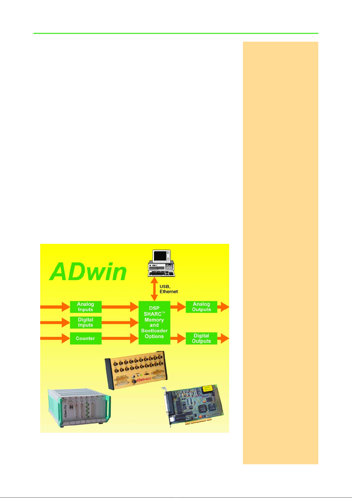
3 Operating Environment
The ADwin-Gold electronic is installed in a closed aluminum enclosure and it
is only allowed to operate it in this enclosure. With the necessary accessories
the system can be operated in 19-inch-enclosures or as a mobile system (e.g.
in cars). See also chapter 2.2.2 "Accessories").
Earth protection The ADwin-Gold device must be earth-protected, in order to
– build a ground reference point for the electronic
– conduct interferences to earth.
Connect the GND plug, which is internally connected with the ground refer-
ence point and the aluminum enclosure, via a short low-impedance solid-type
cable to the central earth connection point of your device.
Galvanic connection The power supply cable is the galvanic connection between the computer and
the ADwin-Gold.
The version with USB interface has a galvanic connection to the computer or
where appropriate also via the power supply.
The data lines at the version with Ethernet interface are optically isolated, but
the ground potentials are connected, because the shielding of the Ethernet
connector (RJ-45) is connected to GND.
Excluding transient
currents
Transient currents, which are conducted via the aluminum enclosure or the
shielding, have an influence on the measurement signal.
Please, make sure that the shielding is not reduced, for instance by taking
measures for bleeding off interferences, such as connecting the shielding to
the enclosure just before entering it. The more frequently you earth the shield-
ing on its way to the machine the better the shielding will be.
Use cables with shielding on both ends for signal lines. Here too, you should
reduce the bleeding off of interferences via the ADwin-Gold aluminum enclo-
sure by using screen clips.
BNC cables The shielding of BNC cables is normally used as differential ground and looses
therefore the shielding effect. So BNC cables are influenced by interferences
when differential measurements are executed. For signal and data transfer
outside of an enclosure it is necessary to use twisted pair data transfer cables,
whose channels are shielded, too.
Protection low voltage The ADwin-Gold is externally operated with a protection low voltage of 10V
to 35V; internally it is operated with a voltage of +5V and ±15V against GND.
It is not life-threatening. For operation with an external power supply, the
instructions of the manufacturer applies.
Ambient temperature The ADwin-Gold is designed for operation in dry rooms with a room temper-
ature of +5°C … +50°C and a relative humidity of 0 … 80% (no condensation,
see Annex).
Chassis temperature The temperature of the chassis (surface) must not exceed +60°C, even under
extreme operating conditions – e.g. in an enclosure or if the system is exposed
to the sun for a longer period of time. You risk damages at the device or not-
defined data (values) are output which can cause damages at your measure-
ment device under unfavorable circumstances.