5. Adjusting Day Program Schedules
Wiring your thermostat
WARNING: Please arrange the professional technician
to install this product according to installation drawing and
instruction.
RISK OF ELECTRICAL SHOCK. Disconnect power supply
before making electrical connection. Contact with components
carrying hazardous voltage can cause electrical shock and may
ShenZhen Toupwell Technology Co.,Ltd
result in severe personal injury or death.instruction.
www.toupwell.com
Press and hold for 3 sec., hh will flash
in the postion of hh:mm.
NOTICE: The installation wire should be 1.5-2.5mm2.
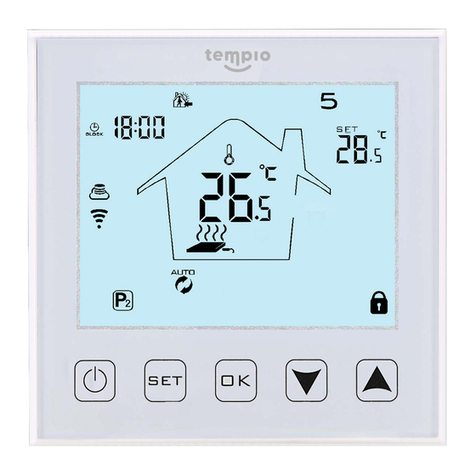
Technical Data of your thermostat
Power Supply: AC85~260V, 50/60HZ
Power Consumption: <0.5W
Current Load: 3A
Sensor: NTC
Accuracy: ±1℃
Dimension: 86*86*13.3mm (H*W*D)
Set Temp.: 10℃- 40℃
Press to adjust the hour.
Press , mm will flash in the postion of
hh:mm.
Press to adjust the minute.
Press , 1 (for example) will flash in the
postion of 1234567.
Press to adjust the week.
Press , period 1 and hh will flash.
The above is the steps to set real time.
Then go into day programmable setting.
Press to adjust the hour.
Press , period 1 and mm will flash.
Press , period 2 and hh will flash.
Press to adjust the hour.
Press , period 2 and mm will flash.
Press to adjust the minute.
Press to adjust the minute.
Press , period 3 and hh will flash.
Press to adjust the hour.
Press , period 3 and mm will flash.
Press , period 4 and hh will flash.
Press to adjust the hour.
Press , period 4 and mm will flash.
Press to adjust the minute.
Press to adjust the minute.
Press , loop will display in the screen.
One day programmable setting is finished.
Shell Material: Fireproof PC+ABS
Installation Box: 86*86mm
Working Ambient: 0~ 45 , 5~95% non-condensing.
℃
Storage Temp.: -5~55
℃
Installing your thermostat
This product is suitable for standard 86*86mm
Press to confirm the setting;
Press to confirm the setting;
Press to confirm the setting;
Press to confirm the setting;
1. Open the control board by a Flat-blade screwdriver in the
position of Fig 1.
(Fig 1)
2. Remove the cables.
(Fig 2)
3. Connect the wiring.
4. Fix the back cover by the two screws inside the box.
(Fig 4)
(Fig 3)
5.Connect the control board and back cover.
(Fig 5)
1234567
LN
FAN VALVE
AC230V, 50/60HZ
L M H
closeopen
Two Pipe Four Pipe
1234567
LN
FAN
AC230V, 50/60HZ
H M L
Cool Vlave
Heat Vlave
