SyxthSense DTP-A80-BC Dimensions

Product Sheet
TH6.21
Thermostat Type
DTPA80BC
Online Store: www.syxthsense.com
Enquiries: T: 0870 20 80 100 F: 0870 20 80 200 PS TH6.21 – 1/6
DTPA80BC Wireless Thermostats
Model Types Model Description
DTP-A80-BC
DTP-A80-BC Wireless Thermostat with Operation Mode Switch
DTP-A80-BC02 DTP-A80-BC02 Wireless Thermostat
DTP-A80-BC-TP DTP-A80-BC-TP Wireless Tamperproof Thermostat (setpoint under
cover)
Technical Data Power supply 2 x 1.5V= alkaline batteries AAA type
Batteries duration > 5 years
Regulation range 6°C .. 30°C
Accuracy ± 1°C
Hysteresis 0.3°C
Resolution 1°C
Sensor type NTC 100k @ 25°C internal
Remote sensor
(optional) STL OTS A 150
(Max. remote sensor wire length 3m)
Frequency 868.35 MHz
Modulation type AM (ASK)
Output power (ERP) < 25 mW
Antenna type: Internal
Max. distance from
receiver 30 m indoor (depending on the environment)
Storage Temperature -10°C .. +50°C
Operating Temperature 0°C .. 40°C
Protection Class IP30
Humidity Limits 20% .. 80% rH (non condensing)
Enclosure Material: ABS V0 self-extinguishing
Colour Signal white (RAL 9003)
Agency Compliance EEC 89/336, 73/23, 93/68, 99/05
This room electronic thermostat is suitable for a reliable and accurate
temperature regulation in commercial and industrial premises as well as
in home installations. Its main feature is the capability of operation
without any wire connection: the on/off commands are issued to the
receiving unit via radio signals, making this product extremely easy and
economical to install especially where no existing electrical wires are
available.
FEATURES
•Completely wireless thermostat 868.35 MHz band
•Programmable 3°C reduction
•Low battery indication
•Knob limitation feature through mechanical pins
•Fixing with distance between holes 60 mm.
•Compliant with directives EEC 89/336, 73/23, 93/68, 99/05

SyxthSense Ltd
Online Store: www.syxthsense.com Copyright ©2004 SyxthSense Ltd – 07/2004
Enquiries: T: 0870 20 80 100 F: 0870 20 80 200 PS TH6.21 – 2/6
Size 85W x 85H x 33D mm
Weight 0.13kg
Mechanical Construction
In the thermostat’s front panel shown in Fig. 1 are indicated the following:
- mode selector (1);
- red led indicator (2);
- set-point knob (3).
The mode selector (1) has three different positions:
PROGRAM: Night reduction enabled
COMFORT: Comfort position
OFF: Off position
The red led indicator (2) flashes when batteries are exhausted and gives an information about the
actual regulation when the mode selector (1) is moved. Through the set-point knob (3) the user can
set the temperature around which the regulation will take place.
To access to the internal part of the thermostat, is necessary to open the plastic case, by removing
the frontal panel. To remove it, remove first the knob using a small screwdriver, place it in the slot
(11) visible in the Fig. 3 and Fig. 4 and apply a slight pressure. Afterwards use the screwdriver to
drive the plastic teeth (4) shown in Fig. 3.
Apply a light pressure with a screwdriver between the tooth and the hole in the plastics, but do not
push directly on the tooth in order not to break it.
The Fig. 2 represents the plastic box section and it shows how to handle the screwdriver correctly.
In Fig. 5 is shown the thermostat’s internal layout:
(1)
(2)
(8)
(9)
(10)
(12)
Mode selector
Red led indicator
Battery place and polarity
External sensor input terminals
Address Dip switch
Internal Reset button
JP1
Inserted: Internal sensor enable
(default)
Removed: External sensor enabled
JP2 Inserted: 10 minutes option (default)
Removed: 3 minutes option
JP3 Inserted: Heating mode (default)
Removed: Cooling mode

SyxthSense Ltd
Online Store: www.syxthsense.com Copyright ©2004 SyxthSense Ltd – 07/2004
Enquiries: T: 0870 20 80 100 F: 0870 20 80 200 PS TH6.21 – 3/6
Operation The thermostat can control either heating or cooling systems: the selection is made by setting an
internal jumper JP3 (Fig. 5).
In ‘heating’ mode the thermostat turns on the relevant channel output relay in the receiving unit when
the room temperature is lower than the value set with the knob (3) (set-point temperature). When
temperature rises over the set value the relay will be turned off. This action will be performed with an
hysteresis of 0.3°C. The hysteresis is a fixed parameter and cannot be changed.
In ‘cooling’ mode the operation logic is inverted, when temperature rises over the set value the relay
is turned on, the relay output is meant to activate a cooling system. This action will also be
performed with an hysteresis of 0.3°C. In both modes a night reduction of 3°C is available: this option
can be activated through selector (1) by setting it in ‘Program’ position (i. e. the upper position). This
function makes the thermostat operates with both the ‘comfort’ and a ‘reduced’ set-point, in order to
get energy saving, for example during the night. In ‘heating’ mode the reduced set-point corresponds
to the comfort set-point minus 3°C. In ‘cooling’ mode the reduced set-point corresponds to the
comfort set-point plus 3°C.
When in ‘Program’ position the thermostat sends to the receiver an additional signal which lets the
receiver drive the relay output in a reduced way. This signal is called ‘reduced signal’ while the
normal signal is called ‘comfort signal’. The receiving unit can then use either the signals to drive the
relevant output.
A special input (clock input) at the receiving side makes the output be controlled from the comfort or
the reduced signal. This ability was meant to easily get a reduction during the desired hours by
connecting a clock switch to the receiver.
If there is no clock connected to the receiver, the ‘Program’ position in the thermostat will operate
with the reduced set-point at any time. For more information see the receiver documentation.
Setting selector (1) in the Comfort (i.e. the central) position will make the thermostat regulate always
at the comfort set-point without any reduction. The Off position of the selector will always keep the
relevant relay output in the Off state. Note that even in the Off mode the thermostat still transmits to
the receiver signals, which will be always Off signals. This is performed to distinguish from normal
turned off operation and the eventuality of faults on the transmitter.
The thermostat is supplied with two AAA 1.5V= alkaline batteries and the red led (2) informs when
the batteries are discharged and must be replaced. In normal operation the led is always off; on the
other hand when it indicates the low battery state it flashes once every about 20 seconds. In order to
grant a reasonable battery life the thermostat waits, between two consecutive transmissions, an
amount of time that can be set in 3 or 10 minutes by moving an internal jumper JP2 (see Fig. 5). The
3 minutes option is selected by removing JP2: this option should be chosen only with fast
heating/cooling systems. With common heating systems like floor heating systems, the 10 minutes
interval option provides a good accuracy and comfort.
System Start-Up Before installing the thermostat in the desired position, is necessary to test if the receiver unit
correctly receives its radio signals. To do this the thermostat must be turned on in a ‘Test’ mode.
The operation is described in the following.
Open the thermostat box according to the instruction in the “Mechanical description” section. Set the
appropriate address in the dip switch (10) visible in Fig. 5. The address can be chosen randomly but
taking into account that several thermostats installed in the close area must operate with different
addresses, to avoid data collision and malfunction.
See also appendix A for more information.
Insert the batteries, carefully respecting the polarity and do not use old, used, or non alkaline
batteries. When inserting the batteries for the first time the red LED (2) turns immediately on for
about 2 seconds. This displays the correct insertion of the batteries and the correct operation of the
thermostat (this can also be obtained at any time by pressing for a while the reset button (12) visible
in Fig. 5).
In the thermostat, move the selector (1) to the OFF position and just press the ’reset’ (12) button.
Now the thermostat is operating in ‘Test’ mode and this state is also displayed by the LED (2) which
flashes every 3 seconds.
During the test operation it is important not to move the selector (1), from the Off position, if it is
moved the test mode finishes. The test mode also ends automatically after about 25 minutes.

SyxthSense Ltd
Online Store: www.syxthsense.com Copyright ©2004 SyxthSense Ltd – 07/2004
Enquiries: T: 0870 20 80 100 F: 0870 20 80 200 PS TH6.21 – 4/6
System Start-Up Cont’d.. In ‘Test’ mode the thermostat continuously issues On and Off signals to the receiver every about 3
seconds. Position the receiving unit as close as possible to the desired final place. Turn on the
receiving unit and execute the self-learning procedure by pressing its relevant button. Once the
thermostat’s address has been learned, the relevant relay output should continuously toggle
between On and Off state, every 3 seconds.
This output state in the receiver is also displayed by its LED. If this happens the thermostat is
correctly communicating with the receiver. When positioning the thermostat in the desired room,
ensure that they still communicate well, checking the relevant output which should be continuously
toggled.
If the thermostat is placed too far from the receiver, the relevant relay output will not toggle and
remain stuck in the On or Off state: this means that the thermostat must be positioned in another
place, closer to the receiver or as far as possible from metal sheets or reinforced cement walls which
could weaken the radio signals. The signal quality can be monitored in the receiver unit, please see
the receiver instruction for more information.
Once the optimal position is found, move the selector (1) to the ‘Comfort’ or ‘Program’ position to
stop the test and to enable the normal operation. Proceed with the mechanical installation.
Mechanical and Electrical
Installation For installation of DTP A80 BC see the following:
Fix the thermostat base plate to the wall through the two screw holes with distance between axes of
60 mm. While operate with tools in the screw holes, be careful not to damage the internal circuits or
any other component. This thermostat does not need connection to any electrical wiring, because it
was developed to be a wireless thermostat. However it is available an external sensor input (9) Fig.
5, see “Remote sensor selection” section for further information. After inserting batteries and testing
operations, close the thermostat by carefully positioning the panel so that the knob shaft matches its
hole, then slightly press the panel in order to make the four plastic teeth snapping. Ensure that the
selector matches the relevant slot on the plastic cover. Reinsert the knob by placing it in the correct
angle so that it matches correctly its shaft, then push it until it snaps. For a correct room temperature
regulation the thermostat should be installed far from metal sheets and heat sources. Avoid to fix it
on a particularly hot or cool wall. To determine the correct position the user must be sure that the
radio signals are correctly received by the receiving unit.
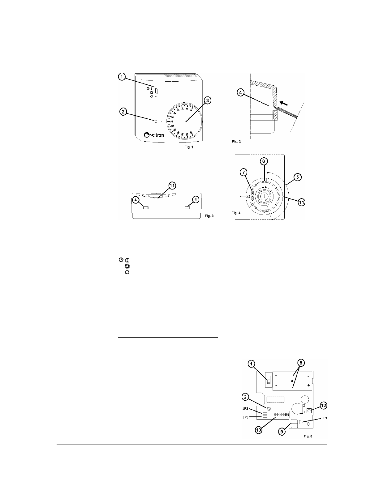
Knob Rotation Limitation It is possible to limit the rotation range for the set-point knob by following these steps:
1. Remove the knob using a small screwdriver, place it in the slot (11) visible in the Fig. 3 and Fig. 4
apply a slight pressure.
2. Pick up the plastic pins (7) parked at one side of the knob area and set them (6) as in the example
of Fig. 4. In this example the rotation range (5) is reduced as in the shown angle.
3. Reinsert the knob by placing it in the correct angle so that it matches correctly its shaft, then push
it until it snaps.
Remote sensor
selection In order to connect to DTP A80 BC a remote sensor alternative to the internal one, remove the
jumper JP1 on the thermostat board, which is located in the bottom right side of the thermostat,
underneath the set-point knob (see Fig. 5). Ensure to use the correct remote sensor type and
respect the maximum wire length, then connect it to the two terminals (9) Fig. 5. If there is no need of
external sensor, keep the jumper JP1 inserted as default, so that the internal sensor is used.
Maintenance The wireless thermostat does not need any particular maintenance operation.
The supply batteries must be replaced with new ones, when the red indicator LED (2) flashes. It
flashes once every about 20 seconds. The batteries must be always replaced even if the thermostat
is often kept turned off. To replace the batteries, open the thermostat’s plastic box, see the
‘Mechanical description’ section, remove the old batteries, ensure that the new batteries are of the
right type: two 1.5V= alkaline AAA type. Insert the new batteries respecting the polarity: the symbols
+ and - .
In Fig. 5 is visible the battery internal location (8). After inserting batteries, and also at any time, it is
possible to perform a battery-check by pressing for a while the reset button (12) visible in Fig. 5
(leaving the selector (1) in a position different from ‘Off’, otherwise the ’test’ mode is entered) .
At the reset, the red led (2) Fig. 5 turns on for 2 seconds to display the correct insertion of the
batteries and the correct operation of the thermostat. In case you want to force a temperature
sampling and transmission it is sufficient to move the selector (1) to the ‘Off’ position or from the
‘Off’ position. This will result in an immediate update at the receiving side and the type of command
(’on’ or ‘off’) is displayed through the led indicator (2): a short flash stands for an ’off’ command
meanwhile a long flash stands for an ‘on’ command.

SyxthSense Ltd
Online Store: www.syxthsense.com Copyright ©2004 SyxthSense Ltd – 07/2004
Enquiries: T: 0870 20 80 100 F: 0870 20 80 200 PS TH6.21 – 5/6
Appendix A: Dip-switch
and address setting The goal of this appendix is to give more information to know and correct handle with dip-switches.
In Fig. 5 is shown the 8 way dipswitch mounted on the internal circuit of DTP A80 BC. 8 way
dipswitch means that it is a group of 8 mini-switches. In fact each small white peg visible in its
surface is a switch. Every switch has two possible position, 0 and 1, down and up. The position can
always be changed by shifting up or down the small peg using the point of a small screwdriver.
Following there are some pictures of 8 way dip-switch with different combinations set.
In the 8 way dip-switch can be set up to 256 different combinations. In the table of Fig. 6 are shown,
as an example, all the possible combinations for the former half of the dip-switch. Those
combinations are valid even for the latter half. By the dip-switch combination a unique code called
“address” is established. The code is needed at the receiving side to identify the thermostat and to
“link” it to the desired output relay. The address has to be chosen randomly taking care that it is
different from the other thermostats’ addresses that could be installed in the same system or in the
close area.
Troubleshooting
TROUBLE SHOOTING
SYMPTOM
PROBABLE
REASON
REMEDY
In the heating mode, even if
the set-point knob is turned to
the highest temperature
position, the red LED (2) is
always turned off and the
relevant output in the receiver
unit remains Off.
The red LED (2) is not meant
to continually display the state
of the relay output. The output
relay does not switch ON
immediately, its state is
updated every interval of time
which could be 3 or 10
minutes (see ‘Operation’
section).
It’s a normal operation mode.
The batteries are discharged,
or they are inserted in a wrong
way; the polarity must be
respected.
Insert good batteries in the
correct way. ‘Maintenance’
section explain how to do this
correctly.
When the batteries are
inserted for the first time, the
LED (2) does not turn on for 2
seconds.
If the batteries were already
placed recently, due to the
very low power consumption
of the circuit, some energy is
still present even if there is not
any supply, so the thermostat
behaves like batteries were
never removed.
Press for a while the reset
button (12) Fig. 5, to restart
the internal electronic circuits.
When inserting batteries,
even pressing the reset button
(12), the LED (2) does not
turn on for 2 seconds, it just
turn on for a short flash, and
the thermostat doesn’t
operate.
The batteries are exhausted.
Insert good batteries in the
right way. ‘Maintenance’
section explain how to do this
correctly.
In test mode, the LED (2) in
the thermostat lashes
correctly but the relevant
output in he receiving unit
remains always OFF.
The thermostat’s address was
not successfully self-learned
by the receiver unit, or the
self-learning procedure has
not been performed on any
channel in the receiver unit.
Please follow the ‘self-
learning’ procedure described
on the receiver unit’s
instruction sheet in order to
‘link’ the transmitter to the
desired channel.

SyxthSense Ltd
Online Store: www.syxthsense.com Copyright ©2004 SyxthSense Ltd – 07/2004
Enquiries: T: 0870 20 80 100 F: 0870 20 80 200 PS TH6.21 – 6/6
WARNING !
- To determine the correct position one must ensure that the radio signals transmitted are
correctly received by the receiving unit.
- To adjust properly room temperature, install the thermostat far from heat sources,
airstreams or particularly cold walls (thermal bridges). When the remote sensor is used in
conjunction with the thermostat, then this note is to be applied to the remote sensor itself.
- For remote version all wirings must be made using wires with 1,5 mm² minimum section and
no longer than 3 m. Do not use same duct for signal wires and mains.
- Installation and electrical wirings of this appliance must be made by qualified technicians
and in compliance with the current standards.
Notes: In the view of a constant development of their products,
the manufacturer reserves the right for changing technical data
and features without prior notice. The consumer is guaranteed
against any lack of conformity for 24 months from the time of
delivery, according to the European Directive 1999/44/EC. The
full text of
g
uarantee is available on re
q
uest from the seller.
This manual suits for next models
2
Table of contents
Other SyxthSense Thermostat manuals
Popular Thermostat manuals by other brands

Aube Technologies
Aube Technologies EConnect Wireless Thermostat Kit TA7210 operating manual

CAME BPT
CAME BPT TH/450 GSM Installation and use manual

Lux Products
Lux Products EcoStat THC15a Installation and operating instructions

hager
hager EK053 User instructions

Hunter
Hunter 44155C Installation and operation manual

AEG
AEG FRTD 903 installation instructions