tousek Rollco LWS125/X User manual
Installation manual
Steel cantilever system Rollco®LWS 125/X

- 2 - tousek / E_ LWS-125/X_X40801104 / 22. 05. 2018
This manual is the sole property of the TOUSEK Ges.m.b.H. and may not be made available to competitors. All rights reserved. No part of it may be reproduced without our prior
written permission. We will not accept liability for any claims resulting from misprints or errors. This edition of the manual replaces all earlier publications of the same.
Important warning and safety notes for installation and operation
• These installation- and operating instructions form an integral part of the product “cantilever system”. They have been
specically written for professional installers trained and skilled in the trade and should be carefully read in their full length
before carrying out the installation. After the installation this manual has to be handed over to the user.
• Installation, connection, adjustments, putting into operation, and servicing may only be carried out by trained
professionals in full accordance with these installation- and operating instructions. Faulty assembling can
cause severe injury and material damage.
• The EU Machine Directive, laws and rules concerning the prevention of accidents, and laws and standards which are in
force in the EU and in the individual countries have to be strictly followed.
• The TOUSEK Ges.m.b.H. cannot be held liable for any claims resulting from disregards of the laws and standards in force
during the installation and operation.
• The product may only be used in accordance with its original purpose, for which it has been exclusively designed, and
which is described in these installation and operating instructions. The TOUSEK Ges.m.b.H. rejects any liability if the
product is used in any way not fully conforming to its original purpose as stated herein.
• The packaging materials (cardboard, plastic, EPS foam parts and lling material etc.) have to be properly disposed of in
accordance with the applying recycling- and environmental procection laws. They may be hazardous to children and
therefore have to be stored out of children´s reach.
• Before beginning with the installation the installer has to make sure that all mechanical components of the gate facility, like
carrier prole/rail, gate frame and panels, guiding elements etc. are sufciently supportive and resistant for the purpose
of gate automation. Check also whether the product has transport damages.
• After installation the proper function of the gate facility has to be checked!
• Place warning signs and notes of the valid regulations to indicate danger areas.
• Children have to be instructed, that the gate facility as well as the belonging parts may not be used improperly,
e.g. for playing.
• Only original spare- and replacement parts may be used for repair of the product.
• The TOUSEK Ges.m.b.H. rejects any liability for claims resulting from usage of the product in combination with compo-
nents or devices which do not fully conform to the applying safety laws and rules.
• The installer has to supply to the user all instructions relating to the safe operation of the gate facility. The installation
and operating instructions also have to be handed over to the user.
Maintenance
According to the frequency of actuation, but at least once a year, we recommend to carry out the following
maintenance works:
• Check if the rolling gears are standing in-line.
• Check if the gate is smooth running without jamming.
• Check the upper gate guiding.
• Check the assembly screws.
• Check if the door runs correctly into the guide-in bracket resp. guide-in fork bracket.
• Clean and sligthly grease the tread in the inside of the prole.
ATTENTION: blocking of the gate (see page 9) !
• Firmly bolted mechanical stops prevent the running of the sliding gate on the rolling gears, when in OPEN or
CLOSED position!
• Examples of xed limit stops as safety devices:
(1) Guide-in bracket, (2) counter pillar, (3) transverse bore and through screw (M12) in the prole

tousek / E_ LWS-125/X_X40801104 / 22. 05. 2018 - 3 -
1
2a
2b
3
4a
4b
5
1
1. General Cantilever System Rollco®LWS 125/X
Characteristics
• the perfect system for cantilever sliding gates
• steel track 125/105/5 mm
• cold rolled hot-dip galvanised steel
• drilling channel for easier gear rack mounting
• tracks in four different lenghts
• load weight up to 150kg/running meter
• gate cycles: approx. 200/day
• rolling gear, galvanised with ball bearing rollers
and plastic covers
•
Legend:
(1) rolling gear
(1a) roller cover
(2a) end plate
(2b) end plate with roller
(3) guide-in bracket
(4a) stop for CLOSE movement
(4b) stop for OPENING movement
(5) underlying plate
(6) cantilever track
General
The steel cantilever system Rollco®LWS 125/X is the perfect
system for cantilever sliding gates. Modern cantilever sliding
gate constructions have the advantage that the gate moves
easily over any ground uneveness. The massive roller with
large, ball-bearing steel wheels enables optimal guidance and
guarantees even with maximum load and big and heavy gates
a smooth and reliable gate movement. The adjusting bolts on
the rollers prevent a tilting effect from load capacity changes
during gate movement.
As the rollers do not guarantee a vertical gate guidance
please ensure that appropriate guidance brackets are
included on site.
5
1
105mm
125mm
140mm
max.35mm
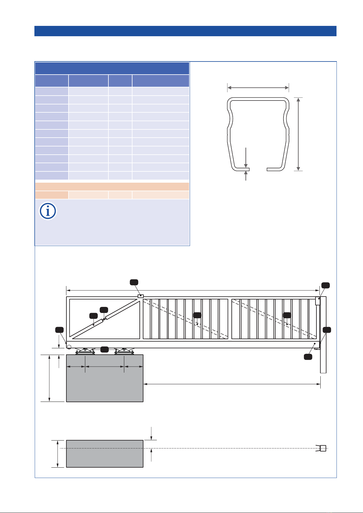
Technical Data
Steel track Rollco®LWS 125/X Art.No.
Steel tracks load capacity: up to 150kg/m, weight: 15kg/m
for max. DL 5.000mm 7.100mm steel track 14620230
for max. DL 6.000mm 8.500mm steel track 14620240
for max. DL 7.000mm 10.000mm steel track 14620250
for max. DL 8.500mm 12.000mm steel track 14620260
rolling gear LWS 125/X
2 units necessary, adjustable in height and inclination, steel rollers, galvanised,
incl. plastic cover and heavy load anchor and stainless steel plate,
gate cycles: approx. 200/day
14620290
ATTENTION: the assembly and installation of the gate and cantilever system may only be carried out by trained
and qualied staff. For perfect function and avoiding damages at the cantilever system, the following planning-
and processing rules have to be strictly followed!

- 4 - tousek / E_ LWS-125/X_X40801104 / 22. 05. 2018
Important
• The cantilever track is made of hot-dip galvanized strip steel. It may in no case be additionally hot-dip galvanized
later, since this would lead to damages. For reasons of production the cut surfaces are not galvanized, and
therefore have to be foreseen with an according rust protection.
• If the gate frame is welded on the cantilever track please make sure that the cantiliever track does not have any
distortion.
• When using different materials (e.g. aluminium gate frame), an anti-corrosion contact tape has to be set in
between gate frame and cantilever system.
• The gate frame may not show any distortion.
• In the area of the support length, a diagonal tie (Z) has
to be inserted. From 5000 mm DL and upwards, this tie
has to be adjustable.
• the max. loading per run. m should not be exceeded,
please see table (p. 5) .
• For relieving the gate in position “CLOSED”, an end plate with support roller and a guide-in bracket have to be
mounted. From a clearance width of 5 m on, this should also be foreseen for gate position “OPENED”.
• For the upper gate guiding, guide brackets with rollers and a guide-in fork bracket in gate position “CLOSED”
have to be foreseen.
• Recommended pipes for the gate frame:
clearance width DL gate frame
tube gate bars
up to 5000mm FR 60/60/3 FR 25/25/2
5000–7000mm FR 80/80/3 FR 30/30/2
> 7000mm FR 120/80/3 FR 30/30/2
These specications are only standard values, the gate has to be constructed according to the static requirements.
• Load through wind: The calculation of the cantilever system is based on a gate with bars or lattice.
No wind-impermeable materials may be used as gate-lling.
• The measurements for the foundation are only standard values. The foundation always has to be adjusted to
the structure of the ground. It should consist of concrete quality C20/25 at ground class 3. The foundation has
to be horizontal and free of cracks.
A reinforcement (armour iron) may only be carried out from 200 mm upper concrete edge (heavy-lift dowels).
• These technical notes are only valid for horizontally running gates.
ATTENTION: blocking of the gate (see page 9) !
• Firmly bolted mechanical stops prevent the running of the sliding gate on the rolling gears, when in OPEN or
CLOSED position (see page 9) !
Taking into operation
After installation and before taking into operation, the following points have to be carried out::
- Clean the inside of the cantilever system (remove possibly existing swarfs)
- Slightly grease the prole in the area of the tread of the rollers.
- Check if the gate is smooth running without jamming.
Maintenance
According to the frequency of actuation, but at least once a year, we recommend to carry out the following
maintenance works:
- Check if the rolling gears are standing in-line.
- Check if the gate is smooth running without jamming.
- Check the upper gate guiding.
- Check the assembly bolts
- Check if the door runs correctly into the guide-in bracket resp. guide-in fork bracket.
- Clean and sligthly grease the tread in the inside of the prole
DL up to
5000mm
60
60
3
80
80
DL 5000-
7000mm 3
80
120
DL >
7000mm 3
Z D D
(Z) diagonal tie
(D) diagonal tie
tousek / E_ LWS-125/X_X40801104 / 22. 05. 2018 - 5 -
Measurements table Rollco®LWS 125/X measures in mm
DL track length L Em max. load weight
3500 5000 850 150kg/m
4000 5700 1050 150kg/m
4500 6400 1250 130kg/m
5000 7100 1450 130kg/m
5500 7800 1650 120kg/m
6000 8500 1850 120kg/m
6500 9200 2050 110kg/m
7000 10000 2350 110kg/m
7500 10600 2450 100kg/m
8000 11300 2650 100kg/m
8500 12000 2850 90kg/m
higher load with less entrance width:
9100 12000 2250 60kg/m
NOTE:
total length L = prole length + 10mm
The track LWS 125/X is available in the
following stock lengths:
7.100, 8500, 10.000 and 12.000mm
Em
support length
entrance width DL
total length L
450
gate axis
INSIDE
325
800
min.
150 min. = minimum distance between foundation end
and middle of track (anchor bolt rmness)
325
ca. 110
measures in mm
2 2
3
5
4
6
ZD D
1
2. Installation Steel cantilever system Rollco®LWS 125/X
Foundation and installation plan
Legend:
(1) rolling gear
(2) end plate
(3) guide-in bracket
(4) guide-in fork bracket
(5) turnbuckle
(6) guide bracket
(Z) diagonal tie
(D) diagonal tie
125
105
5
- 6 - tousek / E_ LWS-125/X_X40801104 / 22. 05. 2018
2
2
1
1
gate bodywork
max. 12mm
hexagon socket bolts
M12, min 8.8
3
AS AS
at the beginning and end of fra-
me (bodywork) 3x bolts !
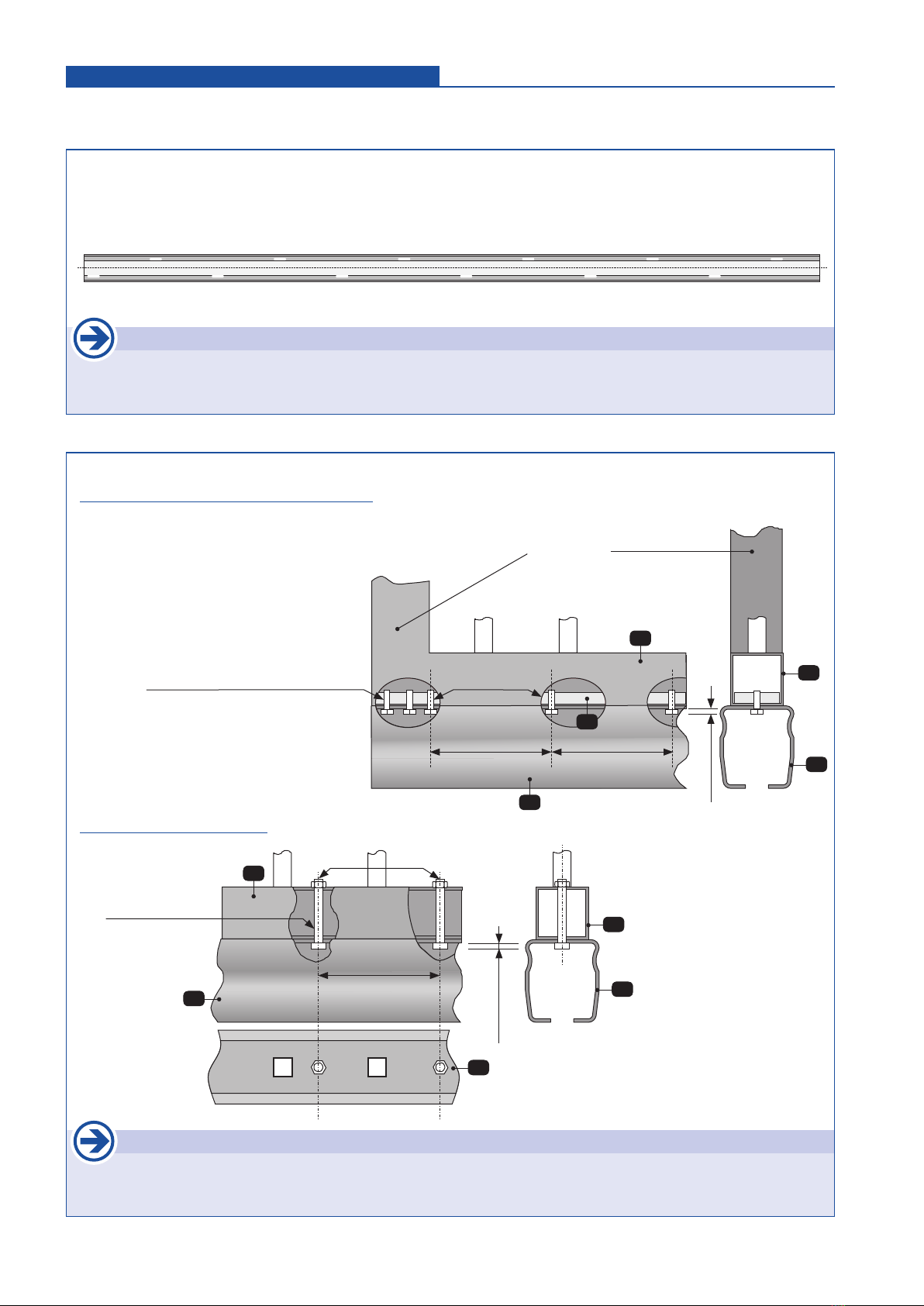
Important
• the distance AS between bolts is depending on entrance width and load weight (250–500mm).
• the cantilever track and gate frame must be connected with each other in a xed way!
Version: transparent bolt-on mounting
• at steel with threaded holes versehen.
• assign bore holes onto cantilever track and
forming tube, then drill the holes.
• insert at steel into the forming tube, correct
positioning and then weld.
• bolt the track with the gate bodywork.
Version: through bolts
2a. Connection of track with frame Mounting
Bolt-on mounting
Legend:
(1) track
(2) forming tube as required
(3) at steel
Important
• the welding of the frame body with cantilever track should never be done with the rolling gears inside as this
would lead to damage of rollers!
• If the cantilever track is welded with the gate frame the following welding seams are sug-
gested (to prevent distortion of track): 1 - 1 - 1..., 2 - 2 - 2..., 3 - 3 - 3... etc. (see picture).
The welding seams have to be conducted following the static requirements.
Mounting through welding
1 3 2 1 3 2
2 1 3 2 1 3
max.12mm
distance Ø17/3
welded on
AS
2
2
1
2
1
hexagon socket bolts
M12, min 8.8
tousek / E_ LWS-125/X_X40801104 / 22. 05. 2018 - 7 -
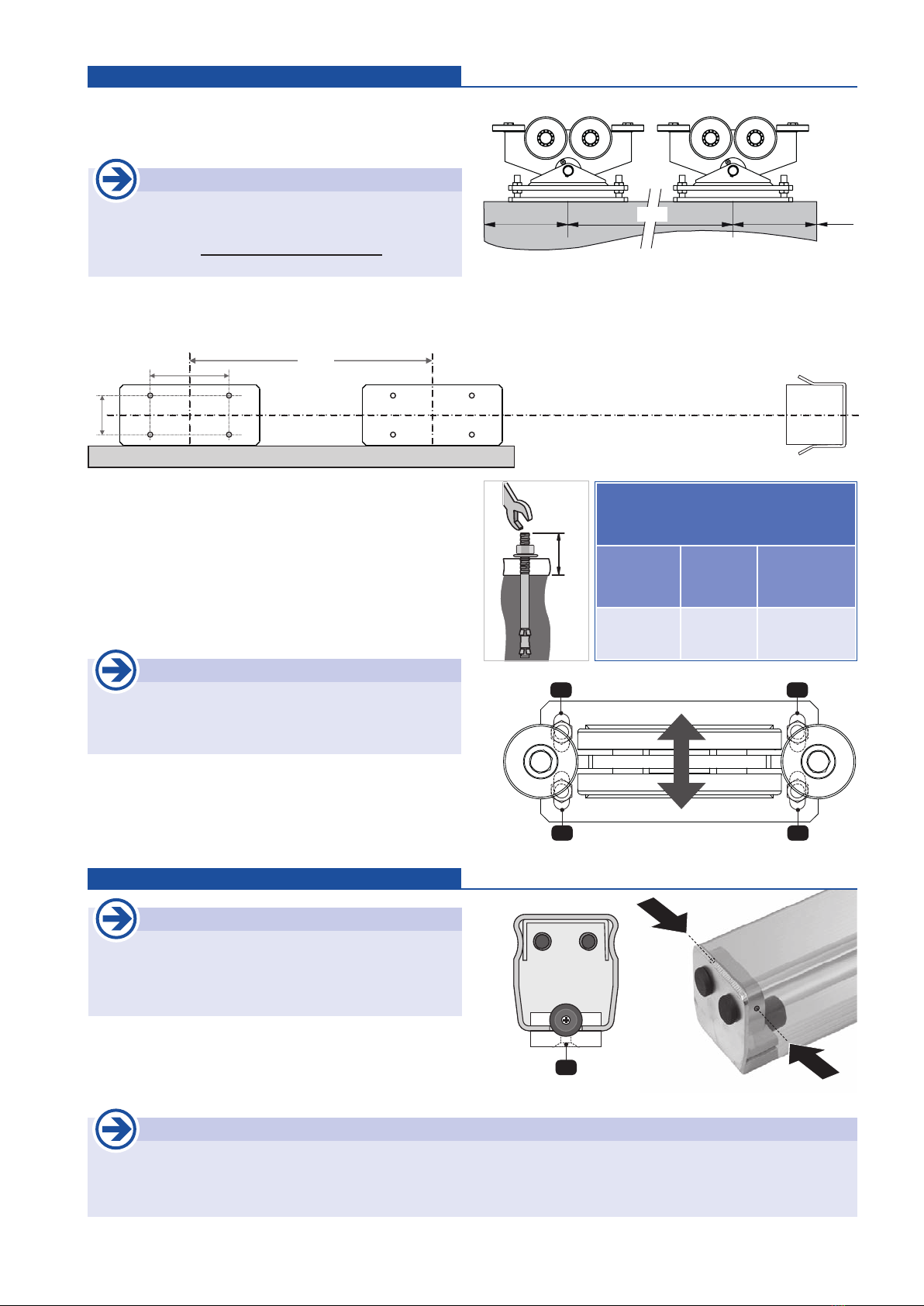
2b. Mounting of rolling gear (rollers) Mounting
• Put up the 2 rolling gears and base plates according to the
drawing and following Em measure. Put the rolling gears
in-line with the planned gate axis and mark the drill holes.
Important
• The support length Em may not be lower than given
in the table (p. 5)
• Respect the accurate to side alignment of rolling
gears (see pict.)
• For installation the upper parts of the rollers must be unbolted from the lower plates. The ground plates have to placed ac-
cording to the measure Em and aligned to gate axis. Then assign/draw bore holes for heavy load anchor bolts.
30
• draw the bore holes. After drilling blow out holes and insert
anchor plugs. Please use only heavy load anchors.
• now mount the two ground plates with anchor bolts.
• place the upper parts of rollers and x them with nuts in
middle position of sloted holes (L1–L4).
• now slide the cantilever track with the gate onto the rolling
gears. If necessary it is possible to make readjustments
(height adjustment or adjustment in sloted holes L1–L4).
Important
• As the rollers do not guarantee a vertical gate
guidance please ensure that appropriate guidance
brackets are included on site.
2c. Befestigung der Endplatten Montage
Important
• before mounting the end plates please provide
rust protection on the cut surface as they are not
galvanised when leaving factory.
• loosen the clamp bolt (K) of end plates and then insert the
end plates into the track. We also suggest to x the end
plates with two side bolts. K
Important
• the cantilever track opens slightly at the ends when coming out of factory. When tightening the side bolts the track
prole will be tighten together. This additional xing is absolutely essential when using the end plates also as
limit stops!
L1 L2
L3 L4
aluminium plate
guide in bracket
gate axis
180 Em
90
325 Em DL
325
Anchor M12-50/145 (M12 x 145)
bore hole
depth Ø hole nut torque
120mm 12mm 50Nm

- 8 - tousek / E_ LWS-125/X_X40801104 / 22. 05. 2018
with steel gear rack
• the steel gear rack has to be mounted onto the cantilever track with the bolt spacers (distance sleeves) and bolts
M8 x 45 (incl. with delivery).
B
203
25
12
max.
35
42
120
126
140
D
Z
139,5
163
Important
• with steal gear rack please
use the edged mounting base
plate.
2d. Mounting of gear rack Mounting
• the drillings for mounting the gear racks have to be effected
along the channel (B) in the according gaps.
• then cut thread M8 for mounting of gear rack into track
prole.
• check the installation of the gear rack in the corresponding
sliding operator manual!
B
Important
• drilling on the cantilever track should only be ef-
fected along the drilling channel (B).
• make sure that before mounting the gear rack the
mounting bolts should go max. 3mm inside!
• clean the track befor moving the gate!
max.
3mm
Installation example Rollco® LWS 125/X and sliding gate operator PULL T
(B) drilling channel
(D) bolt spacer
(Z) steel gear rack
form tube
60 x 60 x 3, 80 x 80 x 3,
or 120 x 80 x 3

tousek / E_ LWS-125/X_X40801104 / 22. 05. 2018 - 9 -
A
A
2e. Mounting of limit stops Mounting
• for operators without limit switches(operators with electronic
path measurement): the rubber limit stops are being installed
on the proles so that the limits OPEN and CLOSED are
dened through an impact on the rolling gear.
• the 2 metal parts of the limit stops (A) have to be mounted
underneath the prole with bolts (K) (Rubber bumper must-
show in direction of the rolling gear, see picture).
K
K
A
Important
• Limit stops (A) must be
installed !
3 3
rolling gears
ATTENTION: blocking of the gate
• Firmly bolted mechanical stops prevent the running of the sliding gate on the rolling gears,
when in OPEN or CLOSED position!
• The sole end stops, clamped to the prole (A), are not sufcient for this
purpose.
• Examples of xed limit stops as safety devices:
(1) Guide-in bracket, (2) counter pillar, (3) transverse bore and through screw (M12) in the
prole
1
3
1 1
rolling gears
1 2
rolling gears
rolling gears

- 10 - tousek / E_ LWS-125/X_X40801104 / 22. 05. 2018
3. Dimensioned drawing (measures in mm) Steel cantilever system Rollco®LWS 125/X
Roller Rollco®LWS 125/X Track Rollco®LWS 125
End stops
Rollco®LWS 125
End plate with roller Rollco®LWS 125
End plates Rollco®LWS 125
Guide-in bracket Rollco®LWS 125
We reserve the right to change dimensions and
technical specications without prior notice.
150
120
145
110
115
65
80
105
1254525 12
125
105
1512525
12
125
105
5
63,5
Bohrrille
120
Ø115
140
320
140
12
70
35 max.
405
Ø86
70
90
140
180
273
60
Ø14 (4x) M16 (4x)
197,5
foundation plate
18
24


tousek PRODUCTS
• slidinggateoperators
• cantileversystems
• swinggateoperators
• garagedooroperators
• foldingdooroperators
• tracbarriers
• carparkmanagementsystem
• windowoperators
• domelightoperators
• slidingdooroperators
• electroniccontrols
• radioremotecontrols
• keyoperatedswitches
• accesscontrol
• safetydevices
• accessories
your service partner:
Tousek Ges.m.b.H.Austria
A-1230Vienna
Zetschegasse1
Tel.+43/1/6673601
Fax+43/1/6678923
Tousek GmbHGermany
D-83395Freilassing
TraunsteinerStraße12
Tel.+49/8654/7766-0
Fax+49/8654/57196
Tousek BeneluxNV
BE-3930Hamont-Achel
Buitenheide2A/1
Tel.+32/11/916160
Fax+32/11/968705
Tousek Sp. z o.o.Poland
PL43-190Mikołów(k/Katowic)
Gliwicka67
Tel.+48/32/7385365
Fax+48/32/7385366
Tousek s.r.o.CzechRepublic
CZ-13000Praha3
Jagellonská9
Tel.+420/2/22090980
Fax+420/2/22090989
Wereservetherighttochangedimensionsand/ortechnicalspecicationswith-
outpriornotice.Claimsresultingfrommisprintsor errorscannotbeaccepted.
tousek
E_ LWS-125/X_X40801104
22. 05. 2018
Table of contents
Popular Industrial Equipment manuals by other brands


ABB
ABB GridShield 3P Installation, operation and maintenance manual

Alemite
Alemite Carbon Shield CS-5700 Series Installation, operation and maintenance manual

Hydac
Hydac VMU Series Operating and maintenance instructions

Arcteq
Arcteq AQ 1000 instruction manual

REHOBOT
REHOBOT DO111A instructions

Bühler technologies
Bühler technologies GAS 222.21 manual


