Tow Tuff TMD-75ETD User manual

Adjustable Electric Trailer Dolly
7,500lbs. Load Capacity
OWNER’S MANUAL
Model# TMD-75ETD
WARNING:
Carefully read and understand all ASSEMBLY AND OPERATION INSTRUCTIONS
before operating. Failure to follow the safety rules and other basic safety precautions
may result in serious personal injury.
07282023

Thank you very much for choosing this product! For future reference, please complete the owner’s
record below:
Model: # TMD-75ETD Purchase Date: _______________
Save the receipt, the warranty, and these instructions. It is important that you read the entire manual
to become familiar with this product before you begin using it.
This product is designed for certain applications only. The manufacturer cannot be responsible for
issues arising from modification. We strongly recommend that this product not be modified and/or
used for any application other than that for which it was designed. If you have any questions relative
to a particular application, DO NOT use the product until you have first contacted us to determine if it
can, or should, be performed on the product.
For technical questions, please call 1-218-943-6290.
INTENDED USE
Tow Tuff brings the easy way to move trailers with the TMD-75ETD heavy-duty adjustable trailer
dolly with 4 casters. This adjustable trailer dolly is the perfect way to move trailers into storage,
through tight areas, & in spaces that are hard to drive. The 7,500 lb. Capacity of this dolly allows you
to easily move a wide variety of trailers. The handlebar and built-in 24V battery and 800w motor
eliminates the need to bend over altogether! With exceptional power, control, durability, and
duration, the TMD-75ETD is perfect for moving further distances easily and comfortably with just the
pull of a trigger.
TECHNICAL SPECIFICATIONS
GENERAL SAFETY RULES
WARNING:
DO NOT ride on the dolly! No persons should ride on the dolly.
WARNING:
DO NOT ride on the dolly! No persons should ride on the dolly.Failure to follow all instruc-
tions listed below may result in serious injury.
1. Always know your dolly. Take time to fully read the installation and operator's guide in order to
understand your dolly and its operations.
2. Never store battery pack in a tool box or box with nails, screws, keys, etc. Shorting of battery
terminal may cause fire.
3. Always avoid contact with battery fluid, which may occur under extreme use or temperature-
conditions.
4. Always dispose or recycle battery according to local ordinances/regulations.
5. Always protect terminals with insulating tape, prior to disposal, to prevent shorting.
6. Never attempt to disassemble the battery. Battery is sealed.
2 of 14
Item
Capacity
Power Supply
Hitch Ball installed
Dimensions
Description
Trailer Weight: 7500 lbs Tongue Weight: 1000 lbs evenly distributed
DC24V, 9Ah
2” , 2-5/16" included option
60"x28"x39"

7. Never charge damaged battery packs, replace damaged pack immediately. Battery short or
fire may result.
8. Never incinerate the battery pack even if it is severely damaged or is completely worn out.
9. Never operate trailer dolly in an environment containing explosive or combustible material.
10. Always remove the battery when the unit is not in use for extended periods.
11. Always use Tow Tuff charger to charge lead-acid battery pack, Other types of batteries may-
burst causing damage and injury to person.
12. Never operate charger with damaged cord or plug. Replace immediately.
13. Never use Tow Tuff charger to charge other batteries.
14. Never operate charger if it has received a sharp blow, been dropped or otherwise damaged in
any way.
15. Never charge battery in damp or wet environments. Do not cover the charger with clothes or
similar items during charging.
16. The use of accessories which are not recommended or supplied by the charger manufacturer
may present a risk of fire, electric shock or personal injury.
17. Always charge battery at temperatures between32°F-120°F (0°C-49°).
18. Always store battery at temperatures between 32°F-86°F (0°C-30°C).
19. Always disconnect charger when battery is fully charged.
20. Do not leave the charger plugged in with batteries connected.
21. Always charge battery every three months if not in use.
22. Do not exceed the maximum capacity of the trailer dolly: Trailer weight: 7500lbs, tongue
weight: 1000lbs weight evenly distributed.
23. Make sure the hitch ball and the coupler are locked securely before use
24. Always use factory approved mounting hardware, components, and accessories.
25. Do not use the dolly on the downhill slope, always make sure that the road is flat, and the
slope angle is less than 4 degrees when pulling uphill.
26. Do not use dolly to move people.
27. Do not operate this dolly under the influence of alcohol or drugs.
28. Be sure to remove any elements or obstacles that may hinder the safe operation of the dolly.
29. When installing, assembling, repairing or not using the dolly, be sure to disconnect the power-
supply of the dolly.
30. Never operate or install the trailer dolly without reading or understanding the operator's
manual.
31. DO NOT allow children to operate this dolly.
32. DO NOT charge batteries more than 4-5 hours at a time.
CAUTION:
Do not allow persons to operate or assemble this Adjustable Electric
Trailer Dolly until they have read this manual and have developed a thorough understand-
ing of how the Adjustable Electric Trailer Dolly works.
WARNING:
The warnings, cautions, and instructions discussed in this instruction manual
cannot cover all possible conditions or situations that could occur.It must be under-
stood by the operator that common sense and caution are factors that cannot be built into
this product, but must be supplied by the operator.
3 of 14

SAVE THESE INSTRUCTIONS
WORK AREA
• Keep work area clean, free of clutter, and well lit. Cluttered and dark work areas can cause
accidents.
• Keep children and bystanders away while operating the adjustable electric trailer dol-
ly.Distractions can cause you to lose control, so visitors should remain at a safe distance from
the work area.
• Be alert of your surroundings. Using the adjustable electric trailer dolly in confined work areas
may put you dangerously close to sharp tools and rotating parts.
PERSONAL SAFETY
• Stay alert, watch what you are doing, and use common sense when using the adjustable elec-
tric trailer dolly. Do not use the adjustable electric trailer dolly while you are tired or under the
influence of drugs, alcohol, or medication. A moment of inattention while operating the adjust-
able electric trailer dolly may result in serious personal injury.
• Dress properly. Do not wear loose clothing, dangling objects, or jewelry. Keep your hair, cloth-
ing, and gloves away from moving parts. Loose clothes, jewelry, or long hair can be caught in
moving parts.
• Use safety apparel and equipment. Use safety goggles or safety glasses with side shields that
comply with current national standards or, when needed, a face shield. Use a dust mask if work-
ing in dusty work conditions. This applies to all persons in the work area. Also use non-skid,
safety shoes, hard hats, heavy-duty gloves, dust collection systems, and hearing protection
when appropriate.
• DO NOT ride on the dolly! No persons should ride on the dolly.
Adjustable Electric Trailer Dolly USE AND CARE
• Do not modify the Adjustable Electric Trailer Dolly in any way. Unauthorized modification
may impair the function and/or safety and could affect the life of the equipment. There are spe-
cific applications for which the adjustable electric trailer dolly was designed.
• Always check for damaged or worn-out parts before using the Adjustable Electric Trailer
Dolly. Broken parts will affect the adjustable electric trailer dolly operation. Replace or repair
damaged or worn parts immediately.
• Do not exceed the Adjustable Electric Trailer Dolly load capacity.
• Distribute the load evenly. Uneven loads may cause the adjustable electric trailer dolly to tip,
resulting in personal injury to the operator or others.
• Use the Adjustable Electric Trailer Dolly on flat and level surfaces capable of supporting the
adjustable electric trailer dolly and its maximum load. Pulling or pushing a load on a slanted or
uneven surface can result in loss of control.
• Store idle Adjustable Electric Trailer Dolly. When the adjustable electric trailer dolly is not in
use, store it in a secure place out of the reach of children. Inspect it for good working condition
prior to storage and before re-use.Remove batteries if not being use for an extended period of
time.
Main Use
The electric power dolly is compact in structure and convenient in operation. It is used for towing
trailers, RVs, etc. equipped with ball head couplings. It has the functions of forward, backward and
basic steering. It is intended for movement of trailers over short distances or in compact.confined
spaces. 4 of 14
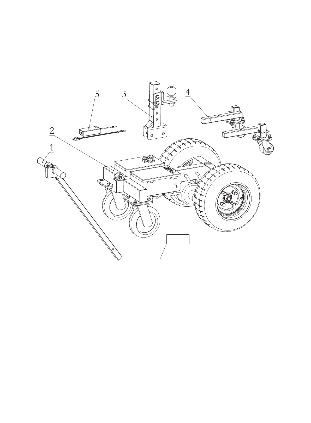
All UNITS COME WITH
1. Handle bar assembly*1
2. Dolly body*1
3. Hitch ball adjusting stem assembly*1
4. Rear support assembly*2
5. Charger assembly*1
6. Accessory kit (pin assembly*2, square pin*2, bolt M10×55*1, nut M10*1, and domed plug*1)
5 of 14
Fig. 1
6

6 of 14
STRUCTURE INTRODUCTION
1. Start switch: Control the dolly to move "forward" or "backward"
2. Transformer: Voltage conversion, 24V to 12V
3. Controller: A device to preset instructions
4. 7-core socket: Provide 12V power supply to the electromagnetic brake.
5. Power wheel: Transmit the traction
6. Adjusting stem: Adjust the position of the hitch ball forward and backward as well as up and
down
7. Hitch ball: To be connected with the trailer coupler
8. Frame nut: Used when the hitch ball is installed in a low position
9. Rear support bar: Prevent the equipment from tipping
10. Universal wheel: Control the direction of traveling
11. Charger: INPUT100~240VAC, OUTPUT: DC28.8V- 2.0A
12. Batteries: Two 12V 9AH lead-acid batteries
13. DC charging socket: For the charger
14. Power switch: Turn "on" or "off" the main power. When the vehicle is not working, please
disconnect the power
15. Voltage and battery level indicator: Indicate the voltage and battery level of the battery
16. Rear axle motor assembly: Source of power
Fig. 2
7 of 14
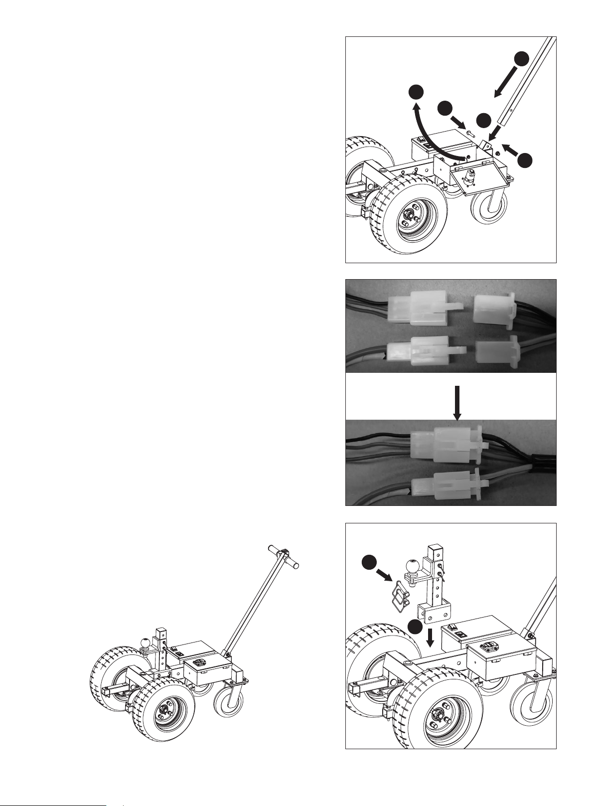
Fig. 3
ASSEMBLY
1. Installation of the handle bar assembly
(See Fig.3)
Open the lid of the control box, thread the
handle assembly (4#) lead through the square
opening at the front of the frame (#23)(Step
1) and lead it out through the large round hole
on the side of the control box (#14) (Step 2).
Insert the handle bar(#4) (Step 3), align with
the holes and insert the bolts M10x55 (#46)
(Step 4), and tighten the M10 nuts (#25)
(Step 5).
2. Connection of connectors (See Fig.4)
Connect the handle bar leads to the corre-
sponding 2P and 3P connectors.
3. Installation of the hitch ball adjusting stem
assembly (See Fig.5)
Align the Bracket of the hitch ball adjusting
assembly with the frame and select appropriate
holes (15#)(Step 1), insert Square pin(18#
)(Step 2) .
1
4
3
5
2
Fig. 4
Fig. 5
2
1
8 of 14
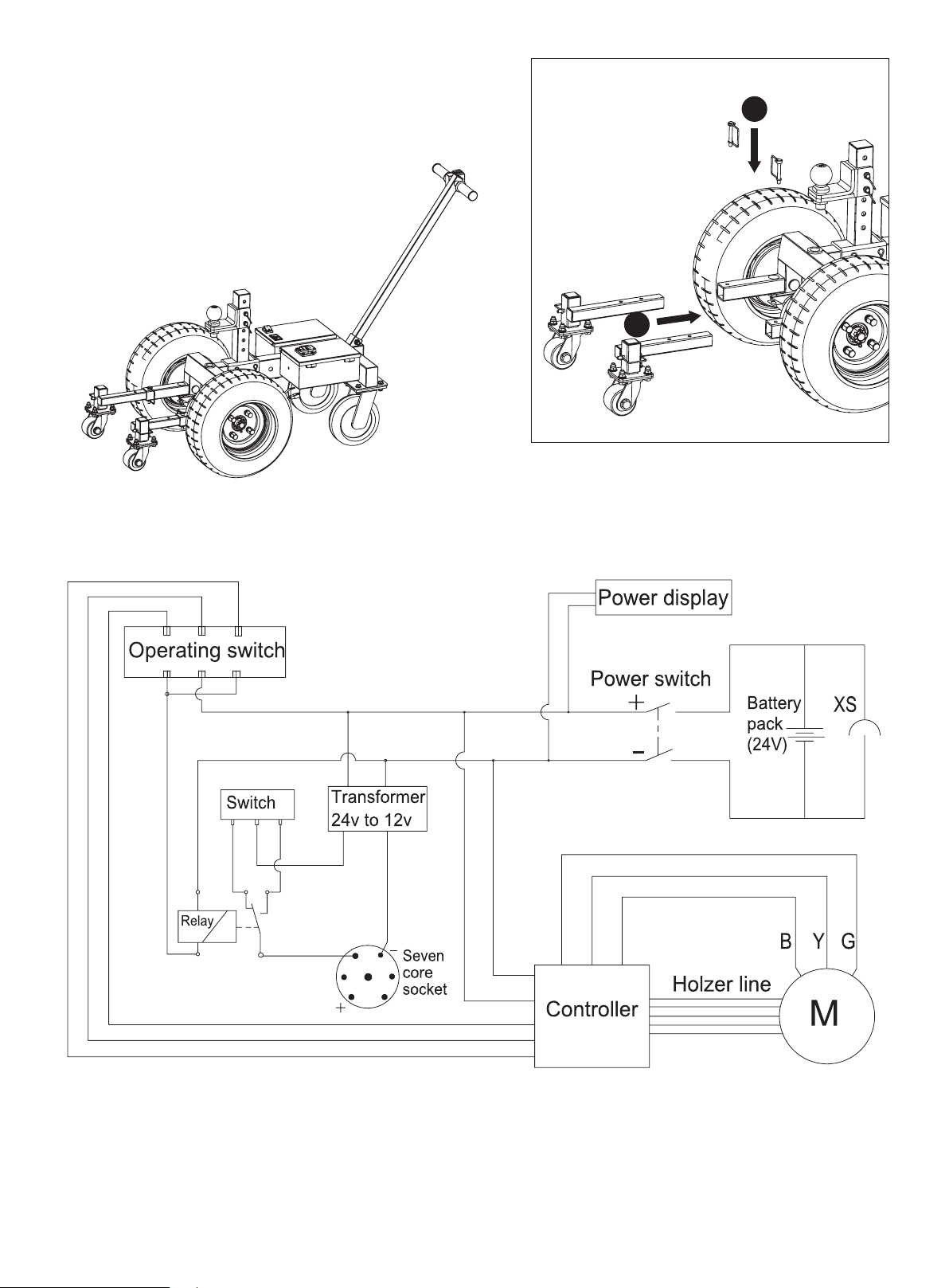
Fig. 6
4. Installation of the rear support assembly
(See Fig.6)
Insert the two rear support assemblies into the
square holes of the frame (26#) respectively
(Step 1), align the holes at the right
positions and insert the 8×60
square pins (29#) (Step 2).
5. Battery cable connection (See Fig.7)
2
1
Fig. 7
Electrical Schematic Diagram

9 of 14
CABLE SCHEMATICS
OPERATION
Commissioning and preparations
1. Before operation, check that all bolts are securely tightened, and the hitch ball stem is Securely
fastened to your desired position and locked.
2. Make sure that the tires are not cracked, bulging or otherwise defective, and that the tire pressure
is maintained at 60±2psi (4.2±0.1kgs/cm²)..
3. Make sure that the battery has sufficient power. Check that the switches work and can be
smoothly operated.
4. Test the dolly with no load to confirm that the universal wheels rotate flexibly, go forward and
backward freely.
5. Make sure that the weight of the pulled trailer is less than the maximum bearing capacity of the dolly.
6. Check that the hitch ball and the trailer coupler are tightened and that the brake control system is
reliably working before attaching the trailer.
7. Make sure the working road surface is level and less than 4 degrees grade.
Attention:
1. Connect the terminals that are highlighted in blue above before first operating trailer dolly
2. Toggle the Start Switch forward and reverse to check if the electronic brake system of trailer
functions correctly, if not toggle the Brake Switch that is highlighted in red and check again
until electronic brakes function correctly.
Start switch
Transformer
Controller
7-core
socket
Batteries
DC charging
socket
Battery level
indicator
Power switch
Motor assembly
Relay
brake switch

10 of 14
Operation of Electronic Brake System
1. Trailers equipped with Electronic Brake System can operate the electronic brakes via the start
switch
2. Trailer dolly operator must connect the 7-Pin plug from trailer to the
7-core socket on trailer dolly in order to operate the electronic brake
system on trailer.
3. The electronic brakes should release when the Start Switch is
toggle forward or reverse, when start switch is released the brakes should be applied.
4. If the electronic brake system does not function correctly when operating the start switch, open
control box and toggle the Brake switch position. Check brake function to see if the brakes func-
tion correctly
WARNING: When trailer dolly is not in use, disconnect the 7-pin plug from trailer dolly to prevent
battery drainage.
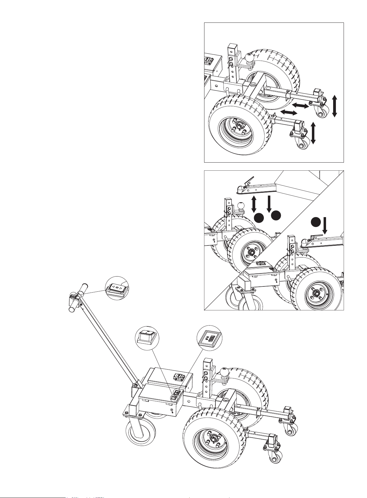
Selection of hitch ball position
1. In order to ensure that the dolly operates with the maximum traction and sufficient friction is main-
tained between the wheels and the ground, please select the appropriate hitch ball position
according to the use scenario. As shown in the figure, when the machine travels in the D direc-
tion, please put the hitch ball adjusting stem at the Gear A position; when it travels in the R direc-
tion, please put the hitch ball adjusting stem at the Gear B position. (See Fig.8)
2. The hitch ball height of the dolly can be adjusted up and down (Figure a), or the hitch ball can be
installed directly on the main frame (Figure b), with the lifting range of the hitch ball
height:17.2″-25.6″. When installing the trailer, always make sure the trailer tongue is parallel to
the ground, because any tilt will affect the traction efficiency and even the safety risk of overturn-
ing (Figure c). (See Fig.9)
D
AB
R
Fig. 8
Fig. 9
Fig. b
Fig. a
Fig. c
Switching
11 of 14
3. The rear support wheel assembly is intended to
provide support and increased stability during
towing., and depending on ground conditions,
the position can be adjusted up and down as
well as forward and backwards relative to the
main wheels. DO NOT operate trailer dolly
without the support wheel assembly properly
attached and secured in place.
(See Fig.10)
Towing Procedure
1. First move the dolly near the trailer coupler of
the trailer, and adjust the height of the hitch ball
according to the height of the trailer coupler,
until the hitch ball is slightly lower than the trail-
er coupler. Move the dolly so that the hitch ball
and the trailer coupler are lined up (Step 1),
lower the trailer slowly via the jack until the trail-
er jack coupler fully engages with the hitch ball
(Step 2), and lock the safety hook after making
sure that the hitch ball and the trailer coupler
are connected securely (Step 3). (See Fig.11)
2. Turn on the power switch (Step 1) and check if
the voltage and battery level indication is full
(Step 2). Press the start switch in the same
direction as the dolly (Step 3) and then the vehi-
cle starts to move slowly at a speed of 1.5km/h.
(See Fig.12)
Fig. 10
Fig. 11
123
Fig. 12
Start switch
Power switch
Voltage and
battery level
indicator

12 of 14
3. Shut down the power after use. And park the dolly in the correct position. Please maintain the
battery charge level. BATTERY CHARGE LEVEL MUST BE MAINTAINED REGULARLY
OTHERWISE THE LEAD ACID BATTERY MAY BECOME FULLY DISCHARGED,
RESULTING IN DAMAGE TO THE BATTERY OR FAILURE FOR IT TO MAINTAIN ANY
CHARGE.Do not charge batteries more than 4-5 hours at a time. Damage to the batteries can
occur.
OVERLOAD PROTECTION
The dolly is equipped with overload protection system, which will shut down the dolly when it detects
an overload situation. This protection is for both user and the product. To prevent the potential risk
of damage or destruction of the machine, or injury to the operator.. Please do not try to start when
the dolly overloaded and shut down, please re-start after the loading weight has been reduced to
within the max rated capacity of the product.
TROUBLE SHOOTING
MAINTENANCE
1. For storage, the product shall be stored in a cool, dry and dust-free place, to avoid direct
sunlight and rain.
2. During transportation, loading and unloading of the product, it is prohibited to cast, drop, throw
the dolly.
Problem(s)
Power dolly does not work
Power dolly stops during
operation.
Possible Cause
Power shut down.
1. Batteries are low.
2. Power dolly
overloaded.
Corrective Action
1. Check the battery status make sure it is full.
2. Check the power switch is in the power on status.
3. Check the connection cables tighten as needed.
1. Charge the battery.
2. Reduce the load within the capacity of
the dolly and re-start.

13 of 14
DIAGRAM & PARTS LIST

14 of 14
Part No.
1
2
3
4
5
6
7
8
9
10
11
12
13
14
15
16
17
18
19
20
21
22
23
24
25
26
27
28
Description
Handle sleeve
Start switch
Switch box
Handle bar assembly
Hex nut M24×3
Split pin 4×50
Nut M14×1.5
Power wheel 16.5×6.5-8
Controller 24v 800w
US-style 7-core socket
Screw assembly M5×16
Holder
Binding post
Control box assembly
Adjusting stem assembly
Hitch ball mount
Hitch ball
Square pin
Flange gear assembly
Bearing
Gear cover plate
Plug Φ26
Frame assembly
Bolt M10×30
Nut M10
Rear support assembly
Support wheel installation assembly
Universal supporting wheel 3"
Q’ty
2
1
1
1
2
2
8
2
1
1
8
2
1
1
1
1
1
2
2
4
2
3
1
20
21
2
2
2
Part No.
29
30
31
32
33
34
35
36
37
38
39
40
41
42
43
44
45
46
47
48
49
50
51
52
53
54
55
Description
Square pin
Tab
Washer
Pin assembly
Rear axle 24V 800W
DC socket
Battery box assembly
Power switch
Voltage and battery level indicator
White one-sided sponge tape
Battery 12V 9Ah
Fixing bracket
Harness 6
Harness 5
Harness 1
Harness 2
Harness 3
Bolt M10×55
Charger 24V 2A
Universal wheel 8"
Bolt M8×65
Domed plug
Nut M8
Terminal
Harness 4
Transformer, relay, brake switch
Screw M4×8
Q’ty
4
8
6
2
1
1
1
1
1
2
2
1
1
1
1
1
1
1
1
2
3
1
3
2
1
1
7
This product is not returnable.
For replacement parts and technical questions, please call 1-218-943-6296.
WARRANTY
12 months limited parts warranty.
TGB
PO BOX 203
Miltona, MN 56354
Made in China


Size:210x285mm 157G双铜(彩色印刷) REV 07/31/23 6.02.00011.C002
Table of contents
Other Tow Tuff Outdoor Cart manuals


