Brinly FDK-10BH Manual

1English Manual 1018671-B
Important: This manual contains information for the safety
of persons and property. Read it carefully before
assembly and operation of the equipment!
Visit us on the web!
www.brinly.com
Call Customer Service, Toll-Free: 877-728-8224
KIT INSTRUCTIONS
180º DUMP CONVERSION KIT
10P CART
FDK-10BH
Compatible with 10P Cart Models:
PCT-100BH, PCT-101BH & PCT-100JD
English, Spanish &
French Manual

2English Manual 1018671-B
================================================================================================
INDRODUCTION
SAFETY LABELS AND NOTATION
=================================================================
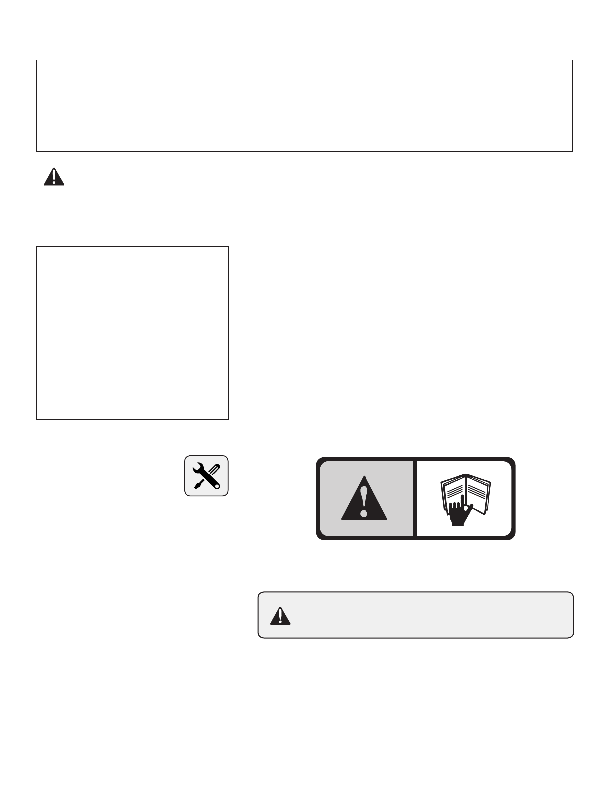
This symbol will help to point out important safety precautions
throughout this manual. It means: ATTENTION! BECOME
ALERT! Your safety is involved.
The safety labels shown in this section are placed in important areas on your product
to draw attention to potential safety hazards.
On your product safety labels, the words DANGER, WARNING and CAUTION are
used with the safety-alert symbol. DANGER identies the most serious hazards.
The operator’s manual also explains any potential safety hazards whenever necessary
in special safety messages that are identied with the word, CAUTION, and the safety-
alert symbol.
CUSTOMER RESPONSIBILITIES
- Please read & retain this manual. The instructions will enable to assemble and maintain your product properly.
- Please carefully read and observe the SAFETY SECTION of this manual.
- Follow a regular schedule in maintaining and caring for your Brinly-Hardy product.
CONGRATULATIONS on the purchase of your new Brinly-Hardy Roger 180º Dump Kit! This accessory has been designed,
engineered and manufactured to give you the best possible dependability and performance.
Should you experience any problem you cannot easily remedy, please do not hesitate to contact our knowledgeable customer
service department toll-free at 1-877-728-8224. We have competent, well trained technicians to help you with the assembly and
use of your product.
TABLE OF CONTENTS
=======================
INTRODUCTION ...............2
SAFETY .....................2
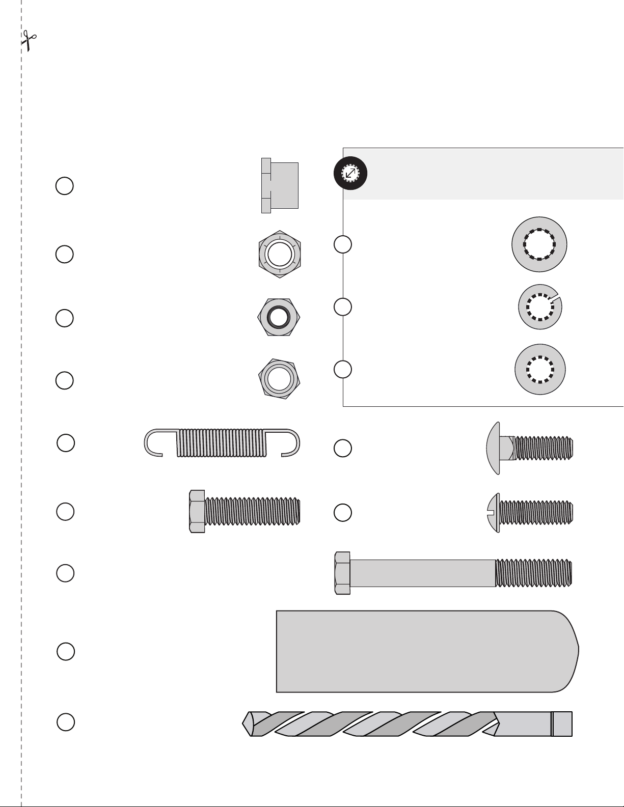
HARDWARE IDENTIFIER ......3
PART LIST . . . . . . . . . . . . . . . . . . 4
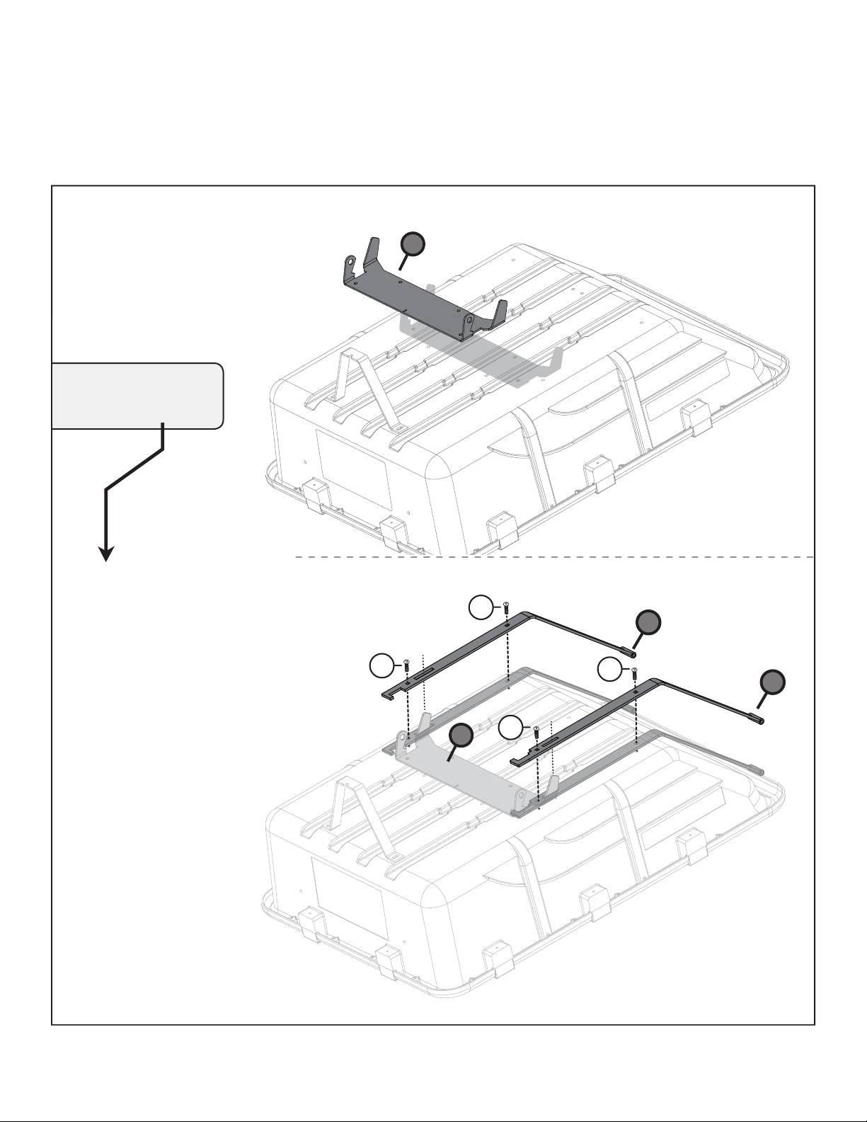
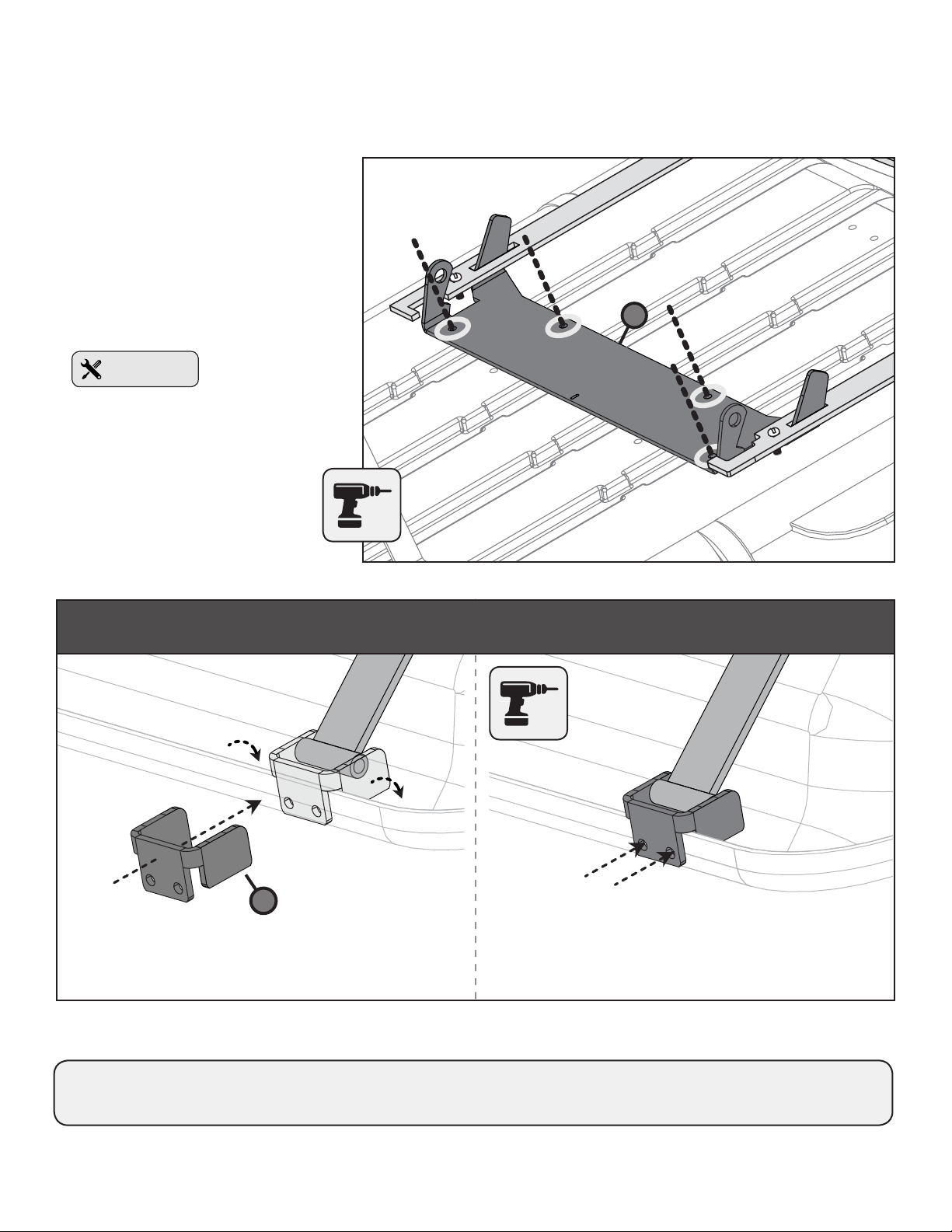
ASSEMBLY ............... 5 - 15
OPERATION ............. 16 - 17
WARRANTY .................18
RECORD PURCHASE INFORMATION
===========================================
Record your purchase information in the spaces provided below:
DATE OF
PURCHASE _________________________________________________
COMPANY NAME ____________________________________________
SERIAL NUMBER ____________________________________________
CO. PHONE ________________________________________________
REQUIRED TOOLS
FOR ASSEMBLY
==========================
• 1/2” Wrench
• 9/16” Wrench & Ratchet
• Flathead Screwdriver
• Drill (5/16" Bit included with kit)
• Gloves

3English Manual 1018671-B
================================================================================================
HARDWARE IDENTIFIER
TEAR OUT THIS PAGE
Illustrations on this page are to-scale for identication of hardware during assembly. Tear out this page for quick reference.
Simply lay the hardware directly on top of the illustrations below to verify you’re using the correct parts.
10
Bushing: Hex Head
3/8” x 1/2" (x2). . . . . . . . . . . . . . .
1001301
Exterior circumferences of the washers can
vary. These dimensions are a measurement of
the internal diameter of the washer.
14
Washer: Flat
3/8” (x2) . . . . . . . . . . . . . . .
45M1313P
15
Washer: Lock
5/16” (x14) . . . . . . . . . . . . . . .
40M1000P
16
Washer: Flat
5/16” (x8) . . . . . . . . . . . . . . . .
45M1111P
12
Nut: Nylon Lock
5/16” (x2) . . . . . . . . . . . . . . . . . . .
B-4786
13
Nut: Hex Head
5/16” (x14) . . . . . . . . . . . . . . . . . .
30M1000P
Bolt: Carriage
5/16 x 1” (x8) . . . . . . .
11M1016P
18
Screw:
Round Head
5/16 x 1” (x8) . . . . . . .
20M1020P
20
Bolt: Hex Head
3/8 x 1 1/4”
(x2) . . . . . . . . . . . . .
2M1220P
19
17
Spring
(x1) . . . .
B-6300
11
Nut: Nylon Lock
3/8” (x4) . . . . . . . . . . . . . . . . . . .
B-4820
Bolt: Hex Head 3/8 x 3” (x2) . . . . . . . . . . . . . . .
2M1248P
21
Grip: Flat
( for Handle )
(x1) . . . . . . . . . . . . . . . . . . . . . . . . . .
R-1882
22
Drill Bit (x1) . . . . . . . . . . . . .
1018992
23

4English Manual 1018671-B
REQUIRED TOOLS
FOR ASSEMBLY
- - - - - - - - - - - - - - - - - - - - - - -
• 1/2” Wrench
• 9/16” Wrench & Ratchet
• Flathead Screwdriver
• Drill (5/16" Bit included with kit)
• Gloves
PARTS
1Rocker Base Plate 1018681 1
2Pivot Arm; Left 1018698 1
3Pivot Arm; Right 1018697 1
4Drilling Template; Pivot Arms 1018696 1
5Pivot Bracket; Rear 1018684 2
6A-Frame Support Bracket 1018687 1
7Rocker Motion Bracket 1018682 1
8Rocker Handle 1018881 1
9Label;* "1. Release" 1018836 1
Hardware Bag ( 1018946 )
10 Bushing, 3/8" x 1/2" 1001301 2
11 Nut; Nylon Lock, 3/8” B-4820 4
12 Nut; Nylon Lock, 5/16” B-4786 2
13 Nut; Hex Head, 5/16” 30M1000P 14
14 Washer; Flat, 3/8” 45M1313P 2
15 Washer; Lock, 5/16” 40M1000P 14
16 Washer; Flat, 5/16" 45M1111P 8
17 Spring B-6300 1
18 Bolt; Carriage, 5/16” x 1” 11M1016P 8
19 Bolt; Hex Head, 3/8” x 1 1/4” 2M1220P 2
20 Screw; Round Head, 5/16” x 1" 20M1020P 8
21 Bolt; Hex Head, 3/8” x 3” 2M1248P 2
22 Grip, Flat R-1882 1
23 Drill Bit 1018992 1
REF DESCRIPTION Part# QTY
Call, Toll-Free: 877-728-8224
Chat online: www.brinly.com
Email: customerservice@brinly.com
If you have any installation questions, are missing parts
or need replacement parts, don’t go back to the store!
Please contact our Customer Service department:
1
8
7
2
4 6
3
5
*not illustrated
180º ROGER KIT for 10P CARTS
For: PCT-100BH, PCT-101BH and PCT-100JD

5English Manual 1018671-B
================================================================================================
ASSEMBLY
STEP 2
------------------------------
REMOVING A-FRAME
Remove the hardware connecting
your current cart bed to the A-frame.
NOTE: Hardware
necessary to be removed
is illustrated here. ( A total
of 8 nuts, 8 bolts and 8
washers).
STEP 1
------------------------------
Tear out the Hardware Identier
(page 3) for a faster assembly time.
Illustrations on this page are
to-scale for identication of the
hardware during assembly.
Simply lay the hardware
directly on top of the illustrations
to verify you’re assembling with
the correct parts.
15
15
15
15
3
English Manual 1018671-A
================================================================================================
HARDWARE IDENTIFIER
TEAR OUT THIS PAGE
Illustrations on this page are to-scale for identication of hardware during assembly. Tear out this page for quick reference.
Simply lay the hardware directly on top of the illustrations below to verify you’re using the correct parts.
10
Bushing: Hex Head
3/8” x 1/2" (x2). . . . . . . . . . . . . . .
1001301
Exterior circumferences of the washers can
vary. These dimensions are a measurement of
the internal diameter of the washer.
14
Washer: Flat
3/8” (x2) . . . . . . . . . . . . . . .
45M1313P
15
Washer: Lock
5/16 ” (x14) . . . . . . . . . . . . . . .
40M1000P
16
Washer: Flat
5/16” (x8) . . . . . . . . . . . . . . . .
45 M1111P
12
Nut: Nylon Lock
5/16” (x2) . . . . . . . . . . . . . . . . . . .
B- 4786
13
Nut: Hex Head
5/16 ” (x14) . . . . . . . . . . . . . . . . . .
30M1000P
Bolt: Carriage
5/16 x 1” (x8) . . . . . . .
11M1 016 P
18
Screw:
Round Head
5/16 x 1” (x8) . . . . . . .
20M1020P
20
Bolt: Hex Head
3/8 x 1 1/4”
(x2) . . . . . . . . . . . . .
2M12 20 P
19
17
Spring
(x1) . . . .
B-6300
11
Nut: Nylon Lock
3/8” (x4) . . . . . . . . . . . . . . . . . . .
B-4820
Bolt: Hex Head 3/8 x 3” (x2) . . . . . . . . . . . . . . .
2M12 48 P
21
Grip: Flat
( for Handle )
(x1) . . . . . . . . . . . . . . . . . . . . . . . . . .
R-188 2
22
Drill Bit (x1) . . . . . . . . . . . . .
1018992
23
BRINLY.COM
An assembly video and
additional info for this kit is
available on our website.
Please visit the URL above
OR
scan
this QR
code:

6English Manual 1018671-B
================================================================================================
NOTE:
Alignment of this part
HAPPENS HERE
ASSEMBLY
STEP 3-A
------------------------------------------------------------------------------
Find this hardware:
- x4 Round Head Screws (20)
5/16” x 1"
Place the rocker Base
Plate (1) against the bed of
the cart.
For alignment and drilling
purposes, temporarily add the
pivot arms (2and 3) as illustrated.
Using four of the existing cart
holes, slide four 5/16" x 1" Round
Head Screws (20) in place.
Note: No need to tighten with a
nut, you will remove the pivot
arms after this step.
15
15
1
3
2
1
20
20 20
20

7English Manual 1018671-B
================================================================================================
ASSEMBLY
STEP 3-B (Drilling)
------------------------------
Find the provided Drill Bit (23).
Using the remaining
circular holes of the rocker
plate (1) as a template, drill four
holes through the cart.
Remove and set aside the four Round Head Screws (20) added on Step 3-A,
the Drilling Template (4) as well as the Pivot Arms (2 & 3).
1
Drill Bit (23)
4
15
15
Drill through the template holes, straight into the bed of
the cart. Repeat this step with the other pivot arm.
Slide the drilling template (4) in place as illustrated and
center it over the end of the pivot arm.
On the other end of the pivot arms (where the cart rim and pivot arms meet)
you'll need to drill four holes that will connect the pivot arms to the bed of the cart.
STEP 3-C (Drilling)

8English Manual 1018671-B
================================================================================================
NOTE: Hooks of the Pivot Arms will
face toward center of the cart.
Repeat this step for the other pivot bracket.
ASSEMBLY
STEP 4
--------------------------------
Find this hardware:
- x4 Screws; Round Head (20) - 5/16” x 1"
- x4 Washer; Flat (16) - 5/16”
- x4 Washer; Lock (15) - 5/16”
- x4 Nut; Hex Head (13) - 5/16”
Add a Flat Washer (16) to each Round Head
Screw (20). Align the Pivot Bracket (5) as
illustrated to the right.
Secure the Pivot brackets (5) underneath in
place by adding a Lock Washer (15) and Nut
(13) to the end of the screw.
STEP 5-A
--------------------------------
Find this hardware:
- x2 Bolt; Carriage (18) - 5/16” x 1"
- x2 Washer; Lock (15) - 5/16"
- x2 Nut; Hex Head (13) - 5/16"
Align holes of the Right Pivot Arm (3)
with the A-frame.
Add both carriage bolts (18) to the Pivot Arm (3)
and A-Frame as illustrated here.
3
18
18
15
13
20
16
15
13
20
16
5

9English Manual 1018671-B
================================================================================================
NOTE: Hooks of the Pivot Arms will
face toward center of the cart.
DO NOT tighten
the nuts (13) fully YET.
DO NOT tighten
the nuts (13) fully YET.
Beneath the cart A-frame, start to add
two 5/16" lock washers (15) and 5/16"
nuts (13) on the outside edges of the
tray and plates.
13
15
13
15
ASSEMBLY
STEP 5-B
-------------------------------
Find this hardware:
- x2 Bolt; Carriage (18) - 5/16” x 1"
- x2 Washer; Lock (15) - 5/16"
- x2 Nut; Hex Head (13) - 5/16"
Align holes of the Left Pivot Arm (2)
with the A-frame.
Add both carriage bolts (18) to the Pivot Arm (2)
and A-Frame as illustrated here.
Beneath the cart A-frame, start to add two 5/16"
lock washers (15) and 5/16" nuts (13) on the
outside edges of the tray and plates.
2
13
13
18
15
15
18
18
15
13
STEP 5-A (Continued)
-------------------------------

10English Manual 1018671-B
================================================================================================
ASSEMBLY
Find this hardware:
- x2 Bolt; Carriage (18) - 5/16” x 1"
- x2 Washer; Lock (15) - 5/16"
- x2 Nut; Hex Head (13) - 5/16"
Align the A-frame support bracket (6) from
above the axle and run each bolt through.
Add a lock washer (15) to both bolts (18)
and secure fully under the A-frame with two
Nuts (13).
STEP 5-D
-----------------------------------
6
15 15
13
18
Aligning the Pivot Arms
Temporarily slide the rocker
base (1) into the slots of the
pivot arms (2) and (3).
See Illustration.
STEP 5-C
-----------------------------------
x4
1
2
3
Tighten the four 5/16" nuts
(18) from Steps 5-A and 5-B
(reference pages 8-9).
Remove the rocker base (1) from the
assembly (this will be used on step 6,
page 11).

11English Manual 1018671-B
================================================================================================
STEP 6
------------------------------------------------------------------------------
ASSEMBLY
Find this hardware:
- x4 Screw; Round Head (20) - 5/16” x 1"
- x4 Washer; Flat (16) - 5/16”
- x4 Washer; Lock (15) - 5/16”
- x4 Nut; Hex Head (13) - 5/16”
For Ease of Assembly:
Align the new drilled cart holes and rocker plate.
Attach the rocker base plate (1) to the cart bed as
illustrated here using the hardware listed.
Stand the cart bed upright and lean it aginst the lock bracket as illustrated.
1
13
15
20
16
20
16
16
20
16
20
15
13
15
13
15
13
20
161513
Bed of
the Cart
Rocker
Base Plate
1
NOTE: Heads
of the screw should
start from inside
the cart.
x4

12English Manual 1018671-B
================================================================================================
ASSEMBLY
17
1
17 7
7
1
Lift the motion bracket (7) up and over
the rst set of extended arms of the
base plate (1).
Align the two rocker parts:
- x1 Base Plate (1)
- x1 Motion Bracket (7)
Slide two bushings (10) in
place as illustrated.
STEP 8-A
-----------------------------------
10
10
7
1
STEP 7
------------------------------------------------------------------------------
1. Lay the cart bed down.
2. Hook one end of the spring (17) through the hole of
the Rocker Motion Bracket (7) as illustrated here.
3. Expanding the spring (17), pull to hook
the other end through the small
center hole along the edge of the
Base Plate Rocker (1).

13English Manual 1018671-B
================================================================================================
ASSEMBLY
STEP 9
------------------------------------------------------------------------------
Find this hardware:
- x2 Bolt; Carriage (18) - 5/16" x 1"
- x2 Nut; Nylon Lock (12) - 5/16"
Align the Rocker
Handle (8) with the
square holes of the
Rocker Motion Bracket
(7) as illustrated here.
Add both Bolts (18) from beneath the
Rocker Motion Bracket (7), through
the handle (8) and secure in place
with a Nylon Lock Nut (12).
Finally, slide the
grip (22) over the end
of the handle (8).
8
12
22
12
18
18
7
Label is on the
other side of the
handle, facing up
after the cart is
ipped over.
STEP 8-B
------------------------
19
19
14
14
11
11
Find this hardware:
- x2 Bolt; Hex Head (19)
3/8" x 1 1/4"
- x2 Washer; Flat (14) - 3/8"
- x2 Nut; Nylon lock,
3/8” (11) - 3/8"
Add a washer (14) to each bolt (19).
As illustrated here, run these bolts
through the bushings that were
added on step 8-A.
Be sure to allow movement,
however, loosely secure in
place with two Hex Head Locking
Nuts (11).

14English Manual 1018671-B
================================================================================================
DON'T OVERTIGHTEN
Allow movement.
ASSEMBLY
15
15
15
15
Find this hardware:
- x2 Bolts (21) - 3/8” x 3"
- x2 Nuts; Nylon Lock, 3/8" (11)
Secure both Pivot Arms to the Pivot
Brackets (17) with a Bolt (21) and
Nylon lock nut (11).
Repeat this step for the
other pivot arm.
Lower the pivot arms
in place, resting within the
pivot brackets (5) that were
installed on step 4 (pg 8).
STEP 10
------------------------------------------------------------------------------
Align the bed of the cart with the rest of
the assembly as illustrated here.
21
11
5

15English Manual 1018671-B
================================================================================================
Rotate the cart bed to its'
transport position by lifting it
slowly back toward the A-Frame
and tow bar.
Make sure the lock bracket clicks
in place with the foot pedal for
alignment.
ASSEMBLY
STEP 12
-------------------------------
Peel the paper backing off of
the "1. RELEASE" label (9) and place it
on the tow bar as illustrated here.
9
STEP 11
-------------------------------
------------------------------------------------------------------------------
ASSEMBLY IS COMPLETE!

16English Manual 1018671-B
================================================================================================
OPERATION
CAUTION:
Avoid injury!
• Before dumping cart, park machine safely.
• Before backing up, make sure the area is clear of bystanders, especially children.
• Make sure cart is installed to the towing machine.
• Keep hands, feet and other body parts away from unloading areas and locking points
to prevent injury from hauled materials or the cart itself.
STEP 1
-----------------------------------
Press down on the foot
pedal to release the lock and
rotate cart to the standard
unloading position.
STEP 2
-----------------------------------
Pull the lever and continue
to guide the range of motion,
ipping the bed of the cart
toward an 180º unload.

17English Manual 1018671-B
================================================================================================
OPERATION
Brinly-Hardy Company • 3230 Industrial Parkway • Jeffersonville, IN 47130 • (877) 728-8224
INSTALLATION QUESTIONS? MISSING PARTS? NEED REPLACEMENT PARTS?
DON’T GO BACK TO THE STORE!
Please call Customer Service Department Toll Free 877-728-8224 OR Email: customerservice@brinly.com
-----------------------------------------------------------------------
STEP 3
-----------------------------------
After unloading the cart, be
sure to return it to the normal
transport position and lock
securely in place.

18English Manual 1018671-B
The limited warranty set forth below is given by Brinly-Hardy
Company with respect to new merchandise purchased and
used in the United States, its possessions and territories.
Brinly-Hardy Company warrants the products listed below
against defects in material and workmanship, and will at its
option, repair or replace, free of charge, any part found to be
defective in materials or workmanship. This limited warranty shall
only apply if this product has been assembled, operated, and
maintained in accordance with the Operator’s manual furnished
with the product, and has not been subject to misuse, abuse,
commercial use, neglect, accident, improper maintenance,
alteration, vandalism, theft, fire, water, or damage because of
other peril or natural disaster.
Parts found to be defective within the warranty period will be
replaced at our expense. Our obligation under this warranty is
expressly limited to the replacement or repair, at our option, of
parts found to be defective in material and workmanship.
HOW TO OBTAIN SERVICE: Warranty parts replacements
are available, ONLY WITH PROOF OF PURCHASE, through
our Customer Service Department. Call 877-728-8224.
This limited warranty does not provide coverage in the following
cases:
a) Routine maintenance items such as lubricants and
filters.
b) Normal deterioration of the exterior finish due to
use or exposure.
c) Transportation and/or labor charges.
d) The warranty does not include commercial and/or
rental use.
No implied warranty, including any implied warranty of
merchantability of fitness for a particular purpose, applies
after the applicable period of express written warranty
above as to the part as identified below. No other express
warranty whether written or oral, except as mentioned
above, given by any person or entity, including a dealer
or retailer, with respect to any product, shall bind Brinly-
Hardy Co. During the period of the warranty, the exclusive
remedy is repair or replacement of the product as set forth
above.
The provisions as set forth in this warranty provide the sole
and exclusive remedy arising from the sale. Brinly-Hardy
Co. shall not be liable for incidental or consequential loss
or damage including, without limitation, expenses incurred
for substitute or replacement lawn care services or for
rental expenses to temporarily replace a warranted product.
Some states do not allow the exclusion or limitation of incidental
or consequential damages, or limitations on how long an implied
warranty lasts, so the above exclusions or limitations may not
apply to you.
During the warranty period, the exclusive remedy is replacement
of the part. In no event shall recovery of any kind be greater that
the amount of the purchase price of the product sold. Alteration
of safety features of the product shall void this warranty. You
assume the risk and liability for loss, damage, or injury to you
and your property and/or to others and their property arising out
of the misuse or inability to use this product.
This limited warranty shall not extend to anyone other than the
original purchaser or to the person for whom it was purchased
as a gift.
HOW STATE LAW RELATES TO THIS WARRANTY:
This limited warranty gives you specific legal rights, and you
may also have other rights which vary from state to state.
IMPORTANT:
The Warranty period stated below begins with the PROOF
OF PURCHASE. Without the proof of purchase, the Warranty
period begins from the date of manufacture determined by the
serial number manufacturing date.
WARRANTY PERIOD:
The warranty period for the parts included in this kit are as
follows: Steel Frame Parts: consumer - 2 Years, commercial -
90 days.
MANUFACTURER’S LIMITED WARRANTY FOR
BRINLY PULL-BEHIND ACCESSORIES
Brinly-Hardy Company • 3230 Industrial Parkway • Jeffersonville, IN 47130 • (877) 728-8224 • brinly.com
Table of contents
Other Brinly Outdoor Cart manuals