Tower Electronic Systems MAXI-T User manual

OCTOBER 2002 MAXI-T MANUAL
OPERATING MANUAL
MAXI-T
SINGLE PHASE INPUT / OUTPUT
ON-LINE UPS
1

OCTOBER 2002 MAXI-T MANUAL
CONTENTS
INTRODUCTION
General Description
Location
INSTALLATION
General
Input an Output cabling an circuit breaker ata
Battery Details
Battery Configuration
Battery Connection
SYSTEM OPERATING PROCEDURES
Initial Start-up
Transfer of Loa to Reserve
TROUBLE SHOOTING
Description of alarms
TECHNICAL SPECIFICATIONS
DC Data
Battery
Dimensions an weights of UPS cabinet
UPS SERVICE HISTORY
2

OCTOBER 2002 MAXI-T MANUAL
INTRODUCTION
GENERAL DESCRIPTION
The Maxi-T range of UPS units utilises a mo ern innovative esign provi ing many benefits
to the user.
A battery is kept charge via the switching circuit an in the event of a mains failure, the
battery takes over supplying power to the inverter.
The result is that the UPS supplies an uninterrupte , regulate an controlle supply to the
connecte loa un er all con itions inclu ing mains failure, loa steps an at minimum
battery levels.
To provi e a itional security to the connecte loa , a static bypass switch will transfer the
loa to the mains supply un er overloa or fault con ition.
The units are house in a compact aesthetically pleasing cabinet, which inclu es a user-
frien ly igital front panel.
LOCATION
The following shoul be consi ere when planning the location of your UPS.
1. Protect against excessive temperature an humi ity
2. Protection against elements – especially moisture.
3. Ease of access.
4. Ease of electrical reticulation.
5. A equate ventilation clearance.
6. Close proximity to the UPS battery.
3
OCTOBER 2002 MAXI-T MANUAL
INSTALLATION
GENERAL
The following information will be of assistance when installing your UPS. Care shoul be
taken to select the correct circuit breakers an cable sizes. Information is provi e in TABLE
1 that will assist with the selection.
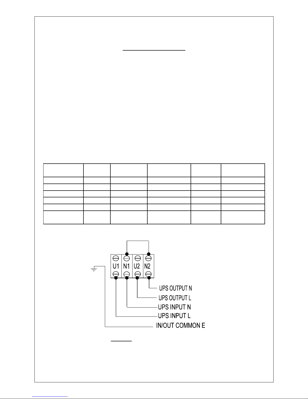
INPUT AND OUTPUT CABLING AND CIRCUIT BREAKER DATA
The recommen e input circuit breaker (in clients’ DB boar ) an cable sizes for the ifferent
UPS units are as follows:
NOTE:•The input circuit breaker must have a D curve rating.
•All cable sizes are rate for a maximum istance of up to 50 meters.
UPS RATING INPUT
AMPS
RECOM I/P
ACB
INPUT CABLE OUTPUT
AMPS
OUTPUT
CABLE
3kVA 13(1ph) 20A 1 pole 4mm2 2c+e 13A 4mm2 2c+e
5kVA 22(1ph) 30A 1 pole 6mm2 2c+e 22A 4mm2 2c+e
8kVA 35(1ph) 40A 1 pole 10mm2 2c+e 35A 6mm2 2c+e
10kVA 44(1ph) 50A 1plole 10mm2 2c+e 44A 10mm2 2c+e
15kVA 67(1ph) 80A 1 pole 16mm2 2c+e 65A 16mm2 2c+e
20kVA 87(1ph) 100A 1
pole
20mm2 2c+e 87A 20mm2 2c+e
.
Figure 1: Installation wiring layout.
4

OCTOBER 2002 MAXI-T MANUAL
BATTERY DETAILS
Please take special care when installing the batteries an note the following:
•Batteries shoul only be installe by a qualifie technician.
•Take special care when installing the battery trays
•Do not short out the battery terminals.
•Do not rop the batteries.
•Ensure that the polarity connections are correct.
•Ensure that the battery interconnections are securely fastene .
•DC is angerous an can be lethal
•Battery life is consi erably shortene when operate at temperatures above 25ºC.
•Keep batteries away from irect sunlight an keep the room as cool as possible.
The ollowing battery cables and accessories are supplied with your unit:
•Short inter-battery connectors
•Me ium en connector cables
•Long cables for connection to DC terminals F1, F2, F3.
BATTERY CONFIGURATION
A battery tray can house 16 batteries. [32 batteries per bank.]
The UPS cabinet can house a total of 2 or 4 battery trays. [32 or 64 batteries in total.]
An optional external battery cabinet can house an a itional 6 trays. [96 batteries extra.]
BATTERY CONNECTION
Open all three battery fuses.
Populate the battery trays, each with 16 x 12V x 7A/h batteries - terminals facing out - see
figure 2.
Connect the short interconnecting cables to all the batteries on the LHS an RHS.
Connect the long re an black cables at the front of the tray but do not connect the longer
link at the back of the tray.
Insert trays into the UPS, starting at the bottom - taking care not to pinch any of the cables
that must go through their respective holes (in the front).
5

OCTOBER 2002 MAXI-T MANUAL
BATTERY CONNECTION (cont…)
Connect the lower shelf's black cable (negative) to bottom of F2 an the upper shelf's re
cable (positive) to the bottom of F1 (as shown in figure 2).
Connect the remaining long re an black cables to either si e of F3.
Slightly open each battery tray an measure the ifferential between the last two battery
terminals (closest to the back of the unit).
If this ifferential voltage is less than 3VDC, it is safe to insert the me ium en connector
cables across those links that were just measure .
Take care when re-closing the trays that these me ium connecting cables are tucke un er
the above tray to avoi them being pinche .
Figure 2: Single battery bank connection diagram.
A secon set of 32 batteries (2 trays) can be installe if require .
Install the secon battery bank following the proce ures outline for the first battery bank.
The positive an negative of each tray will be connecte in parallel to the respective tray of
the first bank.
The installation of the batteries in the external battery cabinet is i entical to the proce ure
escribe above.
The batteries house in the external battery cabinet are also connecte to terminals F1, F2 &
F3 in this cabinet an must be connecte to terminals F1 & F2 in the UPS cabinet.
6

OCTOBER 2002 MAXI-T MANUAL
SYSTEM OPERATING PROCEDURES
INITIAL START-UP OF UPS UNIT
•Turn the INVERTER EY SWITCH to the off position.
•For 3 - 5kVA units
•Place the ROTARY BYPASS switch into the TEST position.
•For 8 - 20kVA units
•Close the BYPASS ISOLATOR (SW2).
•Open the OUTPUT ISOLATOR (SW1).
•Close the AC input circuit breaker (CB1).
•The LCD will activate.
•After a perio of approximately 30 secon s the analogue values an status alarms will be
isplaye .
•The unit will synchronise to input reserve source.
•Depress ALARM CANCEL button to silence alarm.
•Turn the INVERTER EY SWITCH to the “ON” position.
•The unit will start up when synchronise to mains (reserve source).
•The UPS output voltage will ramp up to 230VAC.
•Ensure that *NO ACTIVE ALARMS* is isplaye in the alarm status block an that the
battery voltage is greater than 360VDC (432VDC is the charging value).
•Measure the DC ifferential voltage across F1 an close this fuse if the voltage is less
than 30VDC.
•Repeat for F2 an F3.
•Turn the INVERTER EY SWITCH to the “OFF” position an confirm LOAD ON BYPASS
is isplaye on the LCD DISPLAY.
•For 3 - 5kVA units
•Place the ROTARY BYPASS switch into the NORMAL position.
•For 8 - 20kVA units
•Close the OUTPUT ISOLATOR (SW1).
•Open the BYPASS ISOLATOR (SW2).
•Turn the INVERTER EY SWITCH to the “ON” position (CW) an epress ALARM
CANCEL button to silence alarm.
•Confirm *NO ACTIVE ALARMS* is isplaye on the LCD DISPLAY within 60 sec.
•The unit is operating normally.
7

OCTOBER 2002 MAXI-T MANUAL
TRANSFER LOAD TO RESERVE
•To transfer to bypass without loosing the loa , ensure that *NO ACTIVE ALARMS* is
isplaye .
•Turn the INVERTER KEY SWITCH to the off position.
•For 3 - 5kVA units
•Place the ROTARY BYPASS switch into the TEST position.
•For 8 - 20kVA units
•Close the BYPASS ISOLATOR (SW2).
•Open the OUTPUT ISOLATOR (SW1).
•The loa is being supplie via the etour supply.
•Open DC Input fuses (F1, F2 an F3).
•Open AC input circuit breaker (CB1).
•Wait 1 min for the internal capacitors to ischarge (Electronics will ie when ischarge .)
•To switch the unit on again, refer to INITIAL START-UP.
TROUBLE SHOOTING
The Maxi-T range is esigne to provi e the maximum reliability possible. Provi e the
equipment is operate within the esign specifications an is installe in the correct
environment the high-anticipate reliability will be obtaine .
In the unlikely event of a failure occurring, it is a visable to seek a vice from your local
service centre. This will prevent any further amage to the UPS an also prevent any
unnecessary expense.
Shoul any of the system circuit breakers trip, it is a visable to investigate the problem
before attempting to close the breakers, otherwise further amage coul occur.
The following alarms are consi ere to be the type that will occur repetitively:
RES VOLTS OUT OF LIMITS
LOSS OF PHASE LOCK
LOW DC SHUTDOWN
INVERTER OVERLOAD
For etaile escriptions see “DESCRIPTION OF ALARMS”.
If any other alarms persist, contact your local service center imme iately.
8

OCTOBER 2002 MAXI-T MANUAL
DESCRIPTION OF ALARMS
ALARM EXPLANATION
HIGH DC SHUTDOWN Input c voltage excee e trip point (+20% of
nominal battery voltage). The over-voltage
must be active for longer than 15 secon s.
BATTERY DISCHARGING DC voltage has roppe below nominal
battery voltage, in icating that energy is
being raine from the battery an not from
the rectifier.
DC CRITICAL DC voltage has roppe to a value close to
the inverter switch-off level.
LOW DC SHUTDOWN DC voltage has roppe below the low c trip
point (-20% of nominal battery voltage).
INVERTER IN STANDBY The inverter is off. The inverter can restart
automatically when the con ition that
switche it off e.g. LOW DC SHUTDOWN
returns too normal.
INV VOLTS OUT LIMITS The inverter output voltage is out of
tolerance. (+10% or –10%).
INVERTER OVERLOADED The loa connecte to the output of the
inverter excee e 120% of its full rating. This
con ition was active for longer than 15
secon s.
OVER-CURRENT STOP The inverter has switche off ue to
excessive overloa (output current excee e
300% for longer than 40ms).
INVERTER LOCKOUT The inverter has faile to start after 5 times
attempts within 250 secon s an has
switche off. The loa will now be supplie
from the mains via the Static Switch.
9

OCTOBER 2002 MAXI-T MANUAL
DESCRIPTION OF ALARMS (cont…)
RES V OUT OF LIMITS The reserve source voltage is out of
tolerance. (+/-15%).
LOAD ON BYPASS The Critical Loa is fe from the reserve
source via the static switch.
ON/OFF SWITCH OFF The key switch on the front oor is in the OFF
position.
FREQ OUT LIMITS The reserve source frequency is out of
tolerance. (+/-2%)
LOSS OF PHASE LOCK The inverter is unable to phase lock to its
reserve source.
SINE ERROR The instantaneous value of the inverter
output voltage eviate by more than 15%.
The internal voltage etector has etecte
this malfunction. Loa will be switche to the
reserve source if it is available.
CHARGER FAIL The Rectifier/Charger is off.
OVER-TEMPERATURE The internal temperature of the unit is
excessive.
NO ACTIVE ALARMS No alarm con itions exist the unit is operating
normally.
SUPERVISION STOP The inverter has stoppe operating ue to an
over-current con ition etecte in the IGBT
Bri ge. This coul be ue to either an
external fault e.g. a short circuit or an internal
fault. The inverter will not restart.
10

OCTOBER 2002 MAXI-T MANUAL
TECHNICAL SPECIFICATIONS
UPS INPUT
Input rate voltage 230V, 1 Phase +/-15%
Input frequency 50Hz, +/- 5%
Input power factor >0,9 IND
UPS OUTPUT
Rate output at 0,7 IND PF 3kVA, 5kVA, 8kVA, 10kVA, 15kVA, 20kVA
Rate output voltage 230V, 1Phase
Stea y State output voltage regulation +/- 1%
from no-loa to full loa at rate PF
an DC voltage variation from
maximum to minimum
Transient voltage regulation with +/- 5%
100% application or removal of loa
Recovery Time 30 Millisecon s
Overloa Capability 200% for 15 secon s
Crest Factor Ratio 3 : 1
Total Harmonic Distortion Less than 5% (typically 3% for linear loa s)
Loa Power Factor From 0,6 in uctive to unity within kW rating
Waveform Sinusoi al
Frequency:
Free Running 50Hz +/- 0,05%
Synchronise with mains 50Hz +/- 2% (a justable)
GENERAL
Efficiency at full loa Input - Output 95%
Au ible noise Less than 50 DBA at 1 metre
Static Transfer Switch 1000% Overloa 5 cycles
Operating Temperature Range at 0 egrees C to 40 egrees C
maximum humi ity of 90%
Lightning protection esigne to withstan stan ar test impulses of 6KV
an 3KA
11

OCTOBER 2002 MAXI-T MANUAL
BATTERY
Type Lea aci maintenance free
Anticipate life 3 to 5 years epen ing on number of ischarges
an temperature
DIMENSIONS AND WEIGHTS OF UPS CABINET
Rating 3kVA, 5kVA 8kVA, 10kVA, 15kVA, an 20kVA.
UPS cabinet, with stan ar battery (mm) (SHORT) 370 (W) x 650 (D) x 550 (H)
UPS cabinet, with stan ar battery (mm) (TALL) 370 (W) x 650 (D) x 850 (H)
Weights of UPS with one set batteries 120kg 150kg 165kg 180kg 215kg 230kg
DIMENSIONS AND WEIGHTS OF OPTIONAL BATTERY CABINET
Exten e battery cabinet 370 (W) x 650 (D) x 850 (H)
Weight of battery cabinet with 3 sets batteries 300 kg
12

OCTOBER 2002 MAXI-T MANUAL
DC DATA
5kVA 32 X 12 VOLT BATTERIES: 192 CELLS
V Float 432V
V Min 336V
Max DC ischarge current 11.0A
Max DC Power 3.7kW
Maximum charging 1.4A
8kVA 32 X 12 VOLT BATTERIES: 192 CELLS
V Float 432V
V Min 336V
Max DC ischarge current 17.5A
Max DC Power 5.9kW
Maximum charging 2.0A
10kVA 32 X 12 VOLT BATTERIES: 192 CELLS
V Float 432V
V Min 336V
Max DC ischarge current 21.9A
Max DC Power 7.4kW
Maximum charging 3.0A
15kVA 32 X 12 VOLT BATTERIES: 192 CELLS
V Float 432V
V Min 336V
Max DC ischarge current 32.9A
Max DC Power 11.0kW
Maximum charging 5.0A
20kVA 32 X 12 VOLT BATTERIES: 192 CELLS
V Float 432V
V Min 336V
Max DC ischarge current 32.9A
Max DC Power 14.8kW
Maximum charging 5.0A
13

OCTOBER 2002 MAXI-T MANUAL
UPS SERVICE HISTORY
INSTALLATION DATE
INSTALLED BY
COMMISSIONED DATE
COMMISSIONED BY
SERVICE DATE SERVICED BY RECOMMENDED NEXT
SERVICE
14
Table of contents
Popular UPS manuals by other brands


Eaton
Eaton 9125 Two-in-One UPS 2500 user guide

Vertiv
Vertiv Liebert ITA2-08KRT208 user manual

Marathon Power
Marathon Power vault series user manual

Bay Networks
Bay Networks BayStack UPS45 Quick reference guide

PowerWalker
PowerWalker VFI 1000R LCD manual

Tripp Lite
Tripp Lite SmartPro SMART2200CRMXL Specifications


