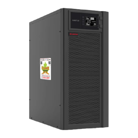
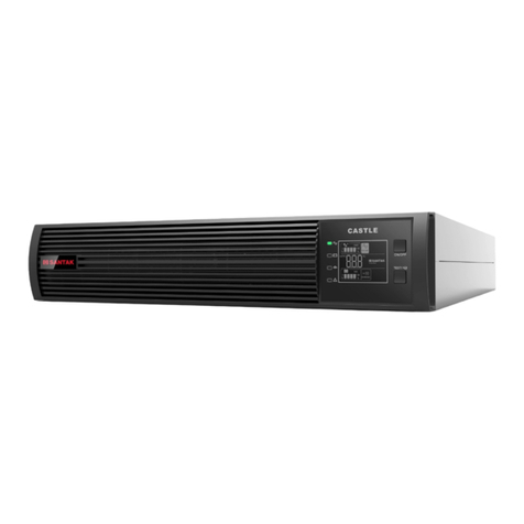
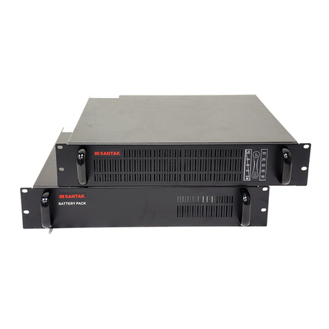
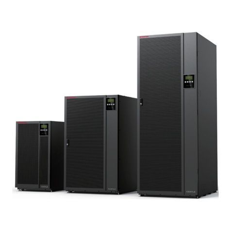
Santak CASTLE Series User manual

CASTLE Series
20K(S) -200K(S)

Thank you for choosing SANTAK products!
Please adhere to the warnings and instructions specified in the
manual and on the equipment, and keep the manual properly for
future reference. Do not try to operate the equipment before reading
all the safety information and operation instructions.
The manual applies to the 3C3 PRO series, including:
3C3 PRO 20KS
3C3 PRO 30KS
3C3 PRO 40KS
3C3 PRO 60KS
3C3 PRO 80KS
3C3 PRO 100KS
3C3 PRO 120KS
3C3 PRO 160KS
3C3 PRO 200KS

IMPORTANT NOTICE
Copyright Notice
SANTAK is committed to technological innovation as it continues to deliver better
products and services to customers. We reserve the rights to modify and update
product design, technical specifications and user manuals without further notice.
Actual products may differ from pictures shown in the manual.
The latest version of the user manual is available on www.santak.com
All Rights Reserved © 2017-2021 SANTAK Electronics (Shenzhen) Co., Ltd.

Safety Instructions
General
1. Please read through the Safety Instructions carefully before you start to operate
the equipment and keep the manual well for future reference.
2. Please pay attention to the warning symbols and follow the instructions in the
manual during operation.
3. Do not use the equipment in direct sunlight or rain, or in humid conditions.
4. Do not install the equipment near any sources of heat, such as heating devices
like electric heaters or furnaces.
5. Please make sure there is adequate space for ventilation or maintenance around
the equipment. Please follow the instructions in the manual for installation.
6. For the purpose of cleaning, please use dry and non-conductive tools to wipe
down the equipment.
7. In case of a fire, please use dry powder extinguishers. Liquid fire extinguishers are
not allowed.
8. Please make sure the floor on which the equipment is installed is strong enough to
support the weight of the equipment with battery.
9. Please make sure the total wattage requirements of the loads do not exceed the
power rating of your UPS or the capacity of the battery.
Prohibited Activities
1. Having service personnel without authorization from SANTAK to open the UPS
cabinet, which contains lethal voltages is not allowed. Unauthorized opening may
cause an unsafe condition, and will void the warranty.
2. Applying the following types of loads , the application, configuration, management
and maintenance of which may be subject to special requirements, please inquire
from dealers or SANTAK in advance:
A. High-precision industrial, scientific-research or medical instruments;
B. Facilities of which malfunctions may lead to life-threatening situations, such as
elevator;
C. Loads with large inrush current and negative power consumption;
3. Exposing batteries to fire, which may cause explosions.

Electrical Safety
1. Please make sure that the grounding is firmly connected and the wiring and
battery polarity are correctly connected.
2. Battery protection devices must be configured with a suitable over-current circuit
breaker.
3. Before you remove your UPS or reconnect the wiring, please shut down your UPS
and disconnect the air circuit breaker and the battery to ensure that the output
terminals do not carry live voltage which may cause an electric shock.
4. To ensure safety and the best performance of your UPS, please choose from
accessories recommended by SANTAK.
5. A proper four-pole over-current circuit breaker shall be installed before connecting
clients to your UPS to prevent electric shock by disconnecting all the input wiring.
Battery Safety
1. The service life of a battery is shortened as the ambient temperature rises.
Regular battery replacement ensures that your UPS work well and provides sufficient
back-up time.
2. Battery replacement and maintenance must be performed by authorized
personnel with professional knowledge in battery. Please replace an equivalent
number of batteries of the same type and model.
3. There are risks of electric shock and short circuit with the battery. Please observe
the following rules while replacing the battery to reduce the risks of electric shock:
A. Do not wear watches, rings or any other metallic objects;
B. Use insulated tools;
C. Wear rubber shoes and gloves;
D. Do not place metal tools or any other metallic accessories on the battery;
E. Disconnect the loads connected to the battery before removing terminals from the
battery.
4. Do not expose the battery to fire to avoid the risks of explosion that may result in
personal injury.
5. Non- professionals shall not open or disassemble the battery as electrolytes in the
battery contain strong acid and other dangerous substances which may cause
damage to skin and eyes. Please clean with water immediately and seek medical
assistance if the electrolytes come in contact with human skin.
6. Do not connect the battery positive and negative poles as it may cause short circuit.
Over current protection device is needed to avoid risks of burns or electric shock.

Maintenance
1. The working environment and storage method of UPS can affect its service life
and reliability. Do not use your UPS in any of the following environments where:
A. the temperature and humidity are outside the required ranges, i.e.0-40°C and 0-95%
humidity; or
B. your UPS is at high risks of vibration and collision;
C. there are metal shavings, corrosive materials, salt and flammable gases.
2. If you plan to leave your UPS idle for a long time, please store it in dry conditions
with an ambient temperature ranging between -25-55°C. Before you start up your
UPS, please keep it in an environment where the ambient temperature is at or above
0°C for 2 hours or longer.
3. Keep the air inlets and outlets clear for proper ventilation. Poor ventilation will
cause the temperature inside your UPS to rise, shortening the service life of the
components and that of your UPS.
4. The battery should be charged at least once every three months if it is left idle and
stored in an environment with a room temperature, or at least once every two months
if left idle in a high temperature environment; each charge should take more than10
hours; do not discharge with no loads connected or discharge for more than 14 hours
continuously.

Contents
Chapter 1 Introduction.........................................................................................1
1.1 Introduction.........................................................................................................1
1.2 Symbols..............................................................................................................2
Chapter 2 Appearance Description ....................................................................3
2.1 Unpacking and Inspection...................................................................................3
2.2 UPS Cabinet Dimensions ...................................................................................4
2.3 LCD Panel Instructions.....................................................................................11
Chapter 3 Installation Instructions ...................................................................12
3.1 Installation Notice .............................................................................................12
3.2 Required Clearance for Installation...................................................................12
3.3 Terminals: .........................................................................................................14
3.4 Wiring requirements and protective devices for 3C3 PRO series .....................17
3.5 Parallel Installation............................................................................................24
3.6 Steps of connecting battery cabinets to UPS....................................................27
Chapter 4 Operation...........................................................................................28
4.1 Operations of Single UPS.................................................................................28
4.2 Operations of UPS in Parallel Connection........................................................37
Chapter 5 Communications Interface...............................................................38
Chapter 6 Optional Accessories .......................................................................41
Dustproof Filter.......................................................................................................41
Chapter 7 Transportation, Maintenance and Troubleshooting.......................42
Appendix I Specifications..................................................................................44
Appendix II Reference Table of LED Indicators...............................................46
Appendix III Warranty ........................................................................................47

1
Chapter 1 Introduction
1.1 Introduction
The 3C3 PRO series are high-efficiency pure online UPS products with excellent
performance that provide double conversion, and three-phase input and output. With
perfect power source protection solutions, the 3C3 PRO effectively address multiple
power source problems such as power outage, high-voltage AC and low voltage AC,
voltage sag, damped oscillation, high voltage impulse, voltage surge, harmonic
distortion, clutter interference and frequency variation, the 3C3 PRO series is widely
applied for computers, communications devices and other controlling devices safely.
You can choose our optional accessories to enhance your UPS in order to cope with
inrush load situations in complicated industrial environment. For the governments
and a range of industries including telecommunications, financing, transportation,
manufacturing and energy, the 3C3 PRO series is the best choice of UPS.
The following functions of the 3C3 PRO series ensure high quality power for your
equipment:
●Advanced DSP digital control technology enabling improved product
performance and system reliability.
●N+X parallel redundancy (common batteries are allowed).
●Excellent protection to harsh industrial environment.
●Economic and safe ECO operation model that ensures 98% or higher USP
efficiency.
●High-resolution LCD that ensures clear and easy operation.
●Powerful communications interface and remote monitor.
●Plenty of accessories that meet a variety of needs.

2
1.2 Symbols
The following symbols may appear in the manual or other occasions. You are
suggested to understand the symbols and their meanings.
Symbols and Meanings
Symbol Meaning
DANGER
HAZARDOUS VOLTAGE
Alternating Current (AC)
Direct Current (DC)
Protective Grounding
Recycle
Keep Surroundings Uncluttered

3
Chapter 2 Appearance Description
1. Unpack the package, the unit should contain the following items:
1) 1 UPS
2) Accessories, including User Manual, RoHS Certificate of Compliance and 2 door
keys.
2. Check to see if the UPS is damaged during delivery. In case of any damage or any
component missing, please do not start the UPS and contact the carrier or dealer
forwarder or distributor immediately.
Note: Make sure that there is a sufficient minimum clearance from any obstacle
before moving the UPS.
Figure 1: Cut the packing straps and remove the top cover plate.
Figure 2: Unbend the tucks locking all plates together, then remove these plates.
Figure 3: Remove the plastic bag and foam around the unit.
Figure 4: Remove the shipping brackets fixing the UPS to the pallet.
Figure 5: Attach the ramp to the front of the pallet.
Figure 6: Roll the UPS down the ramp and move it to the installation spot.
Figure 1 Figure 2 Figure 3
Figure 4 Figure 5 Figure 6
2.1 Unpacking and Inspection

4
2.2 UPS Cabinet Dimensions
3C3 PRO 20KS/30KS/40KS Cabinet Dimensions
3C3 PRO 60KS/80KS Cabinet Dimensions
FRONT VIEW RIGHT VIEW REAR VIEW

5
Cabinet Dimensions of 3C3 PRO 100KS/120KS
3C3 PRO 160KS/200KS Cabinet Dimensions
FRONT VIEW RIGHT VIEW REAR VIEW

6
3C3 PRO 20KS/30KS/40KS Top and Bottom Views
60KS/80KS Top and Bottom Views
BOTTOM VIEW
TOP VIEW
FRONT FRONT
BOTTOM VIEW
TOP VIEW
FRONT FRONT

7
3C3 PRO 100KS Top and Bottom Views
3C3 PRO 120KS Top and Bottom Views
BOTTOM VIEW
FRONT
TOP VIEW
FRONT
BOTTOM VIEW
FRONT
TOP VIEW
FRONT

8
3C3 PRO 160KS/200KS Top and Bottom Views
BOTTOM VIEW
FRONT
TOP VIEW
FRONT

9
Center of Gravity of 3C3 PRO 20KS/30KS/40KS
Center of Gravity of 3C3 PRO 60KS/80KS
RIGHT VIEW
RIGHT VIEW
FRONT VIEW
FRONT VIEW

10
Center of Gravity of 3C3 PRO 100KS/120KS
RIGHT VIEW
FRONT VIEW
RIGHT VIEW
Center of Gravity of 3C3 PRO 160KS/200KS
FRONT VIEW

11
2.3 LCD Panel Instructions
The LCD panel isa human-machine interface
providing information on the operating status of your
UPS, including power-on, power-off, status display,
fault alarm, and parameter setting. After your UPS is
installed, allthe operations can be performed with the
LCD panel. The LCD panel consists of LEDstatus
indicators, a LCD display and navigation pushbuttons.
Please refer to the table below for the description of
LED status indicators and navigation pushbuttons.
Note: See Appendix II for the description of each LED
status indicator.
LED status indicators: indicating the UPS working mode and status
No.
Definition
Color
Status Indicated
①
AC Mains
Green
The UPS is delivering the AC mains power to the loads.
②
Inverter
Green
The inverter is feeding the loads.
③
Battery
Yellow
AC mains abnormal and battery converter feed the loads.
④
Bypass
Yellow
The UPS is powering the loads through the bypass.
⑤Fault Red
In case of UPS abnormal function, the indicator illuminates
solid or flashes with a continuous or intermittent alarm
LCD display ⑥: providing detailed information about the UPS
Navigation pushbuttons: Selecting and opening menu items, accessing information
and changing system parameters, etc.
No. Navigation
Pushbutton
Definition Functions
⑦Confirm /
Input
Open the selected menu or confirm a command; confirm
the present password letter input and start the next
password letter input; return to the main menu from the
status screen.
⑧Down Switch to next screen display under the same menu.
⑨Up Return to last screen display under the same menu.
⑩Esc Exit Exit the current page and return to the previous page or
cancel a command; delete the input password; return to the
status page from the main menu.

12
Chapter 3 Installation Instructions
3.1 Installation Notice
1) The installation of the 3C3 PRO series UPS products must be performed by
professional personnel in compliance with the electrician law.
2) Please install your UPS in a clean and stable environment free of vibration, dust,
high humidity, flammable gas, and flammable liquid or caustic substance.
3) To ensure that your UPS functions well, please operate it in an environment with
an ambient temperature ranging between 0 - 40°C. If the ambient temperature
exceeds 40°C,the UPS should be de-rated by 12% for every increase of 5°C in the
temperature; the maximum ambient temperature should not exceed 50°C as UPS
operating with loads in high-temperature environments for a long time will result in
the reduction of the battery life.
4) It is suggested that the battery packs be used at a temperature within the range of
15 - 25°C.
5) UPS functions normally at an altitude lower than 1,000m. If your UPS is used at an
altitude exceeding 1,000m, please de-rate it according to the table below
Altitude (m) 1000 1500 2000 2500 3000 3500 4000 4500 5000
De-rating Factor 100% 95% 91% 86% 82% 78% 74% 70% 67%
3.2 Required Clearance for Installation
3C3 PRO 20KS/30KS/40KS/60KS/80KS/100KS/120KS/160KS/200KS series use
forced air cooling to regulate internal component temperature. Enough space for
installation or maintenance is required. The clearances required around the UPS
cabinet are shown as follows:
From Top of Cabinet 300mm at least
From Front of Cabinet 900mm at least
From Back of Cabinet Please refer to the table below
From Right Side of Cabinet Please refer to the table below
From Left Side of Cabinet Please refer to the table below
Other manuals for CASTLE Series
4
This manual suits for next models
10
Table of contents
Other Santak UPS manuals

Santak
Santak C1KR(S) User manual

Santak
Santak ARRAY 4 User manual

Santak
Santak Castle C6K(E) User manual

Santak
Santak CASTLE On-Line Series User manual

Santak
Santak K Series User manual

Santak
Santak ARRAY User manual

Santak
Santak CASTLE Series User manual

Santak
Santak CASTLE Series User manual

Santak
Santak CASTLE RACK 6K User manual

Santak
Santak C1K User manual