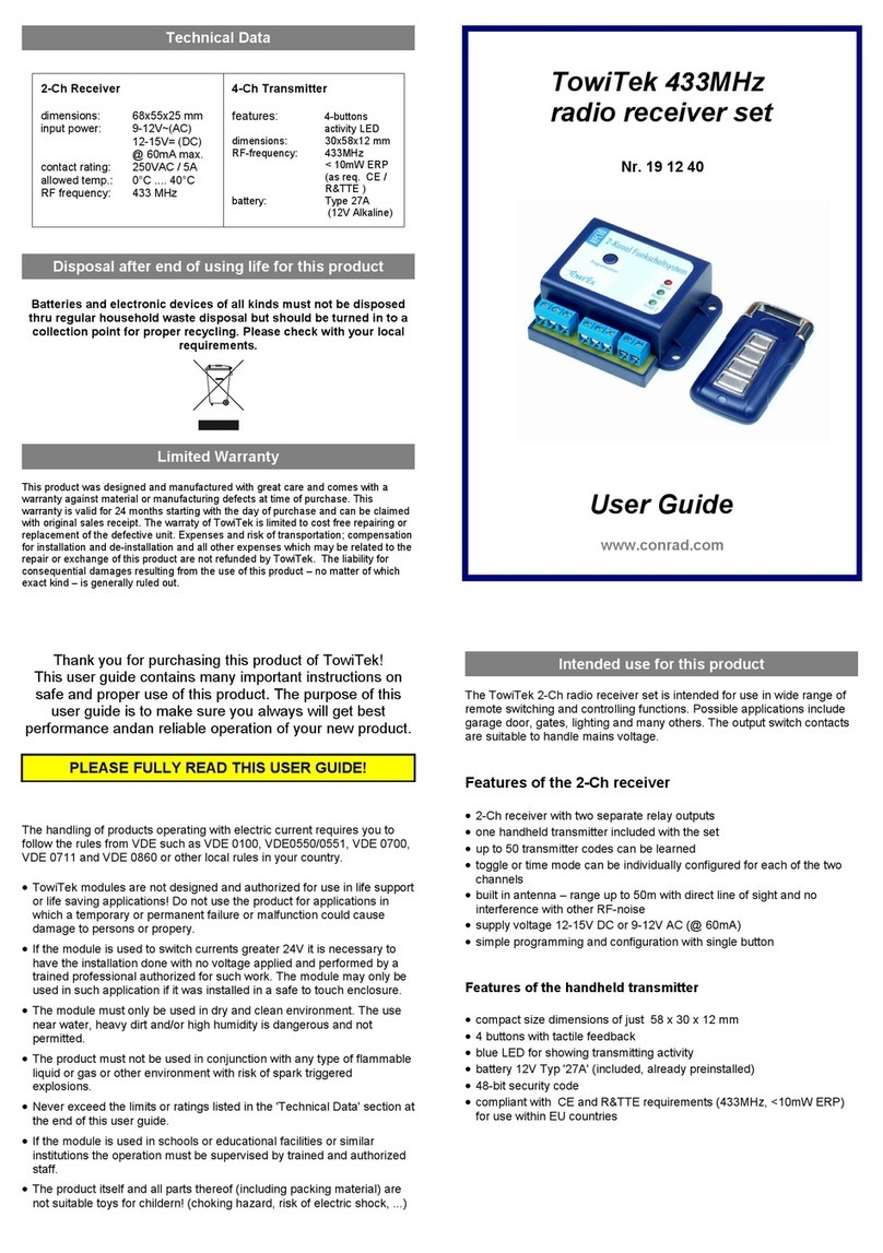
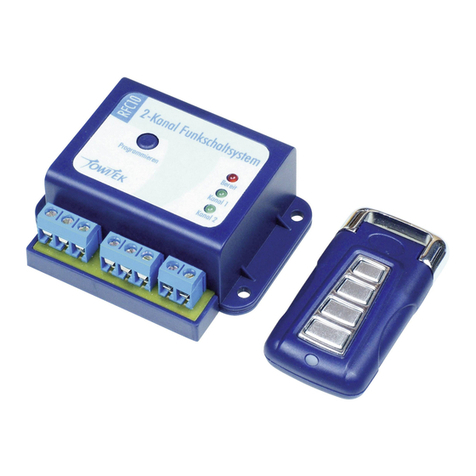
TowiTek 2564484 User manual

Bedienungsanleitung
433 MHz4-Kanal Funkempfänger-Set
Best.-Nr. 2564484
Bestimmungsgemäße Verwendung
Das 4-Kanal Funkschaltsystem ist für universelle Schalt- und Steueraufgaben mittels Funk-
handsendern vorgesehen. Anwendungsbeispiele sind z.B. Garagentore, Schranken,
Beleuch-tung uvm. Die Relais-Schaltkontakte sind für das Schalten von Netzspannung
(230VAC, max. 5A) geeignet.
Der Kontakt mit Feuchtigkeit ist unbedingt zu vermeiden.
Aus Sicherheits- und Zulassungsgründen dürfen Sie das Produkt nicht umbauen und/oder
ver-ändern. Falls Sie das Produkt für andere Zwecke verwenden, als zuvor beschrieben,
kann das Produkt beschädigt werden. Außerdem kann eine unsachgemäße Verwendung
Gefahren wie z.B. Kurzschluss, Brand, Stromschlag, etc. hervorrufen. Lesen Sie sich die
Bedienungsanlei-tung genau durch und bewahren Sie diese auf. Reichen Sie das Produkt
nur zusammen mit der Bedienungsanleitung an dritte Personen weiter.
Das Produkt entspricht den gesetzlichen, nationalen und europäischen Anforderungen. Alle
enthaltenen Firmennamen und Produktbezeichnungen sind, Warenzeichen der jeweiligen In-
haber. Alle Rechte vorbehalten.
Leistungsmerkmale des Empfängermoduls
• 4-Kanal Empfänger mit 4 Relais-Umschaltkontakten
• ein Handsender im Lieferumfang enthalten
• bis zu 50 Handsender-Codes einlernbar
• Ein/Aus (Toggle) oder Timer-Modus (Puls) für jeden Kanal separat einstellbar
• integrierte Antenne – Reichweite max. 50m bei freier Sichtverbindung zwischen Sender /
Empfänger
• Betriebsspannung 12-15V DC oder 9-12V AC (max. 200 mA)
• einfache Bedienung aller Funktionen über nur eine Taste
Leistungsmerkmale des Handsenders
• Kompakte Abessungen 58 x 30 x 12 mm
• 4 Tasten mit gut fühlbarem Druckpunkt
• Blaue LED-Kontrollanzeige
• Batterie 12 V Typ ‚27A‘ (bereits enthalten)
• 48-Bit Security-Code
• Konform mit CE und RED Bestimmungen (433 MHz, <10 mW ERP) für
genehmigungsfreien Betrieb in Europa
Aktuelle Bedienungsanleitungen
Laden Sie aktuelle Bedienungsanleitungen über den Link www.conrad.com/
downloads herunter oder scannen Sie den abgebildeten QR-Code.
Befolgen Sie die Anweisungen auf der Webseite.
Symbol-Erklärung
Das Symbol mit dem Blitz im Dreieck wird verwendet, wenn Gefahr für Ihre
Gesund-heit besteht, z.B. durch einen elektrischen Schlag.
Das Symbol mit dem Ausrufezeichen im Dreieck weist auf wichtige Hinweise in
die-ser Bedienungsanleitung hin, die unbedingt zu beachten sind.
Sicherheitshinweise
Lesen Sie sich die Bedienungsanleitung aufmerksam durch und beachten
Sie insbesondere die Sicherheitshinweise. Falls Sie die Sicherheitshinweise
und die Angaben zur sachgemäßen Handhabung in dieser
Bedienungsanleitung nicht befolgen, übernehmen wir für dadurch
resultierende Personen-/Sach-schäden keine Haftung. Außerdem erlischt in
solchen Fällen die Gewährleis-tung/Garantie.
• Beim Umgang mit Produkten, die mit elektrischer Spannung in Berührung kom-
men, müssen die gültigen VDE-Vorschriften beachtet werden, insbesondere
VDE 0100, VDE0550/0551, VDE 0700, VDE 0711 und VDE 0860.
• Das Produkt ist nicht für den Einsatz in Lebenserhaltenden oder lebensrettenden
Systemen oder ähnlichen Anwendungen konzipiert! Verwenden Sie das Produkt
nicht für Zwecke, bei denen im Falle eines Ausfalls, einer Störung oder einer
Fehl-funktion Personen- oder Sachschäden möglich sind.
• Wird der Baustein zum Schalten hoher Spannungen (> 24V) verwendet, darf die
Elektroinstallation nur in spannungslosem Zustand und nur durch einen sach-
kundigen Fachmann erfolgen. Der Baustein darf dann nur in Betrieb genommen
werden, wenn sie vorher berührungssicher in ein Gehäuse eingebaut wurden.
• Der Baustein ist ausschließlich für den Einsatz in trockener und sauberer Umge-bung
geeignet. Die Verwendung in unmittelbarer Umgebung von Wasser, grobem Schmutz
oder starker Feuchtigkeitsgehalten ist gefährlich und unzulässig.
• Das Produkt darf nicht in Verbindung mit leicht entflammbaren und brennbaren
Flüssigkeiten verwendet werden.
• Überschreiten Sie keinesfalls die elektrischen Grenzwerte, die unter ‚Technische
Daten‘ am Ende dieser Anleitung angegeben sind.
• In Schulen, Ausbildungseinrichtungen, Hobby- und Selbsthilfewerkstätten ist das
Betreiben von Modulen und Bausteinenschultes Personal verantwortlich zu über-
wachen.
• Das Produkt ist kein Spielzeug und kann für Kinder gefährlich sein!
(Verschlucken-der von Kleinteilen, Stromschlag ...).
Programmieranleitung
Die Handsender senden für jede der 4 Tasten eine einzigartige Kennung aus. Das Empfän-
germodul kann bis zu 50 solcher Kennungen lernen und dem Schaltkanal 1-4 zuordnen. Die
Zuordnung zwischen Tasten am Handsender und Schaltkanälen am Empfänger kann völlig
frei gewählt werden. Es ist möglich, dass ein Handsender mehrere Empfängermodule
steuern kann.
a) Einlernen von Handsender-Kennungen
Durch kurzen Druck auf den Programmiertaster am Empfänger gelangt man in den Lern-
Modus:
Programmiertaster
LED-Anzeige
Funktion
kurz drücken
Kanal 1 LED blinkt
Lernmodus f. Kanal 1
erneut kurz drücken
Kanal 2 LED blinkt
Lernmodus f. Kanal 2
erneut kurz drücken
Kanal 3 LED blinkt
Lernmodus f. Kanal 3
erneut kurz drücken
Kanal 4 LED blinkt
Lernmodus f. Kanal 4
erneut kurz drücken
LEDs aus
Lernmodus verlassen
Im Lernmodus wartet der Empfänger auf Kennungen der Handsender. Wird 10 Sekunden
lang keine Kennung empfangen, geht der Empfänger wieder in den normalen Betriebsmodus
zurück. Bei Empfang einer Kennung wird diese eingelernt und beide gelben LEDs blinken zur
Bestätigung.
b) Konfiguration der Schaltfunktion auf Wechsel- oder Zeitsteuerung
Durch langes Drücken des Programmiertasters am Empfänger gelangt man wie folgt in den
Setup-Modus für Kanal 1 oder Kanal 2:
Schritt 1: Kanal auswählen
Programmiertaster drücken und
LED-Anzeige
Funktion
loslassen, wenn...
Kanal 1 LED leuchtet
Setup-Modus Kanal 1
loslassen, wenn...
Kanal 2 LED leuchtet
Setup-Modus Kanal 2
loslassen, wenn...
Kanal 3 LED leuchtet
Setup-Modus Kanal 3
loslassen, wenn...
Kanal 4 LED leuchtet
Setup-Modus Kanal 4

Schritt 2: Betriebsart wählen
Die Betriebsart kann für alle Kanäle unabhängig voneinander eingestellt werden. Hierzu wird
noch während die LED von Kanal 1-4 leuchtet der Taster gedrückt, und...
Programmiertaster
LED-Anzeige
Funktion
erneut drücken und ...
langsame Punktfolge
Modus-Wahl
... nach 1. Blink loslassen
EIN/AUS Modus
... nach 2. Blink loslassen
0,5 Sek. Timer
... nach 3. Blink loslassen
5
Sek. Timer
... nach 4. Blink loslassen
30
Sek. Timer
... nach 5. Blink loslassen
1
Min. Timer
... nach 6. Blink loslassen
5
Min. Timer
... nach 7. Blink loslassen
15
Min. Timer
... nach 8. Blink loslassen
30
Min. Timer
... nach 9. Blink loslassen
1 h Timer
c) Löschen aller Handsender-Kennungen
um alle im Empfängermodul gespeicherten Handsender-kennungen zu löschen wird der Pro-
grammiertaster gedrückt gehalten, bis alle gelben LEDs gleichzeitig leuchten (nach ca. 6 Sek).
Während die LEDs noch leuchten wird der Programmiertaster erneut ca. 2 Sek gedrückt, um
die Komplettlöschung des Speichers zu bestätigen.
Die erfolgte Löschung wird durch ein Wechselblinken aller gelben LEDs bestätigt.
Die jeweils eingestellte Betriebsart für alle vier Kanäle wird bei diesem Vorgang nicht verändert.
d) Funktion und Bedeutung der LED-Anzeige im Normalbetrieb
Sind Funksender-Kennungen eingelernt, können alle Schaltkanäle unabhängig voneinander
gemäß der eingestellten Betriebsart gesteuert werden.
Die gelben LEDs für Kanal1-4 geben Auskunft über den Zustand der Relaiskontakte:
Leuchtet die gelbe LED, sind die Anschlüsse ‚NO‘ und ‚C‘ miteinander verbunden (Arbeits-
kontakt).
Ist die LED dunkel, sind die Anschlüsse ‚NC‘ und ‚C‘ miteinander verbunden (Ruhekontakt).
BITTE BEACHTEN SIE DIE MAXIMALE KONTAKTBELASTBARKEIT
Anschluss für externe Antenne
Die 3-polige Stiftleiste auf der rechten Seite der Klemmenleiste für die Stromversorgung dient
zum Anschluss einer optionalen externen Empfängereinheit. Wenn Sie den externen
Empfän-ger nicht verwenden, lassen Sie diesen Anschluss offen.
Funkreichweite:
Die Reichweite für die Funksteuerung beträgt unter optimalen Bedingungen bis zu 50 Meter,
kann aber durch Objekte zwischen Sender und Empfänger oder gleichzeitig aktive
Funksyste-me auf gleicher Frequenz (z.B. Babyphone, Wetterstation etc.) beeinträchtigt sein.
Batteriewechsel des Handsenders
Zum Tausch der Batterie des Handsenders (Typ 27A, 12V, Alkaline) werden die zwei Schrau-
ben an der Rückseite des Sendergehäuses gelöst und der rückseitige Deckel des Gehäuses
abgenommen. Die Polarität ist zu beachten: Der ‚+‘ Anschluss der Batterie muss zur flachen
Kontaktplatte zeigen. Verbrauchte Batterien dürfen nicht über den Hausmüll entsorgt werden
sondern sind bei einer vorgesehenen Sammelstelle abzugeben.
Montagehinweise
Das 4-Kanal Funkschaltsystem kann mittels dem Befestigungsflansch am Gehäuse an
nahezu jeder ebenen Fläche befestigt werden.
Mit den beiliegenden Halteklammern ist auch eine Rast-Befestigung auf DIN-
Montageschienen (30 mm Breite) möglich.
Konformitätserklärung (DOC)
Hiermit erklärt Conrad Electronic SE, Klaus-Conrad-Straße 1, D-92240 Hirschau, dass dieses
Produkt der Richtlinie 2014/53/EU entspricht.
Der vollständige Text der EU-Konformitätserklärung ist unter der folgenden
Internet-adresse verfügbar: www.conrad.com/downloads
Wählen Sie eine Sprache durch Anklicken eines Flaggensymbols aus und geben
Sie die Bestellnummer des Produkts in das Suchfeld ein; anschließend können Sie
die EU-Konformitätserklärung im PDF-Format herunterladen.
Entsorgung
Elektronische Geräte sind Wertstoffe und gehören nicht in den Hausmüll.
Entsorgen Sie das Produkt am Ende seiner Lebensdauer gemäß den geltenden
gesetzlichen Bestimmungen.
Sie erfüllen damit die gesetzlichen Verpflichtungen und leisten Ihren Beitrag zum
Umweltschutz.
Technische Daten
a) 4-Kanal Funkschaltsystem
Abmessungen............................... 93 x 55 x 25 mm
Stromversorgung........................... 9 – 12 V/AC / 12 – 15 V/DC / max. 200 mA
Schaltkontakte............................... Max. 250 V/AC / 30 V/DC / 5A
Zul. Temperatur............................. 0 bis +40 °C
Funkfrequenz................................ 433.92 MHz (433.05 - 434.79 MHz)
b) 4-Kanal Handsender
Ausstattung................................... 4-Tasten, LED-Anzeige
Abmessungen............................... 30 x 58 x 12 mm
Funkfrequenz................................ 433.92 MHz (433.05 - 434.79 MHz)
Sendeleistung............................... < 10 mW ERP (gemäß CE / RED)
Reichweite..................................... 50 m (im Freifeld)
Batterie.......................................... Typ 27 A (12 V Alkaline)

Operating Instructions
433MHz 4-Channel Radio Receiver Set
Item No. 2564484
Intended use
The 4-channel radio receiver set is intended for use in wide range of remote switching and
controlling functions. Possible applications include garage door, gates, lighting and many
others. The output switch contacts are suitable to handle mains voltage.
Contact with moisture must be avoided under all circumstances.
For safety and approval purposes, you must not rebuild and/or modify this product. If you use
the product for purposes other than those described above, the product may be damaged. In
addition, improper use can result in short circuits, fires, electric shocks or other hazards.
Read the instructions carefully and store them in a safe place. Make this product available to
third parties only together with its operating instructions.
This product complies with the statutory national and European requirements.
All company names and product names are trademarks of their respective owners. All rights
reserved.
Features of the 4-Ch receiver
• 4-Ch receiver with four separate relay outputs
• One handheld transmitter included with the set
• Each receiver could learn up to 50 transmitter keys
• Toggle or time mode can be individually configured for each of the four channels
• Built in antenna – range up to 50m with direct line of sight and no interference with other
RF-noise
• Supply voltage 12-15V DC or 9-12V AC (@ 200 mA max.)
• Simple programming and configuration with single button
Features of the handheld transmitter
• Compact size dimensions of just 58 x 30 x 12 mm
• 4 buttons with tactile feedback
• Blue LED for showing transmitting activity
• Battery 12 V Type 27 A (included, already preinstalled)
• 48-bit security code
• Compliant with CE and RED requirements (433 MHz, <10 mW ERP) for use within EU
countries
Up-to-date Operating Instructions
Download the latest operating instructions at www.conrad.com/downloads
or scan the QR code shown. Follow the instructions on the website.
Explanation of symbols
The symbol with the lightning in the triangle is used if there is a risk to your health,
e.g. due to an electric shock.
The symbol with the exclamation mark in the triangle is used to indicate important
information in these operating instructions. Always read this information carefully.
Safety instructions
Read the operating instructions carefully and especially observe the safety
information. If you do not follow the safety instructions and information on
proper handling in this manual, we assume no liability for any resulting
personal injury or damage to property. Such cases will invalidate the
warranty/ guarantee.
• The handling of products operating with electric current requires you to follow the
rules from VDE such as VDE 0100, VDE0550/0551, VDE 0700, VDE 0711 and
VDE 0860 or other local rules in your country.
• The product is not designed and authorized for use in life support or life saving
applications! Do not use the product for applications in which a temporary or
permanent failure or malfunction could cause damage to persons or property.
• If the module is used to switch voltages greater 24 V it is necessary to have the
installation done with no voltage applied and performed by a trained professional
authorized for such work. The module may only be used in such application if it
was installed in a safe to touch enclosure.
• The module must only be used in dry and clean environment. The use near
water, heavy dirt and/or high humidity is dangerous and not permitted.
• The product must not be used in conjunction with any type of flammable liquid or
gas or other environment with risk of spark triggered explosions.
• Never exceed the limits or ratings listed in the “Technical Data” section at the
end of this user guide.
• If the module is used in schools or educational facilities or similar institutions the
operation must be supervised by trained and authorized staff.
• The product itself and all parts thereof (including packing material) are not
suitable toys for children! (choking hazard, risk of electric shock, ...)
Operation
The handheld transmitters will send a unique digital code for each of the 4 buttons pressed. Each
receiver could learn up to 50 transmitter keys and associate them with one of the four relay
channels. The assignment between buttons on the transmitter and channel on the receiver can be
freely chosen. It is possible to use the same transmitter with several receivers.
a) Learning new transmitter codes
With short pressing of the programming key on the receiver the ‘learning mode’ is entered:
Programming key
LED
Function
Press short
Ch 1 LED blinking
Learning codes for Ch1
Press short again
Ch 2 LED blinking
Learning codes for Ch2
Press short again
Ch 3 LED blinking
Learning codes for Ch3
Press short again
Ch 4 LED blinking
Learning codes for Ch4
Press short again
LEDs off
Exit learning mode
In learning mode the receiver is waiting for codes received from transmitters. If no code is
received for about 10 seconds, the receiver will exit learning mode and return to normal
operation mode. If a code is received during learning mode, it is stored to memory and both
LEDs will flash for confirmation.
b) Configuration of the two channels for toggle or timer mode
By keeping the programming button pressed for longer duration the configuration mode can
be selected according to this procedure:
First step: choose channel
Press programming key and ...
LED
Function
Release, after...
Ch 1 LED is lit
Setup mode for Ch1
Release, after...
Ch 2 LED is lit
Setup mode for Ch2
Release, after...
Ch 3 LED is lit
Setup mode for Ch3
Release, after...
Ch 4 LED is lit
Setup mode for Ch4
Second step: choose desired mode
The mode of operation can be chosen individually for all channels. While the LED of Ch1 - Ch4
is still lit from first step the programming key is pressed again, and...
Programming key
LED
Function
pressed again, and...
slow blink sequence
choosing mode
...release after 1st blink
toggle mode
...release after 2nd blink
0.5 sec. timer
...release after 3rd blink
5 sec. timer
...release after 4th blink
30 sec. timer
...release after 5th blink
1 min. timer
...release after 6th blink
5 min. timer
...release after 7th blink
15 min. timer
...release after 8h blink
30 min. timer
...release after 9th blink
1 hour timer

c) Delete all transmitter codes from memory
For deleting all codes stored in the memory of the receiver the programming key is held down
until all four LEDs are lit together (after 6- 7 seconds). The key is released and pressed again
to confirm the deletion of the complete memory.
The completion of the memory formatting is confirmed with alternate blinking of both LEDs The
setting of the toggle/timer mode for both channels is not affected by this procedure.
d) Functions in normal operation mode
After learning codes from transmitters, all channels of the receiver can be controlled
independent of each other according to the configured operation modes.
The yellow LED for channels 1-4 indicate the current status of the associated relay.
If the LED is lit, the terminals ‘NO’ and ‘C’ of this channel are connected electrically.
If the LED is dark, the terminals ‘NC’ and ‘C’ of this channel are connected electrically
PLEASE DO NOT EXCEED THE MAXIMUM VOLTAGE OR CURRENT RATING
FOR THE RELAY CONTACTS
Maximum range to be obtained:
The functional range is up to 50 meters under best conditions but could be limited by objects
blocking the line of sight between transmitter and receiver. Other RF-noise on the same
frequency (e.g. from babyphone, wireless thermometer, or other 433 MHz devices) could also
limit the effective range of the remote set.
Changing the battery of the handheld transmitter
To replace the remote control battery (Type 27A, 12V, Alkaline), loosen the two screws on
the back of the transmitter housing and remove the back cover of the housing.
Observe polarity: The ‘+’ terminal of the battery must face the flat contact plate.
Used batteries must not be disposed of with the household waste, but must be returned to a
designated collection point.
External Antenna Connector
The 3-pin header on the right side of the terminal block for power supply is for the connection
of an optional external receiver unit. If not using the external receiver, please leave this
connector open.
Mounting instructions
The 4-ch remote receiver could be mounted on almost any even surface, mounting on metal
may have a negative effect on functional range. Using the included mounting clips, the case
can be snapped onto DIN mounting rails with 30 mm width.
Declaration of Conformity (DOC)
Conrad Electronic SE, Klaus-Conrad-Straße 1, D-92240 Hirschau hereby declares that this
product conforms to the 2014/53/EU directive.
Click on the following link to read the full text of the EU declaration of conformity:
www.conrad.com/downloads
Select a language by clicking on a flag symbol and enter the product order number
in the search box. You can then download the EU declaration of conformity in PDF
format.
Disposal
Electronic devices are recyclable waste and must not be disposed of in the
household waste. At the end of its service life, dispose of the product in
accordance with applicable regulatory guidelines.
You thus fulfill your statutory obligations and contribute to the protection of the
environment.
Technical Data
a) 4-Ch Receiver
Dimensions................................... 93 x 55 x 25 mm
Input power................................... 9 – 12 V/AC / 12 – 15 V/DC / max. 200 mA
Contact rating................................ Max. 250 V/AC / 30 V/DC / 5 A
Allowed temp................................. 0 to +40 °C
RF-frequency................................ 433.92 MHz (433.05 - 434.79 MHz)
b) 4-Ch Transmitter
Features........................................ 4-buttons, activity LED
Dimensions................................... 30 x 58 x 12 mm
RF-frequency................................ 433.92 MHz (433.05 - 434.79 MHz)
Transmission power...................... < 10 mW ERP (as req. CE / RED )
Transmission distance................... 50 m (line of sight)
Battery........................................... Type 27 A (12 V Alkaline)
Table of contents
Languages:
Other TowiTek Receiver manuals
Popular Receiver manuals by other brands
Texas Instruments
Texas Instruments PanelBus TFP503 manual

Sky Master
Sky Master DXS 23 operating instructions

Comfort audio
Comfort audio Programmer DT20 Technical bulletin
Audiodesign
Audiodesign PMU USB Series quick start guide
JVCKENWOOD
JVCKENWOOD KMM-BT408DAB instruction manual
GiBiDi
GiBiDi DOMINO DRS4334 Instructions for installation

Rocket Fish
Rocket Fish RF-WHD210 user guide

Pioneer
Pioneer VSX-1017TXV-K - iPod Ready, XM Satellite Specifications
Securitytronix
Securitytronix ST-CCTV-VBAC4 installation manual

IMG STAGE LINE
IMG STAGE LINE TXS-891 instruction manual

TV One
TV One 1T-CT-641 instruction manual

BOSSCO
BOSSCO MGV520B user manual
