manuals.online logo
Brands
  1. Home
  2. •
  3. Brands
  4. •
  5. Toyostove
  6. •
  7. Heating System
  8. •
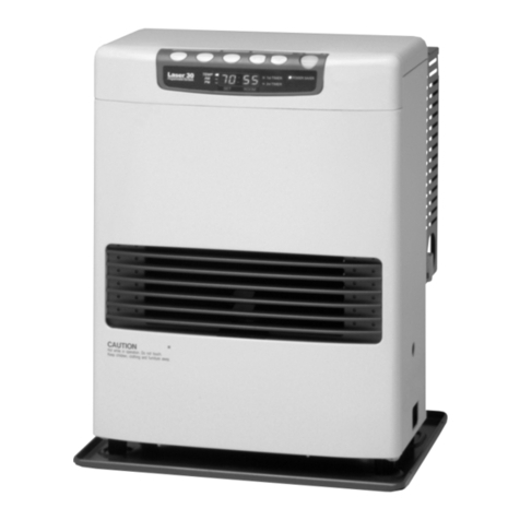
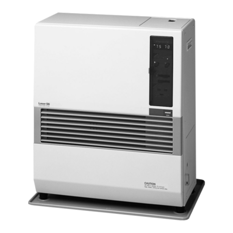
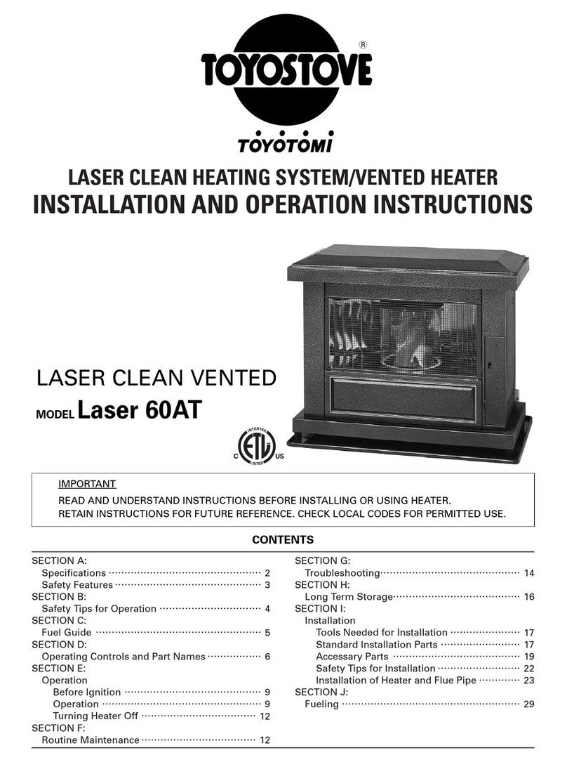
  9. Toyostove Laser 30 Type B User manual

Toyostove Laser 30 Type B User manual

LASER CLEAN HEATING SYSTEMJVENTED HEATER
INSTALLAT10N AND OPERAT10N INSTRUCT10NS
LASER CLEAN VENttED
M'DELLasgr
30 ф
(Type C〕
!MPORTAN丁
READ AND UNDERSTANDINSTRUCT10NS BEFOREINSTALLING OR USING HEATER.
RETAIN INSTRUCT10NS FOR FUTURE REFERENCEoCHECK LOCAL CODES AND ORDINANCES FOR PERMITTED USE。
CONTENTS
SECT10N A:
Specifications・
¨¨¨¨¨¨
・
・・¨"¨¨"。・・・¨¨………
¨
・・
2
SEC丁 10N B:
Safety Tips for Operation ¨ ¨¨¨¨¨・・…………¨…・。
3
SEC丁 10N C:
Fue:Guide ¨ "・・¨
¨
・
・¨
¨
・
・""・・・・・
・
・・""・・
・
・
¨¨¨¨・・・
4
SEC丁 10N D:
Operating Controls and Part Names ・ ・……¨¨
¨・
5
SECT10N E:
Operation
Before lgnition "¨ ¨¨¨¨¨¨¨¨¨¨¨…………・・¨
¨・・
8
0peration "¨ ¨"・・¨¨・・¨¨¨¨・・¨"・・¨・
・¨"・・
8
Turning Heater Off"¨ ¨¨¨¨¨・・¨"¨・・¨…………
…11
SECT10N F:
Routine ruaintenance・
¨¨¨"¨"¨"¨¨¨¨¨¨"¨。
12
SECT10N G:
Troubleshooting・ ¨¨¨¨¨¨"¨¨"¨¨…………
………。
14
SEC丁 10N H:
Long tterrn Storage ¨ "¨¨¨・
・
・
・
・
・"¨・
・・・
15
SECT10N l:
!nsta‖
ation
丁oois Needed forlnsta‖ ation・"¨¨……………
……16
Standard lnsta‖ ation Parts・ ・・¨¨・・¨……
…¨。
16
Accessary Parts・¨¨¨¨¨¨¨¨¨¨¨¨¨¨¨¨¨
¨
・・
18
Safety Tips for:nsta‖ation ¨
¨・・¨・・¨¨¨¨¨¨¨21
1nstaHation of Heater and Flue Pipe・
¨¨……¨・
22
Perrnanent Wiring lnsta‖
ation ¨¨¨¨¨¨¨"… 28
SEC丁 10N J:
Fueling ¨
¨¨・・¨¨・・¨¨"………・
・
…¨
・・・
・……
…・・
¨¨…29
SECTION A:
SPECIFiCATIONS
Model:
HeaterEfficiency:
HeatRating:
Fuel
Consumption:
Fuel
system:
FuelType:
Dimensions(WxHxD):
Weight:
VentPipe
Hole:
Maximum Length
of VentPipe
System:
ElectricalRating:
Laser
30
s0%
(1)
Hig,h
- 14,800BTU/h
Med
- 10,000BTU/h
Low - 5,200
BTU/h
High
-0.108
gal/h
Med
-0.076
gal/h
Low -0.040
gal/h
External
tank
(2)
ASTMD36991-K
KeroseneorASTMD396
No.1
5500
Low
SulfurNo.1FuelOil
16-15116"x 21-914"
x 13-9116"
31lbs.Empty
2-314"
- 3" diameter
10
ft.,3bendsorless
120
VoltsAC,
60
Hz
Preheat
-260W
Burning
-
26W
600squarefeet
(0"F)
720
squarefeet
(20'F)
Typical
RoomSize
(3):
Heat
and vaporizedwater are producedby the combustion process
of this kerosene
heater.This rating
doesnottakeintoaccountheat
lossdueto condensation
ofwatervapor.
External
tankto bepurchased
from local
suppliers.
0" FHeatLoad = 24 BTUlft'lhr
20" F Heat Load = 20 BTU
lft'lhr
Roomsizefor whichthis heateris suitable
will vary dependingon outsidetemperature,house
insula-
tion,window size,andotherfactors.
2  3
SECT10N B:
SAFETY ttIPS FOR OPERAT10N
CAUTION:
Heaterand vent pipe system must be properly installed
beforeoperation.Pleasefollow
instructionsunder
"lnstallation",
Sectionl.
1. Neveruseanyfuel otherthan ASTM D36991-KKerosene
or ASTM D396
No.1
5500
LowSulfurNo.1Fuel
Oil.
NEVER
USE
GASOLINE.Useof gaso-
line
can
lead
to uncontrollable
flames,resulting
indestructivefire.
2. Dueto high
surfacetemperatures,
keepheater
away
from children,
furniture
andclothing
whilein operation
(See
Page22l-.
To prevent
abnormal
operationand prolong
heaterlife,be sure
to perform
routinemaintenance
(See
Pages12-131.
4. Neverstoreortransport
fuelinother
thana metalor plastic
container
thatis
(1)acceptable
for fuel,
(2)
non-red
in color,and (3)
clearly
marked,
"KEROSENE"
or"NO.
1FUEL
OlL".
Neverstore
fuelin
the
living
space.
5. Operating
Temperature
Range
Useheaterwithin the range
of temperatures
indicated
in
the rightfigure.
Point
A: lf outside
temperature
-20"F
than room temperaturehas
to be OoFor above
PointB: lf outside
temperature
-45oF
than room temperature has
to be 60"For above
R:GHT WRONG
︵﹂
︒︶Φ ﹂ コ
一o ﹂ Φ
aC C
O 卜の
0一 ∽一コ
O
RoomTemperature
("F)
SECT10N C:
FUEL GUIDE
TheToyostove
Laser
30is
designed
for usewithASTM
D3699
1-KKeroseneor ASTMD396No.15500Low
Sulfur
No.1
Fuel
Oil.
Useoflow-qualityfuelwillcauseburner
performance
todrop,
leadingto abnormalcombustionand
reducedheater
life.
Purchase
only
ASTM
D36991-KKerosene
or ASTMD396No.1
5500
LowSulfur
No.1Fuel
Oil in non-red
cans
reservedexclusively
for fueland marked
accordingly
with theword "KEROSENE"
or "NO. 1 FUELOlL".Always
store
your
fuelina separateareafromwhere
youstore
gasoline
foryourpower
equipmentto avoidaccidentaluse
of
gasoline
in
your
heater.
Whatto Buy. . .
ALWAYS: Cleanand high-qualityASTM D36991-KKerosene
or ASTM
D396No.1
5500
Low
Sufur
No.1Fuel
Oil.
ALWAYS: Fuelfreeof contaminants,
wateror cloudiness.
NEVER: Gasoline,alcohol,
white
gas,
campstovefuelor additives.
NEVER: Yellowor sour-smellingfuel.
How to Store lt . . .
ALWAYS: Store in a clean container,non-red in color, clearly marked
KEROSENE
or NO.1FUEL
OlL.
ALWAYS: Storeaway from directsunlight,heat
sourcesor extremetem-
perature
changes.
NEVER: In
aglass
container,oronethathas
beenusedfor otherfuels.
NEVER
: For longerthan six months. Begin
eachheating
season
with
fresh
fuel;discard
atthe endof season.
NEVER: In
theliving
space.
Why ltislmportant...
Pure,
clean
fuel is essentialfor safeand efficientheater
operation.
Poor
quality
orcontaminatedfuel
cancause:
oExcess
tardepositson burnerandflue
pipe
oIncomplete
combustion
o Reducedheaterlife
Use
ofa highlyvolatileflammablefuel
suchas
gasoline
can
produce
uncon-
trollable
flames,
creating
a severe
fire hazard.
SECT10N D:
OPERATING CONTROLS AND PART NAMES
Before
usingheater,familiarize
yourself
with thefollowing operatingcontrolsand names.
嘔 □ 裏11は ず
ER SAVR
6.Powersaverlamp
8.lst T:MERlamp
7.2nd TIMER lamp
1. ON/OFF
switch: Main switchturns heateron and off. When switchedon, heater
begins
operationandcombustion
startsafter
preheat
period.
2. PowerSaverbutton: ThebuttonturnsPower
Saver
operation
modeon andoff.
3. Timerbutton: ThebuttonturnsTimeroperation
modeonandoff.
4. Temp./Timer/Clock
set: Temp./Timer/Clockset modescan be set by pressing
UP/HOURor
DOWN/MINbuttons.
5. Power
lamp: Lit - Heaterisinoperation.
Flashing -Pre-heating
and
pre-purging.
6. Power
Saver
lamp Heater
operating
inPower
Saver
mode.
7. 2ndTimerlamp: Heateroperatingin2ndTimersettingmode.
8. 1stTimerlamp: Heateroperatingin 1stTimer
setting
mode.
9. Digitalindicator: Displaysclock,sbttemperature,roomtemperatureanderrorcode.
10.Temperature
lamp: Lit -DigitalIndicator
shows
setandroomtemperature.
Flashing -Settemperaturecanbechanged.
11. AM lamp
/ PMlamp Lit -Digitallndicator
showscurrenttime.
Flashing -
Current
timecanbechanged.
12. Circulation
fan: Three
speed
motor
supplieshigh-capacitywarm airflow duringhigh
combustion
for heating
room up quickly,
andlowor medium-capaci-
ty warm airflow during
low or medium
combustionfor maintaining
comfortable
roomtemperature.
13. Room
temperaturesensor:Constantlysensesroom temperatureand suppliesinformation
to
heater
sothatdesiredroom
temperaturecanbe
maintained.
14. Powersupplycord: Forusein 120V,AC
electricaloutlet.
15. Plumbbob: Allows
userto checkif heaterislevel.
η
│
REF# PART# PART NAME REF# PART# PART NAME REF# PART# PART NAME
123
456
7
8
9
10
︲︲
︲
2
︲3
︲4
︲
5
︲6
︲7
︲8
︲
9
20
2︲
22
23
24
25
26
20479546
20479660
20479676
20479563
20479564
20479551
20479553
20479550
20450007
20479540
20479566
20479529
20479570
20479552
10005597
20479592
20479510
20479581
20479509
20479508
20479582
20479593
20479543
20479542
20479594
20474011
Frontpanel
assembly
Top plate assembly
Indicatorlamp circuit
Rightsidepanel
Left side panel
Rear
guard right
Rear
guard left
Rear
guardtop
Plumbbob
Circulationairfilter
Rear
panel
Driptray
Adjustableleg
Levelerfuel pipe
Fusible
linkvalve
Joint gasket
Heat
chambercover
Upper gasket
Heat
chamber assembly
Heatelement
Lower gasket
Heatchamber gasket
Burnerring
Burnerassembly
Burner
gasket
Primarvflame rod
27
28
29
3︒
3︲
32
33
34
35
36
37
38
39
4
0
4︲
4
2
43
44
4
5
46
47
48
49
5
0
5︲
52
20479573
20479612
20474083
20475834
20479518
17185580
20474920
20475831
20475881
20479544
20479591
20479530
20479531
20479637
20479683
20479669
20479671
20478317
20478306
20478534
20479519
20479541
20475535
20478373
20479891
20479521
Burnerthermistor
Main circuitboard
Fuel nozzlegasket
Fuelnozzle
lgniter
lgniter gasket
lgnitercover
Micawindow
Peepwindow gasket
Heat
exchanger
Reliefgasket
Pressure relief plate
Relief
spring
Blower motor assembly
Air intake fan
Circulationfan motor
Circulationfan
Transformer
High limit switch
Fuelsump
Fuel
pump
Fuel
pipeassembly
Power supply cord
Thermistor
Standardflue pipe
loniter ouide oasket
53
54
5
5
56
57
58
59
60
6︲
62
63
64
65
66
67

69
7︒
7︲
72
73
74
75
76
20479513
20474955
20479574
20450120
20474052
20474051
20475553
20450017
20479556
20474050
20474048
20479585
20474925
20479584
20474975
20474951
20474977
20479511
20479567
20479568
20479586
20455862
20479694
20479698
Burnermat
Insulatingcloth cover
Blower motor gasket
Screw for igniter unit
Screw E
Screw D
Screw 1P
Screw 1rA
Screw 1M
Screw C
Screw B
Outside nozzlegasket
Oil catch
Bent
joint
L-shaped hose
lnlethose
Hose band
Flame rod gasket
Air damper
Air joint gasket
Draft tube
Screw 52
lnstructionmanual
Carton
SECT10N E:
OPERAT10N
BEFOREIGNITION
1. Openthe Valve(s)
Openthe valve(s)
ofthe external
fueltank.
2. Start the Fuelflow
lf usingheaterfor the first time, or afterheater
hasbeenout of fuel, press
the red reset
button oncefor a periodof one secondin orderto sendfuel
tothe
fuel
sump.
Note: Make
surethere is nofuel leakage
from thefuel lineorjoints.
Also makesurefueltank isnottoo high.
See
installationinstructions.
3. Plugin the Heater
Plug heater into a 12OYAC electricaloutlet. On digital indicator pre-set
"Two Dashes"will beshowing.
Note: Do notconnectto an outletshared
with otherappliances.
4. Set Clock
lmportant: Clockon the heatermust alwaysbesetto currenttime.
Press
'HOUR' and"MlN" buttonto correcttime.
Note: 'HOUR' or "MlN" button
will changethe
timeeveryone
(1)
unit.
Holding
the buttoncontinuously
will causethetime to changerapidly.
Note: Inthe eventof a power failure(morethan approx.20 min.)all clockand timer settingarecan-
celled.
lst T!MER 2nd丁:MER POWER SAVER UP′ HOUR DOWNIMiN
lstT;MER O PowER
sAVER
OPERAT10N
MANUAL OPERAT10N
Operation of the heater is under the direct contro:of the user.Heat output wi:│′ however′ be automatica‖ y
adiuSted in accordance with the roo日
n tennperature registered by the ternperature sensor.
Reset
button
:日∫
日
1. Turn HeaterON
A. Press
ON/OFFswitchto "ON" position.
The current room temperatureand the settemperature
will
beshownonthedigitalindicator.
POWERlamp
will startto flash
and
thenblowermotor
andignition
will start.
This
lampwill continueto flash
duringthe preheating
time.
B. After
approx.
1.5
- 4 minutesignition
will take
place.
(*)
Afterignition,
power
lampwill changeflash-
ing
to continuous.Circulationfanwillturn on afterapprox.2 minutes.
Note: {*) Pre
-heating
dependson the room temperature.
Room
temperature: below 34'F Approx. 4 minutes
34"F
-61oF t, 2 minutes
over 61"F tt 1.5minutes
POWER SAVER
鰊鰊 鰊 鰊 鋏
T:‖ P::〔 Fll[]]flII::] ::1ll‖
il ・
P°WER SAVER
2. Adjusting Room Temperature
A. Press
'UP" or "DOWN" button.
Temperaturelampwill startto flash.
Note: UUP'
or "DOWN" buttonwill change
thetemperatureevery
2oF.
B. Press
"UP' or "DOWN" button as required.Room temperaturecan be setfrom 50"Fto 90"F.
(lnitial
setting
:70'F)
Note: Desiredtemperaturesetting
will bedisplayedon the digitalindicatorwhen you setthe room
temperature.
C. When room temperature reachesthe selectedsetting,heaterwill automaticallyshift to "MED" or
'LOW' burning
modeto maintainthedesiredtemperature.
When room temperatureexceedsthe selectedsetting by approx. 4"F,the heaterwill automatically
shut off. As room temperaturedrops,the heaterwill automatically
re-start
to maintainthe desired
temperature.
lst T:MER 2nd TIMER POWER SAVER UPrHOuR DOWNノ M!N
lstT1MER @ PowERSAVER
呵
l―
ll
Approx. +
Approx. +
SET
TEMP /
Medium Low Off Re-lgnitionHigh
POWER
SAVER
OPERATION
The PowerSavermode reducesthefrequency
of ignition
actions,to save
electricconsumption.
Press
the POWER
SAVERbutton "ON" to startthe operation
ofthe "POWER
SAVER".
Whenthe room temperatureexceedsthe selectedsettingby approximately
10"F,the heaterwill automatical-
ly shut off.As the room temperaturebecomes
lowerthan the selectedsetting,
the heaterwill automatically
re-start
to maintainthe desiredtemperature.
● lstTIMER O POWER SAVER
●2nd T!MER
Approx. +
Approx. +
ぴ  T
High
/
Medium Low Off Re-lgnition
SET
TEMP
TIMER
OPERATION
"TIMER' operation
is programmed
for particular
time of hour and temperature,
in orderto saveenergy
when
theheaterisusedatnight
orwhile
you leave
home.
NOTE:The Laser30has
a dualtimer feature
(this
isnot an automaticsetback).
The timer featureallows a userto manually lower the temperature
(setby user)
until a certaintime of day
(set
by user)by pressing
atimer button.This button must be pushed
eachtime you want thetemperature
to
drop back.
lt is not automatic.There are two timer buttons on the Laser
30, 1st
timer and 2nd timer. This
affows for two different
temperaturedrop backs
per
24hour period.
Examplelst Timer:
Your normal room temperatureis set for 70 degrees.You
workfrom 8 am until5pm.
Youwant
theroom
temperature
to
drop to 62 degreeswhile you are at work and you want the
room to return
to 70degreesat 4 pm so it will bewarm when
you get home.Whenyou leave
for work you must press
the
1st
timer buttonto activatethe timer.
The
temperaturewill
dropto 62degreesandreturn
to 70
degreesat
4pm.
Example2nd Timer:
Your normal room temperatureis set of 70 degrees.When
you go to bed, you want the temperatureto drop to 65
degrees.
You get up at 6 am and want the room warm
when you get up.When you go to bed,
you must pushthe
2nd timer button to activate
timer. The temperaturewill
drop to 65 degrees
and staythere untilthe time at which
you set
(5:00
am)
the until
to return
to normal
temperature.
Press"1st" Timer Press
"2nd" Timer
button.
(7:00AM) button.
(11:00PM)
10
Setting 1stTimerl2nd Timer:
1.
Make
suretheclock
is
set.lfnot,
press
thehour
andminute
buttonuntilthe
correcttime isindicated.
2.Press1stTimerbutton.
Usethe upanddown arrowsto setthetime at
which
you want
the room
to return
to normal
temperature.
Thiswould be 4:00PM
to have
the room startheating
up at 4 pm. You have
ten
seconds
fromthetimeyou push
thebutton
to enterthissetting.
3.Afterten secondsthe display
will changeto Temp.TheTemp sideof the display
will showthe default56
degrees.Usethe up arrowto adjustthistemperature
settingto the desired65degrees.
The lst Timer is
now setandyou arein the 1st
timer mode.To return
to the normal
operation
mode,
press
the 1st
timer
button.lf you want to setthe 2ndTimer, press
2ndTimer button and repeat
the process
with the desired
settings.
To returnto normal
settingonceatimerhas
been
pushed
(example
achild
press
1st
timer buttonand
you
don't
want
thetemperature
lowered)
just
press
thebuttonagain.
Note: The heateroperatesat the same hour and at the same temperature,
if it has once been set for
such
hourandtemperature,unlesstheirsettingsarechanged.
Note: lf a power failureoccurs
(for longer
than 20 minutes)
while in operation,time and temperature
settingsarecancelled.
Whenthis happens,
"AM", and "PM" lampsstart
flashing.Reset
desired
timesandtemperatures.
Note: To cancelthe timer operation,
press
the "1st" Timer button or the "2nd" Timer button again.
Ordinaryoperation
willthen berestored.
Note: After the heaterhas beensetfor a particuler
hour and temperatureit will operate
at that setting
each
timethetimer button
is
turnedon unlessthesettingsare
changed.
MANUAL
COMBUSTION
lmportant: Thisfeatureisfor testing purposeonly!
This heater
alsocan be keptburning at desiredcombustion
mode (High,
Medium or low) manually,
regardless
of room
temperature.
1. Press
the "UP-HOUR"button and "DOWN-MIN"button atthe sametime for more than three(3)
seconds
when
ON
/ OFF
switch
is "ON".
2. P1,P2
or P3will bedisplayedon the Digitallndicator;
P1
= Low mode
P2
= Medium mode
P3
= Highmode
Thenselect
desiredcombustion
mode by pressing
"UP-HOUR"
or "DOWN-MlN" button."UP-HOUR"
buttonchanges
combustion mode to higher,"DOWN-MlN" button changescombustion mode to lower.
3. To clear,
press
the "UP-HOUR" button and "DOWN-MIN" button at the same time for more than (3)
secondsuntil
normaltemperatu
re
display
returns.
TURNINGHEATER
OFF
PressON/OFFswitchto "OFF"position.
POWERlampwill flashandwill go out.Circulation
fan and blower
motorcontinue
to runfor approx.three
(3)
minutesto cool down the heater.Makesure
POWERlampgoes
out
whenthe
fanstops.
T:‖ Pヨ
[III:]│:│]:][]] ::ill‖ 1 °
P° WER SAVER
餡鰊 餡 鰊 魏
SECT10N F:
ROUTINE MAINTENANCE
CAUTION: Besureto unplugheater
before
performing
anychecksor cleaning.
CAUTION:Allow heater
to coolcompletely
beforecleaning
or maintenance.
FOR
OPTIMUM
HEATERPERFORMANCE,
THEPARTS
SHOWNBELOWSHOULD
BE
CLEANED
REGULARLY:
1. GleanLouvers
(ONCE
AWEEKI
Dustandstainsshouldbewipedoff
louvers
with
adampcloth.
2. CleanCirculationAir Filter (ONCE
A WEEKI
A meshfilter islocated
on heatercabinetrear
side.
Oncea week slidethe filter up to remove and it
shouldbe
vacuumed
clean.
3. Checkfor FuelLeaks
(REGULARLYI
Makeit
ahabit
tocheck
for
anysignof
fuelleakage
along
the
fuellineandat
all
joints.
Fuelleaksmayleadto risk
of
fire.
4. Check
FluePipe
Area
(ONCE
AWEEKI
Checktheflue
pipe
joint
to make
sureconnection
is
firm.Useavacuum
cleanerto remove
anydustor
pet
hair.
Circulationair
filter
12
5. CleanFuel
Strainer
(ONCE
A MONTHI
The strainerof the fuel sump should be cleaned
oncea month and before
storingheater
atthe endof eachseason.
(a) Closethe valve(s)ofthe separate
fueltank.
(b) To catchthefuelwhich will drainout,setthe oil catchbelowthe strainer
cover,
with asmallcontainerunderit.
(c) Loosenthetwo screws
from the strainercover
and remove.
(d) Removethe strainerandwashwith fuel.
(e) Return
the strainer
to its original
position.
Replacestrainer
coverand
screw
to secure.
(f) Wipe
awayanyspilled
fuel.
(g) Openthe
valve(s)ofseparatefuel
tank.Check
forfuelleakage.
Note: Be sureto unscrewthe drain screwto remove all remainingfuel
from thefuelsump atthe endof eachseason.
AUTOMATICIGNITER
CLEANINGSYSTEM
Theignitercleaning
mode
prolongs
theigniter
life.
Theheaterwill automaticallyclean
igniter
everydayat2:00a.m.anddisplay"Cl" on digital
indicator
ifheaterisrunningatthattime.
To clean
igniterheaterwill automaticallystopat 2:00
a.m.
andautomaticallyre-igniteandcontinue
burning
again.
o n︐
13
SECT10N G:
丁ROUBLESH00T:NG
NOTE BEFORE REQUESTING REPAIR AND SERViCES
The
following
symptoms
arenormalduringoperationoftheheater.
CONDl丁 :ON REASON
.
O①
󰿯∽
一ョO
E
E叉一0
﹄0
0Φ
だ0
一∽∽一﹄①
一O①
ECO
󰿯>>
White smokeor smellat initial
useafter
pur-
chase. Machineoil or dust burns off the surfaces
of
the burneror heat
exchanger.
Flamesflashingfor a few minutesafterigni-
tion. The burner
iscoldand igniteris keptrunning
for a
while
after
ignition.
Occasionally
makes
"cracking"
noisewhen
heaterisignited
orextinguished. Expansion
andshrinkageof metal
parts
when
they
are
heatedorcooled.
Warm airwill notblow assoonasignited. To preventuncomfortable
cool air from com-
ing out at the beginning,circulationfan start
up is
delayed.
Audiblechugging
sound
from fuel pump
when started
firsttime or after runningout of
fuel.
Air is in the pump. However,noise
should
stop
within 1minute.*
.
C O
󰿯0 ﹂ O
a
OC
一
の
一﹄0一〇0
こC O
󰿯 > >
"Ticking"
noise. Noise
of
fuel
pump inoperation.
Normal.
Occasional
yellow
flickeringin blue
flame. Normal.
*lf soundfrom fuel
pumpdoesnot
decreaseandheater
shutsoff,check:
1. Pushredreset
buttononfuel
sump.DONOThold
down.
2. Insure
thatallvalvesareopenandfilteris
clear.
3. Insure
external
fuel
tank
hasfuel
and
filters
areclean.
Shouldproblems
ariseduring operationor ignition,
usethis chartto determinethe causeand the proper
steps
to take.Besureto unplug heaterandallowto coolcompletelybeforetakingcorrectivemeasures.
Inthe eventthat heatershouldextinguishitself,without anyactionor your part,you should
look
to thedigi-
talindicatorfor anyofthefollowingerrorcodes.
ERROR CODE CAUSE SOLU丁 10N
EE6
EE2 Fuellinemalfunction
Outof fuel Consult
yourdealer.
Check
fuel
gauge
onfuel
tank;
refuel.
EE8 Blower
motor
malfunction Consult
yourdealer.
EE 12 Highlimit switchactivated Cleancirculation
fan filterand remove
any
obstructions,
allow
your heater
to coolcom-
pletely
andre-ignite.
EE 13 Burnerthermistor
failure Consult
yourdealer.
EE 22 lgnitionfailure
three
times Consult
yourdealer.
14
SECT10N H:
LONG TERM SttORAGE
At the closeof eachheating
season,
or when you do not plan
to use
your heaterfor an extended
period,
the
following procedures
arerecommended.
1. As the end of the seasonapproaches,
calculate
your fuel purchases
so that you can use up all the fuel
you haveon hand.When fuel is storedfor over six months,itsqualitymay deteriorate.The useof such
fuelwill have
an unfavorableeffect
on heater
operation.
2. lfyour heaterneedsany serviceor repair,
now is
the time to call
your dealer
andget it done beforestor-
age.
Thatway your heater
will bereadyfor immediateuse
when the nextheating
seasonbegins.
3. lfyou plan
to store
your heaterin place,
(a) Unplug
heater.
(b) Closethemain
tank
valve.
(c) Remove
all
fuelfrom the
fuel
sumpandcleanthefuel
strainer.
(d) Wipe off any stainsor duston heaterwith a damp cloth,
then wipe once
againusing
adrycloth.
(e) Cover
heater
completely
with a large
plastic
bagto protect
from dust.
4. To store
heaterin another
location,
(a) Unplugheater.
(b) Closethemaintank
valve.
(c) Remove
all
fuelfrom the
fuel
sumpandcleanthe
fuel
strainer.
(d) Disconnectfuellineandfluepipe
fromthe heater.
Note: Fuel
remainingin the fuel line may flow out when fuel line is
disconnected.
Have
acontainer
ready
to catchdrainage.
(e) Removeany sootaccumulatedinthe flue pipeusinga brushand/or
vac-
uumcleaner.
(f) Wipe off any stainsor duston heaterwith a damp cloth,then wipe once
againusingadrycloth.
(g) Putthe heaterin the original shipping box, and store in a dry place.
lf
originalshipping box is not available,coverthe heater
completely
with
a large
plastic
bag
to protect
from dustduring storage.
(h) Plugexhaust
and air intake
openingsof the flue pipeby using
optional
caps.
(Part
#20474945and #204749491
TRANSPORTATION
Takethefollowingmeasures
toavoid
fuelleakage
duringthetransportationoftheheater.
-Alwaysmovetheheaterinan
upright
position.
-Always
drain
fuelfrom
the
fuel
sumpbefore
transportation.
15
SECtt10N l:
INSTALLAT10N
T00LS NEEDED FOR INSTALLAT10N
Tool
Phillips
Head
Screwdriver Installationofflue pipe,
etc.
ElectricDrill Drillingholeinwall
forflue
pipe
HofeSaw,2-3hto 3" diameter Makinghole
inwallforflue
pipe
STANDARD
INSTALLATIONPARTS
The following standardinstallation
parts are enclosed
with heater.For alternate
installation
methods,
you
may needto purchase
additional accessorieswhich are available
from your TOYOSTOVE
dealer.See
"AccessoryParts".
DripTray
(1) (PART
#204795291
讐
嘗
7
VVa‖Brackets{2 sets){PART#20479562}
PipeHolder
(1) (PART
#204749631 Pipe
Stopper
(1) (PART
#204749641
16
{3) 0
Flue Pipe{1} {PART#20479891)
Exhaust Air Cap{1) (PART#20479845)
lntake Air Cap(1) (PART#20474949} inlet Hose(1)(PART#20474951)
Bent Joint(1)(PART#20479584) L―
Shaped Hose(2){PART#20474975}
Oil Catch{1){PART#20474925) Hose Band(2)(PART#20474977)
lnsulating Cloth Cover(1)(PART#20474955)
(3}
Spacer{1)(PART#20478967)
17
ACCESSORY
PARTS
Thefollowing accessory
parts
areavailable
for usein non-standard
installationof the Laser30.After giving
carefulconsiderationto your desired
heaterand flue pipe locationsand fuelingsystem,consult
your
TOYOSTOVEdealerto purchase
the necessary
accessory
parts.
lmportant: Use only genuine
TOYOSTOVE
partsfor you heater.Use of unauthorized
generic
or other
brandparts
canseverelyreduce
performance
andsafety,
andwill invalidatefactorywarranty.
Accessory Part No. Application
Extension
pipekat
(L)* 20479898 Extends
pipesystemby 61-31+to78-31{'
Extensionpipe kit (M)* 20479897 Extends
pipe system by 22-tlz
to 39-3/a"
Enension pipe kit (S)* 20479896 Extendspipe system by 12-sleto 19-5/s"
L-Shapedexhaust
joint* 20479861 For
90degree
bendin exhaust
pipe
Fuellifter
pump 20477500 Usedto lift
fuelto heaterwhen fueltank is located
underground
ModelOPT-91UL or outdoorsin
a position
lowerthanthe heater.
With automatic
recovery.
E>ctension
flue pipe 20479887 Forinstallationinwallthicknesses
from 9 inches
to 13inches.
ExternalFuel
Supply 10005098 Forinstallation
of externaltanksystem
InstallationKit
Pressure
reducingvalve 10005099 SeeNoteon page
29.
x Total lengthof extension
pipe betweenheater
and flue pipe must be no greater
than 10
ft. No more than
three
bendsmaybeusedinextension
pipe.
Fue:Lner Pump Mode1 0P■ 91 UL Pipe
Support
Hardware
PART#20474950
L-Shapedexhaust
joint
PART#20479861
PART#20474951
PART#20479872
!nsu!ating c:oth cover
l― 
彎り司
PART
#20474954
PART#20479853
Adjustable Exhaust Pipe
22‑7t:[「
二
'I[ト
饉 騨
PART#20474955
Flue pipe entension
PART#20479887 Flue pipe ext{for wa‖ up to ・9〜13・
)
PART#20479873F!ue pipe ext.(for wa‖ up to・13〜16・
)
PART#20479874F!ue pipe ext.(for Wa‖ up to‖16〜20m)
PART#20479875 Flue pipe ext(for wa‖ up to m20〜24")
External Fue:Suppiy
18
EXTENS10N KIT
Extension Pipe Kit{L} PART#20479898
靱町
①
(#20479861) (#20474963)
⑥ け 20474950
Pipe Support Hardware
Pipe Holder (2 pcs.)
Pipe Holder Support (1 pc.)
◎
Nut{l pc}
(#20474955)
No Name of Part Qty
①Adiustable Exhaust Pipe
Max.39-3le- 22-7|rs
②Exhaust Extension Pipe
(long, 39-r/einch)
③Intake
Pipe(80inch)
④Insulatingcloth cover
(40inch)
⑤Pipe Holder
⑥PipeSupport Hardware
3
e
t
⑦L-ShapedExhaustJoint
When usingthe "Extension
pipe (L)" extension
kit,
the distance
between the heater exhaust pipe connection and the flue pipe
connection must be at least 63-s/einch but no more than 80-1/2
inch.
(See
Figure
1for reference.)
INSTALLA丁 10Nヽ〃ITH EXttENS10N PIPE KIT{L)
伊
嗜与テ
ゴWL膨
Adjustable
ExhaustPipe
Insulation
cloth covel
Exhaust Extension
Pipe
(long)
e
NOTE:
Use
"L"-shaped
Exhaust
Jointif necessary.
19
Extension Pipe Kit {Ml PART#20419897
「
MaК39%〜
T.1
h司
(#20474951)
{#20474955)
{#20474963)
Pipe Ho:der{2 pcs)
PipeHolder Support (1 pc.)
◎
Nut(l pc.)
Screw Wood Screw
{l pC.) {2 pcs.)
No. Name of Part Qη Figure2
①Adiustab:e Exhaust Pipe
Max.39‐
,′
8〜Min.22‐
7/16 1
②!ntake Pipe(40 inch)
③lnsu:ating c:oth cover
{40 inch) 1
④Pipo Ho:der
⑤PipeSupportHardware 2
0
t
⑥L‐Shaped Exhaust Joint
When usingthe "Enension pipe (M)" extensionkit, the distance
between the heater exhaust pipe connection and the flue pipe
connection must be at least 25-5lsinch but no more than 42-1/z
inch.
(See
Figure
2for reference.)
E離ension Pipe Kit〔S〕 PART#20479896
一
一
Max 19‑11/16〜 Mn 12‐ %nch司
⑥
{#20474951)
(#20474955)
{#20474963)
Pipe Holder (2 pcs.)
PipeHolderSupport
(1
pc.)
9
Nut{l pc.)
No. Name of Part Qη Figure
3
①Adiustable Exhaust Pipe
Max.19‑11/16〜Min.12‑5/8
②Intake Pipe (20 inch) 1
③!nsulating c:oth cover
{40 inch}
④Pipe Holder
⑤Pipe Support Hardware
l
e
t
⑥L-ShapedExhaustJoint 1
When using the "Extensionpipe (S)" extensionkit, the distance
between the heater exhaust pipe connection and the flue pipe
connectionmust be at least 15-a/linch but no more than 22-3lr
inch.
(See
Figure
3 for reference.)
20

Other manuals for Laser 30 Type B

2

This manual suits for next models

1

Other Toyostove Heating System manuals

Toyostove Laser 56 F User manual

Toyostove

Toyostove Laser 56 F User manual

Toyostove Laser 60AT User manual

Toyostove

Toyostove Laser 60AT User manual

Toyostove Laser 30 Type B User manual

Toyostove

Toyostove Laser 30 Type B User manual

Toyostove Laser 73 User manual

Toyostove

Toyostove Laser 73 User manual

Toyostove Laser 30 Owner's manual

Toyostove

Toyostove Laser 30 Owner's manual

Toyostove Laser 56 User manual

Toyostove

Toyostove Laser 56 User manual

Toyostove Laser 30 Type B User manual

Toyostove

Toyostove Laser 30 Type B User manual

Toyostove Laser 56 User manual

Toyostove

Toyostove Laser 56 User manual
Toyostove Laser 73 User manual

Toyostove

Toyostove Laser 73 User manual
Toyostove Laser 56 Type I User manual

Toyostove

Toyostove Laser 56 Type I User manual

Toyostove Laser 73AT Owner's manual

Toyostove

Toyostove Laser 73AT Owner's manual

Popular Heating System manuals by other brands

Monoflo Heat mats Instruction

Monoflo

Monoflo Heat mats Instruction
Viessmann VITOCELL 300B Service instructions for contractors

Viessmann

Viessmann VITOCELL 300B Service instructions for contractors

Magic-pac HWC8 V Series installation instructions

Magic-pac

Magic-pac HWC8 V Series installation instructions

Heatpol Home Plus Economy installation manual

Heatpol

Heatpol Home Plus Economy installation manual

Fenix MADPSP 30 installation manual

Fenix

Fenix MADPSP 30 installation manual

STIEBEL ELTRON VRC-W 400 E manual

STIEBEL ELTRON

STIEBEL ELTRON VRC-W 400 E manual

Envirovent energiSava 200 installation guide

Envirovent

Envirovent energiSava 200 installation guide

STIEBEL ELTRON WPKI-HKM E Installation

STIEBEL ELTRON

STIEBEL ELTRON WPKI-HKM E Installation

Vectaire WHHR125DC Installation, operating and maintenance instructions

Vectaire

Vectaire WHHR125DC Installation, operating and maintenance instructions

Valeo Thermo AC 070 Workshop manual

Valeo

Valeo Thermo AC 070 Workshop manual

SIRE OXeN X2-W-1.2-V Technical documentation operation manual

SIRE

SIRE OXeN X2-W-1.2-V Technical documentation operation manual

Oxygen TYPHON 2000 manual

Oxygen

Oxygen TYPHON 2000 manual

BPC VORTICE VORT HR 250 NETI Instruction booklet

BPC

BPC VORTICE VORT HR 250 NETI Instruction booklet

ThermaWave Gobi owner's manual

ThermaWave

ThermaWave Gobi owner's manual

Bryant 583B Series User's information manual

Bryant

Bryant 583B Series User's information manual

Bryant Legacy 677C**C Series installation instructions

Bryant

Bryant Legacy 677C**C Series installation instructions

PAW HeatBloC K38 DN 25 Installation and operation instruction

PAW

PAW HeatBloC K38 DN 25 Installation and operation instruction

Guntamatic Biocom series Operating Instructions/System Log Book

Guntamatic

Guntamatic Biocom series Operating Instructions/System Log Book

manuals.online logo
manuals.online logoBrands
  • About & Mission
  • Contact us
  • Privacy Policy
  • Terms and Conditions

Copyright 2025 Manuals.Online. All Rights Reserved.