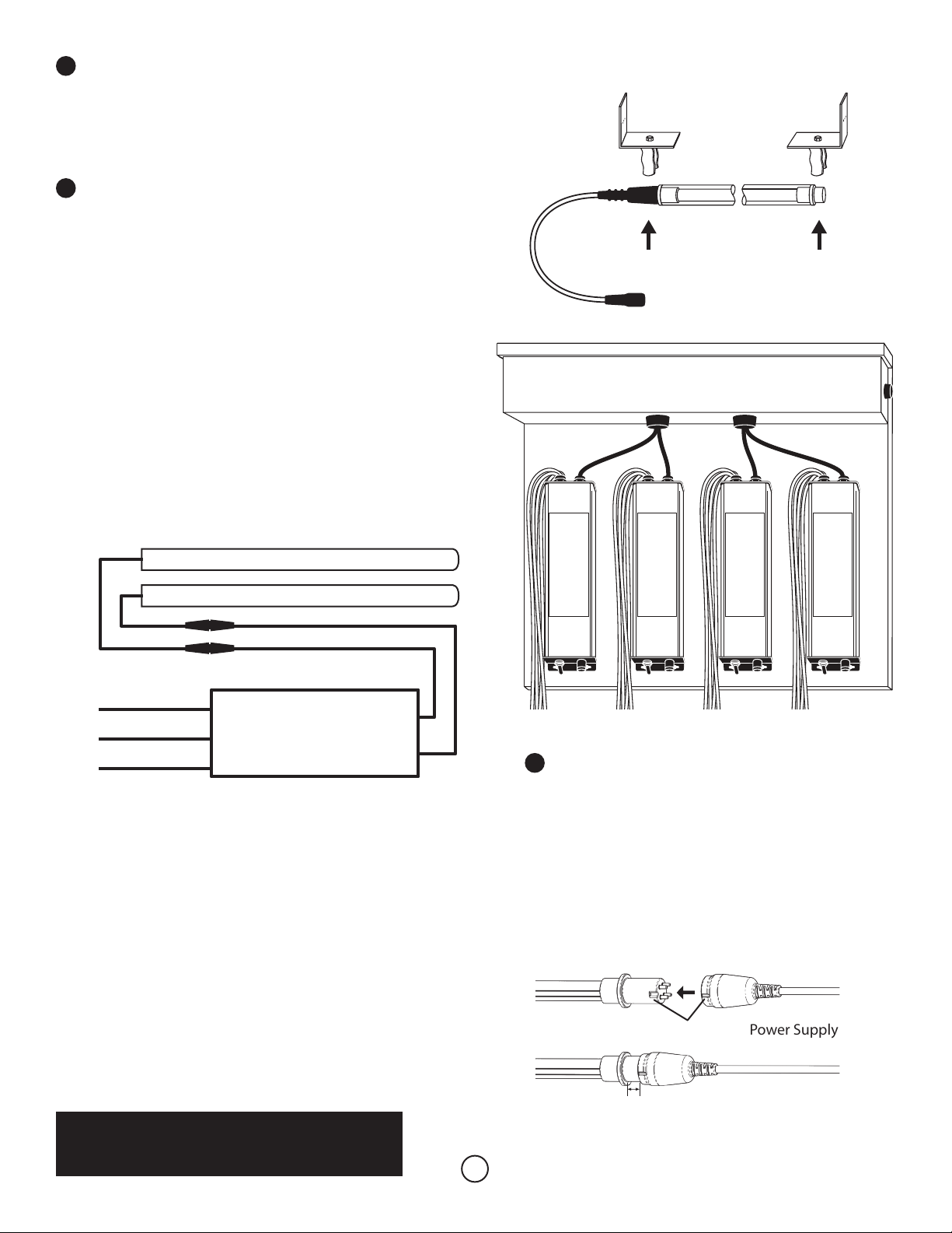
4Connect Lamps & Cables
Arrange cables as needed for installation. If necessary
use the Optional 3/4” or 1” Cable Strain Relief to pass
cables through cabinets, air system walls, etc. Optional
5’, 10’, 20’ Cable Extensions are available for longer runs.
When adding lamp extensions, 20 ft. is the maximum
distance from power supply to the lamp.
Align pins with lamp key then push rmly together.
Push Firmly Together
IMPORTANT!
Make sure connection is rmly seated with maximum
0.6” (15mm) gap between cable and ridge.
Power Supply Cable
0.6”
(15mm)
Lamp Key
WARNING
THIS SYSTEM TREATS EXHAUST AIR ONLY
DO NOT USE IN OCCUPIED SPACES
UV Lamp
2Install UV Lamps
Snap UV Lamps into the Lamp/conduit Clamps. Be sure to
clamp to the rubber lamp connector on one end and the plastic
lamp tip on the other end. DO NOT clamp onto the lamp glass.
3Mount Power Supply(s)
Mount the power supply in a location (inside or outside of the HVAC
system) that is convenient for access to the main power supply and
for connection to the UV lamps. An Optional Power Supply Panel
Mount (part # TUVC-P) is available for mounting two or more power
supplies.
1. Use the supplied self-taping sheet metal screws to mount the
power supply in place through the mounting holes on the sides
of the base. It is recommended to use wire boxes, our Optional
3/4” or 1” Cable Strain Relief, or other sealing methods in order
to pass the power cord and lamp cables into the interior of the air
duct for connections.
2. IMPORTANT! Turn o main power before making connections.
Refer to the Electrical Diagram for proper connection of the
power supply to the main power.
Electrical Diagram
UV LAMP
UV LAMP
120-277VAC
POWER SUPPLY
L1 BLACK
CONNECTORS
L2 or N WHITE
GND GREEN
IMPORTANT! Connect in accordance with all state and local
electrical and building codes. Proper voltage is automatically
selected by the unit between120-277VAC Single Phase 50/60 hz.
IMPORTANT! External power suppressor may be needed if
power surges occur.
3. Use of Optional Door Interlock Switches is highly recommended
to prevent accidental exposure to UV Light. Interlock switches are
mounted on the access panels and doors so the UV lights turn o
when the entryway is opened.
4. Use the Optional UV Output Monitor, to alert maintenance
personnel when UV lamps should be replaced.
Optional Power Supply Panel Mount
3