2
KWH150-ECO-LC/20210130Kair Ventilation Ltd | 9-11 High Street | Sidcup | DA14 6EN | www.Kair.co.uk
KWH150-ECO-LCInstallation Manual
2.0 INTRODUCTION
The KWH150-ECO-LC provides whole home ventilation using the
Positive Input Ventilation principle. The concept is to introduce
fresh, filtered air into the dwelling at a continuous rate, encouraging
movement of air from inside to outside.
To achieve this the unit is mounted in the loft space, drawing air
through the filters and inputting it, at ceiling level, into the property.
The KWH150-ECO-LC fan unit includes an internal sensor to regulate
the fan speed according to the temperature of the loft. The internal
sensor is to increase airflow to the dwelling when the loft is warmer
than the house. The units ‘Fixed Temperature Heat Recovery’ strategy
shall be achieved via a sensor located in the unit and shall improve
energy performance accordingly.
Once installed, the airflow can be set to suit the house size and, if
required, the way it responds to the temperature changes within.
3.0 MECHANICAL INSTALLATION
Whilst the installation of the KWH150-ECO-LC unit may be achieved
by suitable persons, the provision of the electrical supply and the
connection of the unit to the mains must be carried out by a qualified
electrician.
Successful operation of the fan depends entirely upon the unit being
installed strictly in accordance with these instructions.
Please read through this guide in its entirety before commencing
installation and follow step by step to ensure a satisfactory completion.
Warning: Isolate from power supply before removing any covers.
During installation/maintenance ensure all covers are fitted before
switching on the mains supply.
This appliance can be used by children aged from 8 years and above
and persons with reduced physical, sensory or mental capabilities or
lack of experience and knowledge if they have been given supervision
or instruction concerning use of the appliance in a safe way and
understand the hazards involved. Children shall not play with the
appliance. Cleaning and user maintenance shall not be made by
children without supervision.
Precautions must be taken to avoid the back-flow of gases into the
room from the open flue of gas or other fuel-burning appliances.
Means for disconnection must be incorporated in the fixed wiring as
shown in the wiring diagram in accordance with IEE wiring or national
wiring rules.
CAUTION: In order to avoid a hazard due to inadvertent resetting
of the thermal cut-out, this appliance must not be supplied
through an external switching device, such as a timer, or connected
to a circuit that is regularly switched on and off by the device.
3.1 Loft Inspection
Check to ensure that the loft has adequate ventilation. There may be
occasions where a loft is so well sealed that additional ventilation may
have to be provided by the owner/occupier.
Ensure that all water tanks are covered and sealed.
Check that all water pipes are lagged.
Ensure that any extract fans are discharging to outside and not into the
loft.
Check that the loft hatch is tightly sealed.
Ensure that all holes in the ceilings are sealed i.e. ceiling light fittings
etc.
Installer to visually inspect any flues or chimneys for leakage in the
loft. If any leakage points are found, or if there is any doubt at all,
then the installer should advise the house owner/provider as soon as
possible and seek instruction from them before proceeding with the
installation.
3.2 Diffuser Installation
3.2.1 Choosing Diffuser Location
The diffuser has a unique air throw pattern and it is essential that it is
located correctly in the central hallway in single storey properties or in
the ceiling of the top floor landing on 2 or more storey dwellings.
The diffuser discharges air evenly in all directions along the underside of
the ceiling.
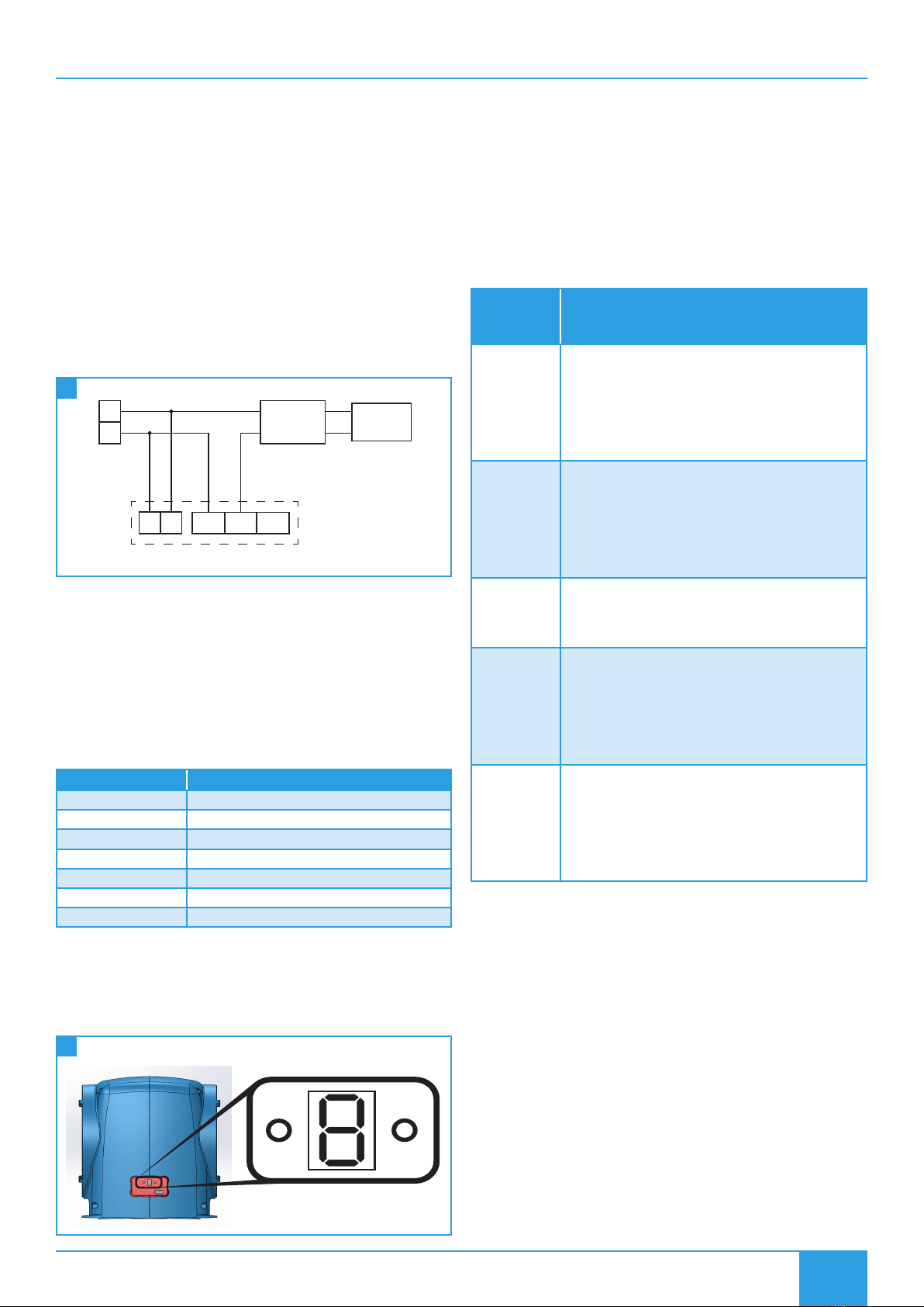
Speed Setting Minimum Diffuser Distance From Wall
1 100 mm
2 155 mm
3 400 mm
4 625 mm
5 850 mm
6 1000 mm
SMOKE ALARMS -It is also important to ensure that the diffuser is
NOT placed within 1 metre of a smoke alarm.
If the diffuser cannot be repositioned, two sides of the diffuser must
be closed off using the air dams supplied to encourage the air through
the remaining open sides that faces at least 1.5 metres of unobstructed
area away from the smoke alarm sensor.
3.2.2 Air Dam(s) Installation (If Required)
Air dams should be fitted as needed, to alter the direction of airflow
required. 2 air dams are supplied and will fit on any of the diffuser sides
to guide airflow away from a smoke detector and/or obstructions as
required.
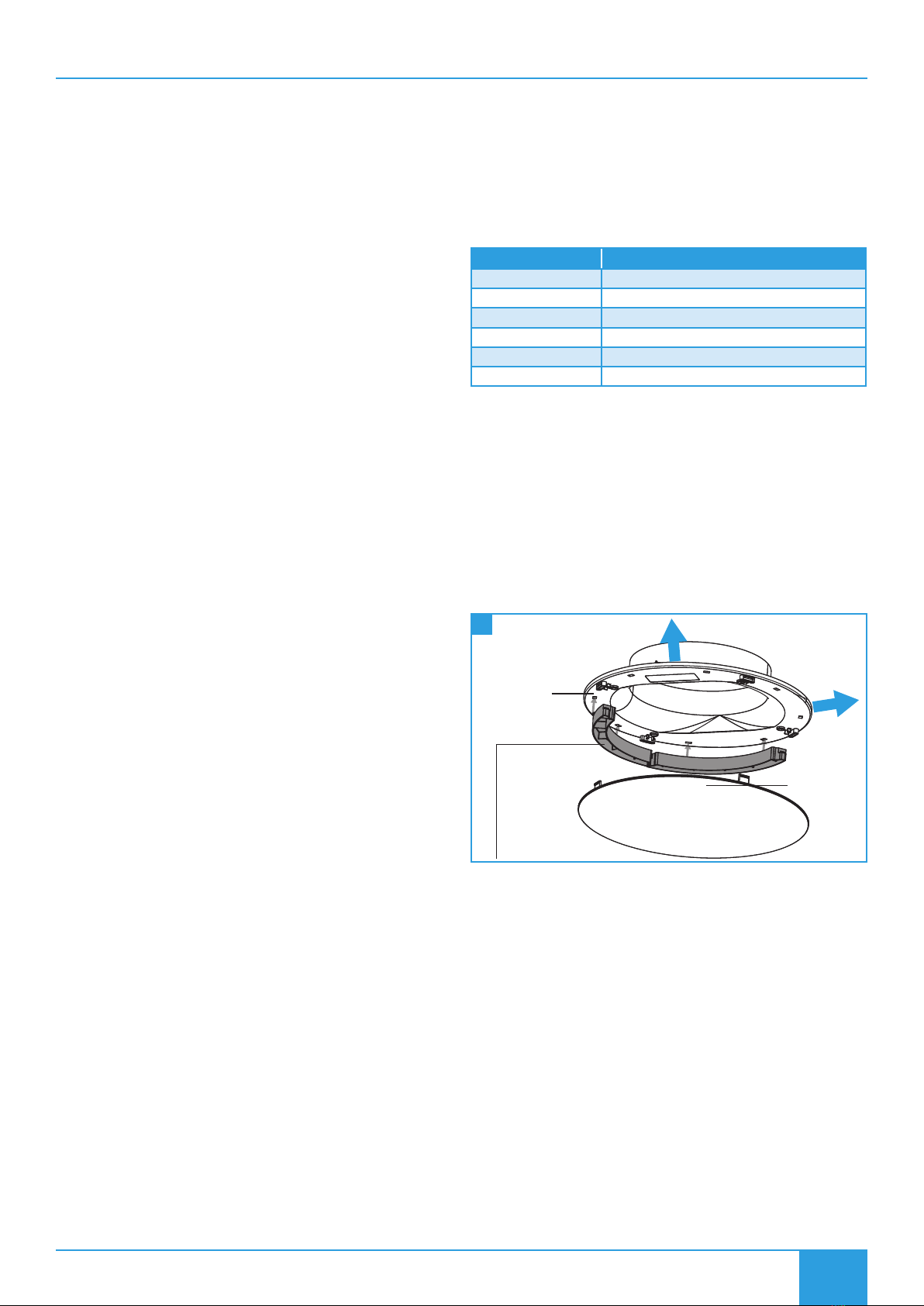
Ceiling Vent
Two Air Dams (supplied) can t on any of the diuser sides to guide
airow away from a smoke detector and/or obstructions as required.
Diuser Cap
Airow
Airow
1 Ceiling Diffuser With Air Dams
3.2.3 Ceiling Diffuser Installation
To install the diffuser, use the tear-out template from the lid of the unit
packaging and trace the shape onto the ceiling between two convenient
joists. Once the shape has been cut out, position the ceiling vent by
aligning the label on the ceiling vent with the narrowest point of the
ellipse and secure it in place using the 4 screws and plugs provided.
Finally attach the diffuser cap to the frame using the four built-in press
on clips provided.
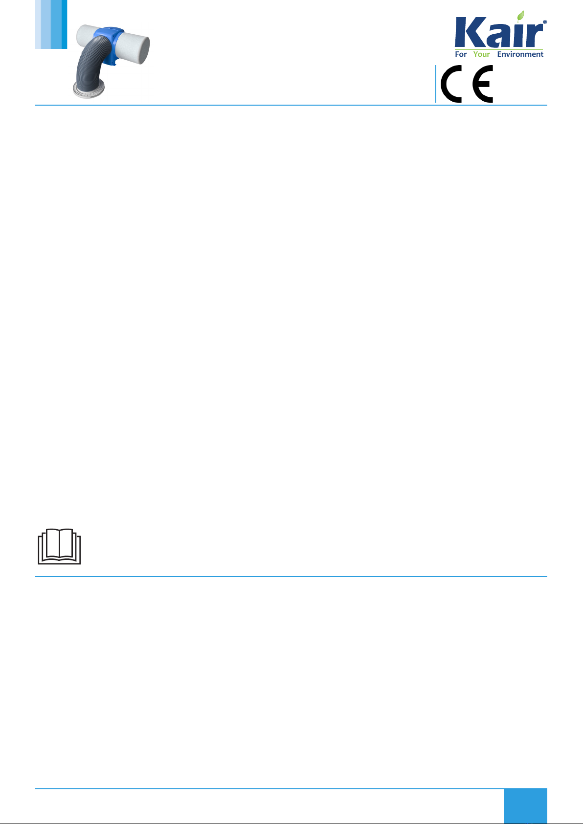
3.3 Filter Installation
The filter has a push fit rim to attach itself to the main body of the unit.
Offer the filters up to the unit and apply a small amount of pressure to
the filters rim (by hand). The filter will clip into place.
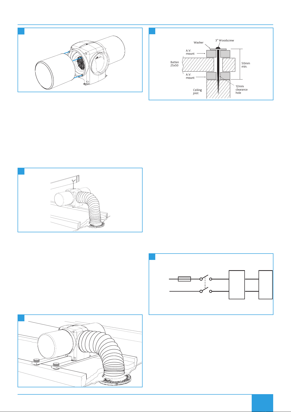
The unit can then be attached to the roof via the cord provided (or fixed
to the floor joists using the optional anti vibration mounting kit).