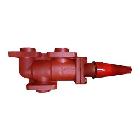
tozen PRV-CPR User manual

20201203
PRV-CPR
Pressure Reducing valve
Instruction Manual

Thank you very much for purchased Tozen products.
Please read the Instruction Manual before use to ensure using this product in correctly and safely
way.
The definition of the symbol use in the text as below shown: -
・△
! Warning : If did not implement protection measure, may result in death or
seriously injury.
・△
! Caution : If did not implement protection measure, may cause minor injury or
parts damaged.
Contents
1.Application
2.Specification
3.Operation
4.Installation
4.1 Installation Example
4.2 Precaution
4.3 Installation Space
5.Operation Manual
5.1 Precaution
5.2 Procedure
6.Maintenance Manual
7.Cause & Counter Measure Of Malfunction
8.Sizes Selection Diagram Sizes Selection Diagram & Pressure Reducing Valve (When Pilot
Valve Fully Open) Flow Chart
1.Application
Building equipment, air-conditioning equipment, factory equipment, irrigation facility, the
water supply piping to reduce pressure on outlet or downstream side and maintain a certain
range.
2.Specification
Model PRV-CPR
Sizes (mm) 65~150
Application Fluid Water, Warm Water
Fluid Temperature 5~60℃
Applicable Inlet Pressure Under 1.6MPa
Max. Pressure Reduction Ratio 10:1
Connection BS4504-3.2 PN16RF Flange (GB/T9113.1, EN1092-1)
Material
Body FCD450
Main Part Seat : SCS13A, Diaphragm, Shield Ring : NBR

3.Operation
(Pressure Reducing Valve Body)
(Pilot Valve)
Adjustment bolt
Cap
Nut
(Needle Valve)
Cap
Nut
Stem Diaphragm
Diaphragm
Disc Assembly
1.The PRV body 's disc assembly will rises and the PRV valve opened from inlet pressure.
Or haven't adjusting the pilot valve, the needle valve under opened condition and no heavy
load on adjusting bolt, the fluid will let through pilot tube to pilot valve from upper part of
the diaphragm in the PRV body.
2.The lower part of the diaphragm in the pilot valve pressure increase, the disc assembly of the
pilot valve will rise, and the pilot valve will closed.
3.The pilot valve closed, the upper part of the diaphragm in the PRV body pressure will increase,
the PRV disc assembly will drop down, and the PRV closed.
4.To setting outlet pressure of the PRV, removed the cap which on top of the pilot valve,
clockwise turn the adjustment bolt, the outlet side pressure will increase, turn anti clockwise
will reduce the pressure.
△
! Caution
⦿ To use this product, please make sure can meet the application condition.
⦿ Please do daily checking and periodic inspection to maintain this product's function and
performance.

4.Installation
4.1 Installation Example
4.2 Precaution
△
! 注意
△
! Warning
⦿ Please pay necessary attention make sure have proper support when install this
product to the pipe system, as this product is heavy.
※In case of this product drop down, there is a risk to get hurt.
⦿ After installation, before water flow, make sure all the pipe work been proper installed.
※If the water spouting off the pipe line, it may dirty the surrounding and there is a
risk to get hurt.
△
! Caution
⦿ Remove the foreign matters in the pipe line before install the valve.
※The valve can't have the original performance and may damage if foreign particle
in the valve.
⦿ Propose to install strainer (40 mesh or above) on inlet side.
※The valve can't have the original performance and may damage if foreign particle
in the valve.
⦿ Must install stop valve on both inlet & outlet side.
※Unable to do maintenance if do not have stop valve.
PN16
DN80
3
Pressure Reducing Valve(TRV-P)
Strainer
Shut Off Valve
Bypass pipe
Discharge
pipe
Shut Off Valve
Shut Off Valve

4.3 Installation Space
PN16
DN80
3
H
W
⦿ It is recommended to install by-pass line.
※When doing maintenance, the water flow may stop if do not have by-pass line.
⦿ Make sure the valve's flow arrow direction follow the pipe flow direction when install
the valve.
※There are no function if installed wrong direction.
⦿ Please proper support the pipe line to avoid the valve facing the pipe weight, unreasonable
force, bending, vibration.
※If do not support the pipe line properly, the valve may damage or the reason of operation
failure.
⦿ To avoid pipe freezing, drain the pipe water and thermal insulation the pipe.
※By freezing, may damage the valve.
⦿ Please secure the installation space. (refer to 4.3 Installation Space)
※When doing maintenance and inspection, unable to dismantle and assembly the
valve if do not have enough space.
⦿ The valve can be installed to horizontal and vertical pipe line. For vertical pipe line, when doing
maintenance and inspection, may have difficulty to dismantle and assembly the valve. It is
recommended to install on horizontal pipe.
※For vertical pipe line, especially when dismantle the heavy and big sizes valve,
may accidentally damage the parts.
Unit:mm
Size H W
65A 600 600
80A 600 600
100A 800 700
125A 1000 800
150A 1200 900

5.Operation Manual
5.1 Precautions
5.2 Procedure
①Please close the shut off valve at inlet side, outlet side and by-pass line.
②Open the valve from supply source, then slowly open the by-pass line's shut off valve, let
the water flow cleaning the pipe.
③Close the by-pass line's shut off valve.
④At inlet side, turn the shut off valve to around half open, then slowly turn the shut off valve
to around 1/4 open at outlet side, let the water flow awhile. This is to let the air out of the
pipe, the product internal air can get out, at outlet side the valve should start function to
reduce the pressure.
When occurred hunting or no pressure reduce function, turn the bonnet plug open, let the
air out of the valve body.
△
! Warning
⦿ After installation, before water flow, make sure all the pipe work been proper installed.
※If the water spouting off the pipe line, it may dirty the surrounding and there is a
risk to get hurt.
△
! Caution
⦿ Remove the foreign particles in the pipe line before install the valve.
※The valve can't have the original performance and may damage if foreign particles
in the valve.
⦿ When water flow, to avoid happened water hammering, please slowly open the stop valve.
※If rapidly open the stop valve, hunting and water hammering may occurred, also
may damage the valve.
⦿ If the pipe line long period not running, closed the stop valve, drain dry the valve and pipe line.
※The water dirt in the pipe line may cause operation failure.
⦿ If open the shut off valve of the by-pass line, make sure the outlet pressure not over the outlet
setting pressure by confirmation with pressure gauge and slowly adjust the valve.
△
! Caution
⦿ Please do not open the shut off valve at outlet side bigger than inlet side.
※Hunting and water hammering may occurred.

⑤If no happened abnormal, fully open the inlet side shut off valve, then fully open outlet
side shut off valve.
⑥To setting outlet side pressure, open the upper cap of the pilot valve, checking the pressure
gauge at outlet side, to let the setting pressure higher, turn the adjusting bolt clockwise,
to lower the setting pressure, turn to anti clockwise.
6.Maintenance Procedures
7.3 分解図
△
! Warning
⦿ If want to dismantle the valve, close the Inlet side shut off valve, drain the water out
from the valve body, outlet side pressure become zero, only can proceed.
※If the water spouting off the pipe line, it may dirty the surrounding and there is a
risk to get hurt.
△
! Caution
⦿ To maintain this product's function & performance, please perform daily checking and
regular inspection.
⦿ To dismantle the valve, please perform by the skilled specialist (facility contractor).
※If done by normal people, the valve may lost the adjusting function.
△
! Caution
⦿ Other than main body have strainer, this product's needle valve at inlet side in the pilot tube
also have strainer, if foreign matter stick to the strainer, please remove it.
※If the strainer clogging, the valve may not function.

7.Cause & Counter Measure Of Malfunction
Condition Possible Cause Countermeasure
Outlet side
pressure increase
The valve body have plenty of air Please relief the air out of the
valve body.
Refer to 5. Operation Manual.
Foreign Particles stuck in the valve
(Stick at seat ring, shield ring, Pilot valve's
seat ring and shield ring)
Remove the foreign particles.
Part's Damage
(Seat ring, shield ring, Pilot valve's seat ring
and shield ring)
Exchange the main body shield
ring, and pilot valve shield ring.
PRV main body seat ring, pilot
valve body seat ring part if
serious damage, please exchange
the part.
The valve body's stem can't operate
smoothly.
(Stem, seat, guide bush)
Use cloth file to filing the stem,
make it smooth to operate.
Pilot valve's diaphragm damaged. Exchange the part
Strainer clogging Clean the strainer mesh
Outlet side
pressure does not
rise
The valve body's stem can't operate
smoothly.
(Stem, seat, guide bush)
Use cloth file to filing the stem,
make it smooth to operate.
Wrong selection of the sizes
(Nominal diameter too small)
Reconfirm the specification and
change the nominal diameter
sizes.
Piping resistance too big Checking the piping
Operation Failure
(Pulsation,
vibration,
pressure
unstable)
Air pocket in the piping Proceed to relief the air, or install
the air vent
Wrong selection of the sizes Reconfirm the specification and
change the nominal diameter
sizes.
Pressure reduction ratio too big Do two steps pressure reducing
Poor adjustment of the needle valve Small opening of the needle
valve, the disc assembly of the
PRV body easy to operate and
also insensitivity easily.
If opening too big, the disc
assembly of the valve body,
operation easily become
unstable and acutely.

8.Sizes Selection Diagram Sizes Selection Diagram & Pressure Reducing Valve (When Pilot
Valve Fully Open) Flow Chart
(Note) Max.3m/s flow speed.
Sizes selection diagram TRV-P (Pilot Valve fully
Open) Performance-Flow Chart
Flow rate
Differential
p
ressur
e
Flow velocit
y
Other tozen Control Unit manuals
Popular Control Unit manuals by other brands

LOVATO ELECTRIC
LOVATO ELECTRIC EXM10 10 instruction manual
Zehnder Rittling
Zehnder Rittling ComfoSense Series manual

Growatt
Growatt ShineWiFi-X2 Configuration guide
Reporter
Reporter Oracle 3000 manual

SMART Embedded Computing
SMART Embedded Computing Penguin Edge RTM-ATCA-F140 manual
CALEFFI
CALEFFI 455 Series manual
Seifert
Seifert 42710001 user manual
National Instruments
National Instruments SCXI-1520 CALIBRATION PROCEDURE
Matheson
Matheson 6295 Series operating instructions

Bartec
Bartec VOLUTANK Petro 3003 operating instructions
Watson McDaniel
Watson McDaniel WD600S Installation and maintenance manual

IDS
IDS AM-1024768Z3TZQW-TH0H quick start guide
