TPC L600-LED User manual

L600-LED Operatory Light
Installation and Operation Manual
TPC
851 S. Lawson St
City Of Industry, CA 91748
P. 626-810-4337 Fax 626-810-4245

Table on Contents:
General information
Installation
Overview of components
Operation instructions
Light head and vertical arm adjustment
Replacement Parts List
Cleaning & disinfection guide
Warranty
Troubleshooting Guide
Technical Assistance is available Monday through
Friday, 8:00 AM to 5:00 PM PST.
800 560 82222

SYMBOLS
DANGER
The paragraphs marked with this symbol contain instructions
which must be followed carefully to avoid damaging the device,
the operator and the patient.
WARNINGS
These instructions warn the operator that it is mandatory to operate
with utmost care to avoid situations which could damage the device.
RESTRICTION
This icon indicatesthe most appropriatebehavior to avoid damaging the
device.
RECOMMENDATIONS
This icon indicates useful details for an effective use of the device.
Dispose of the device according to the regulations on separate waste
collection of electrical equipment. Directive WEEE 2012/19/EC
Class II device.
Refer to the documentation enclosed..
!
SERIAL NUMBER
ITEM CODE
STERILISATION
RELA TIVE HUMIDITY
ATMOSPHERIC PRESSURE
TEMPERATURE
Danger warning symbol
SWITCH SYMBOLS
SENSOR
OFF
ON
ADJUSTMENT
Specications
Input Voltage : AC 24V Frequency: 50/60Hz
Power : 28W Illumination: 8000-23000 Lux
Color Temperature: 4000-5000 K can be adjustable
Spot Size: 80 * 160 mm (Distance for 700mm)
Package Contents
1. Light Arm
2. Power Supply
3. Light head (Seperate Box)
4. Lght head handles (Included In Light Head Box)
5. Manual
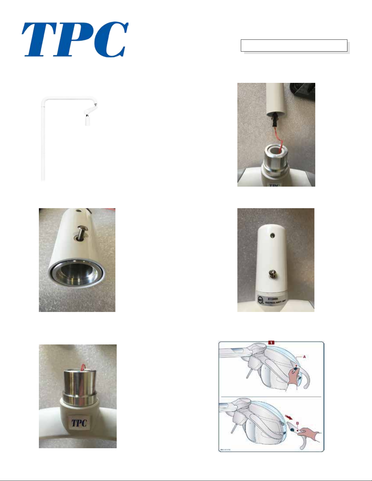
Installation Instructions
1. Install Light arm to light post. 1 11/16” Nylon
light post bushing is required for a proper t.
4. Connect power from light arm to light head
harness.
2. Remove adaptor bushing from light arm.
3. Attach adaptor bushing to light head.
5. Secure light head to arm using the alllen screw
removed in step 2.
6. Attach light handles to the light head.

Overview of Controls
On/O switch: Toggle in either
direction “Le” or “Right”
to turn the light to the “ON”
position.
Press and hold in either direc-
tion to increase or decrease the
intensity of the light.
Note: when the light is pow-
ered “o” the light inensity
remains at the last setting.
Touch Sense: Gently place your
palm on the back of the light
towards the bottom of the back
cover. is will turn the light
on and o.
Leave hand on touch sense pad
and the intensity of the light
will adjust. When you remove
your palm from the back the
intensity adjustment will stop.
Note: when the light is pow-
ered “o” the light inensity
remains at the last setting.

FEATURES
Versions
• “EDI LED” head can be supplied in the following versions:
• Head with switch
• Head with switch + automatic lighting function
• Head with con proximity sensor
• Head with switch + automatic lighting function
• Light source consisting of two LEDs whose light is mirrored into two parabolic reectors.
• Reecting surfaces with parabolic reectors which allow obtaining a regular uniform spot light at all lighting
levels and to uniformly distribute the light in the operating eld with no shadows or dark areas created by the
operator.
• Light intensity adjustment using a mechanical switch or with a sensor.
• Sensor enables the light to be switched on or o without direct contact, eliminating therefore the possibility
of cross-infection.
• “Automatic lighting” function allows the lamp to get switched on automatically whenever the power is en-
abled.
• Easy maintenance thanks to the application of new technology that takes into consideration various require-
ment in terms of safety, ergonomics and hygiene.
• Removable handles for sterilization
• Front screen lower signicantly internal contamination of the device.
• Electrical connection - Follow the wiring diagrams

Vertical Arm Adjustment
If you experience a downward dri with your operatory lights’ verti-
cal arm please follow the procedure below.
• Remove the end cap cover on the end of the vertical arm closest to
the light head. is requires a small Phillips screw driver.
• Turn the nut located at the end of the light arm to adjust the ten-
sion.
• Turn the nut clockwise to increase the tension. Turn the nut
counter clockwise to decrease the tension.
• If your vertical light arm dris down then you need to increase the
tension.
• If the vertical light arm dris back up you need to adjust the fric
tion screw. Only adjust the friction screw in quarter turns.
Tension Nut Friction Screw


Cleaning and Disinfecting Guide
*e Manufacturer makes no representation as to the disinfectant ecacy of these products. We make no war-
ranty expressed or implied that these disinfectants will not damage the surface nishes. Damage and discolor-
ation of the surface nishes are not covered under the warranty. Iodophor based disinfectants will cause yellow
staining on many surfaces. Regular washing with soap and water will minimize this staining. Iodophor neutraliz-
ers such as Promedyne are also available.
Unacceptable Disinfectants
ese disinfectants will harm the surface
nishes of dental equipment and are not
recommended.
Use of these products will void your
warranty.
Chemical Composition / Trade Names
Strong Phenols / Lysol, Lysol 2, Lysol
Phenol Alcohol Professional, Coe Foam, Coe
combinations Spray Pump, Vitaphene, Omni II
Sodium Hypochlorite / Clorox, Ajax, Purex
Household Bleach
Alcohol
Household Cleaners
Conditionally Acceptable Disinfectants
ese disinfectants have been found to be the
least
harmful to the equipment surfaces by our test
methods.
Chemical Composition Trade Names
Iodophors Biocide, Aseptic IDC,
Wescodyne, SD5, Promedyne,
Iodo Five
Mild Phenols Procide ES, Asepti Steryl
Aerosol
Glutaraldehyde / Sterall Spray, Coldspor
Phenol Sprays
Synergized Super Dis cide, Cavicide,
Kleenaseptic
Quat
Phenol/Water Sprays Top Cide, Sporicidin Pump
Spray
Birex se

Warranty Information
LED Operatory lights are guaranteed to be free from defects in workman-
ship and materials for a 2 years from date of purchase, unless otherwise
stated. TPC will repair or replace any defective “part” at no charge. TPC
will not be responsible for labor charges or shipping charges to / from the
TPC facility. is guarantee does not cover normal wear or stains on sur-
face nish. e guarantee does not cover damage resulting from improper
installation, misuse or accidents incurred in shipping and handling. All
claims against the freight carrier must be initiated at the time the damaged
items are received. e claim is the responsibility of the customer. We are
improving our products on a continuous basis. We reserve the right
to make modications without the need for prior notication and are not
obliged to modify previously manufactured items. Light bulbs are not
covered under any type of warranty. Only authorized service technicians
should attempt to service TPC equipment. Service performed by any unau-
thorized technician may result in a voided warranty.
Problem Cause Solution
Light does not illuminate No power to light Check power
LED has expired Replace LED
Transformer is expired Replace transformer
Light turns on and o then
the light head is moved
Open in line power check light head to ridge arm con-
nector. Inspect arm wire.
Vertical arm dris down Tension needs to be increased in
arm
tighten arm tension adjustment
Verticle arm dris up Friction arm adjustmnet loose Tighten friction arm adjustment
Light dris from le to right Light post not level Level unit / light post
Troubleshooting guide
Table of contents
Popular Lighting Equipment manuals by other brands


MEDC
MEDC FL12 Technical manual

HanleyLED
HanleyLED PHOENIXNRG STREAMLINER quick start guide

GRILL MEISTER
GRILL MEISTER 967-UL manual

Rollei
Rollei Candela 220 Bi-Color manual

Clevertronics
Clevertronics CleverEVAC LP Cleverfit Pro DYRC CP Series Installation & maintenance instructions

Future light
Future light MH-420 Spotlight user manual